


Operation & Safety
An Oshkosh Corporation Company
Manual
Original Instructions
Keep this manual with machine at all times.
Models
3508PS, 3509PS,
3512PS, 3513PS,
4008PS, 4009PS,
4012PS, 4013PS,
4017PS
31200205
Revised
August 28, 2012


Revision Log
Revision Log
REVISION LOG
August 10, 2007 - A - Original Issue of Manual
December 12, 2007 - B - Added platform information. Revised pages c, 2-5, 3-2,
3-3, 3-5, 3-8, 3-9, 3-14, 3-16, 3-22, 4-1, 4-3, 5-10, 5-11, 5-30, 6-2, 6-3, 7-18, 7-19,
8-5, 9-1 & 9-4.
March 5, 2008 - C - Revised pages 2-5 & 9-7.
May 16, 2008 - D - Revised pages c, d, 1-4, 1-9, 2-3, 3-2, 3-3, 3-7, 4-4 thru 4-9, 5-4,
5-6, 5-15 & 9-3.
November 16, 2009 - E - Revised covers and page 9-7.
February 26, 2010 - F - Revised pages d, 1-2 thru 1-6, 1-9, 2-1, 2-4 thru 2-9, 3-2 thru
3-8, 3-11, 3-12, 3-14 thru 3-27, 3-29, 4-1 thru 4-12, 5-1 thru 5-46, 6-1, 6-3, 7-1 thru
7-4, 7-10, 7-11, 7-12, 7-14 thru 7-17, 7-19 thru 7-22, 8-2, 8-3 & 9-2 thru 9-5.
August 30, 2010 - G - Revised pages 2-6, 2-7, 3-14, 3-15, 7-4 & 8-1.
November 11, 2010 - H - Revised pages 2-5, 3-14, 3-15 & 3-16.
December 23, 2010 - I - Revised pages 5-2 & 5-3.
August 28, 2012 - J - Revised pages 5-2 & 5-3.
a31200205

Read This First
Read This First
This manual is a very important tool! Keep it with the machine at all times.
The purpose of this manual is to provide owners, users, operators, lessors, and
lessees with the precautions and operating procedures essential for the safe and
proper machine operation for its intended purpose.
Due to continuous product improvements, JLG Industries, Inc. reserves the right to
make specification changes without prior notification. Contact JLG Industries, Inc.
for updated information.
Operator Qualifications
The operator of the machine must not operate the machine until this manual has
been read, training is accomplished and operation of the machine has been
completed under the supervision of an experienced and qualified operator.
Operation within the U.S.A. requires training per OSHA 1910.178.
Operators of this equipment must possess a valid, applicable driver’s license, be in
good physical and mental condition, have normal reflexes and reaction time, good
vision and depth perception and normal hearing. Operator must not be using
medication which could impair abilities nor be under the influence of alcohol or any
other intoxicant during the work shift.
In addition, the operator must read, understand and comply with instructions
contained in the following material furnished with the material handler:
• This Operation & Safety Manual
• Telehandler Safety Manual (ANSI only)
• All instructional decals and plates
• Any optional equipment instructions furnished
The operator must also read, understand and comply with all applicable Employer,
Industry and Governmental rules, standards and regulations.
Modifications
Any modification to this machine must be approved by JLG.
b 31200205

Read This First
This product must comply with all safety related bulletins. Contact JLG Industries,
Inc. or the local authorized JLG representative for information regarding safetyrelated bulletins which may have been issued for this product.
JLG Industries, Inc. sends safety related bulletins to the owner of record of this
machine. Contact JLG Industries, Inc. to ensure that the current owner records are
updated and accurate.
JLG Industries, Inc. must be notified immediately in all instances where JLG
products have been involved in an accident involving bodily injury or death of
personnel or when damage has occurred to personal property or the JLG product.
FOR:
• Accident Reporting and Product Safety Publications
• Current Owner Updates
• Questions Regarding Product Applications and Safety
• Standards and Regulations Compliance Information
• Questions Regarding Product Modifications
CONTACT:
Product Safety and Reliability Department
JLG Industries, Inc.
13224 Fountainhead Plaza
Hagerstown, MD 21742
USA
or Your Local JLG Office
(Addresses on back cover)
In USA:
Toll Free: 1-877-JLG-SAFE (1-877-554-7233)
Outside USA:
Phone: +1-717-485-6591
E-mail:
ProductSafety@JLG.com
c31200205

Read This First
Other Publications Available
Service Manual............................................................................................31200206
Illustrated Parts Manual...............................................................................31200204
Load Management Indicator System Operation & Safety
Manual (if equipped)................................................................................Contact JLG
Platform for 3513PS, 4013PS & 4017PS Operation &
Safety Manual (if equipped for platform) .................................................Contact JLG
Note: The following standards may be referenced in this manual:
ANSI is compliant to ANSI/ITSDF B56.6
AUS is compliant to AS 1418.19
CE is compliant to EN1459
Refer to the machine Serial Number Plate to identify the applicable compliance
standard.
d 31200205

Table of Contents
TABLE OF CONTENTS
Revision Log
Read This First
Operator Qualifications ...................................................... b
Modifications ...................................................................... b
Other Publications Available .............................................. d
Table of Contents
Section 1 - General Safety Practices
1.1 Hazard Classification System ..............................................1-1
Safety Alert System and Safety Signal Words................1-1
1.2 General Precautions ............................................................1-1
1.3 Operation Safety ..................................................................1-2
Electrical Hazards ...........................................................1-2
Tip Over Hazard..............................................................1-3
Travel Hazard ................................................................. 1-6
Load Falling Hazard ........................................................1-7
Lifting Personnel .............................................................1-8
Driving Hazards on Slopes .............................................1-9
Pinch Points and Crush Hazards ..................................1-10
Fall Hazard....................................................................1-12
Chemical Hazards.........................................................1-13
Table of Contents
Section 2 - Pre-Operation and Inspection
2.1 Pre-Operation Check and Inspection...................................2-1
2.2 Safety Decals.......................................................................2-3
2.3 Walk-Around Inspection.......................................................2-6
2.4 Warm-Up and Operational Checks ......................................2-8
Warm-Up Check ............................................................. 2-8
Operational Check .......................................................... 2-8
2.5 Operator Cab .......................................................................2-9
2.6 Windows ............................................................................2-10
Cab Door Window .........................................................2-10
Rear Window ................................................................2-10
Section 3 - Controls and Indicators
3.1 General ................................................................................ 3-1
3.2 Controls ...............................................................................3-2
Instrument Panel ............................................................. 3-4
Display Screen................................................................3-6
Keypad............................................................................3-8
Ignition ..........................................................................3-10
Park Brake ....................................................................3-11
i31200205

Table of Contents
Parking Procedure........................................................ 3-11
Transmission Control Lever.......................................... 3-12
Load Stability Indicator (LSI) ........................................ 3-14
Steering Column Adjuster............................................. 3-17
Joystick......................................................................... 3-18
Armrest and Right Hand Console................................. 3-22
Accessory Control Lever .............................................. 3-24
3.3 Anti Theft ........................................................................... 3-25
3.4 Steer Modes ...................................................................... 3-26
Manual Steering Alignment Mode Change................... 3-26
All Wheel Assisted Steering Alignment Mode
Change ......................................................................... 3-27
3.5 Operator Seat.................................................................... 3-28
Adjustments.................................................................. 3-28
Seat Belt ....................................................................... 3-30
3.6 Boom Indicators ................................................................ 3-31
Boom Extension ........................................................... 3-31
Boom Angle (AUS) ....................................................... 3-31
Section 4 - Operation
4.1 Engine ................................................................................. 4-1
Starting the Engine ......................................................... 4-1
Battery Boosted Starting................................................. 4-2
Normal Engine Operation ............................................... 4-3
Shut-Down Procedure .................................................... 4-3
4.2 Operating with a Non-Suspended Load .............................. 4-4
Lift Load Safely............................................................... 4-4
Picking Up a Load .......................................................... 4-4
Transporting a Load ....................................................... 4-5
Leveling Procedure......................................................... 4-5
Placing a Load................................................................ 4-6
Disengaging a Load........................................................ 4-6
4.3 Operating with a Suspended Load ...................................... 4-7
Lift Load Safely............................................................... 4-7
Picking Up a Suspended Load ....................................... 4-7
Transporting a Suspended Load .................................... 4-8
Leveling Procedure......................................................... 4-8
Placing a Suspended Load............................................. 4-9
Disengaging a Suspended Load .................................... 4-9
4.4 Road Operation (CE)......................................................... 4-10
4.5 Loading and Securing for Transport .................................. 4-11
Tiedown ........................................................................ 4-11
Lifting ............................................................................ 4-12
ii 31200205

Section 5 - Attachments and Hitches
5.1 Approved Attachments ........................................................ 5-1
5.2 Unapproved Attachments ....................................................5-1
5.3 JLG Supplied Attachments .................................................. 5-2
3508PS, 3509PS, 3512PS, 4008PS, 4009PS
& 4012PS........................................................................5-2
3513PS, 4013PS & 4017PS ...........................................5-3
5.4 Telehandler/Attachment/Fork Capacity................................ 5-4
5.5 Use of the Capacity Chart....................................................5-5
Capacity Indicator Locations ...........................................5-5
Sample Capacity Chart (CE)...........................................5-6
Sample Capacity Chart (AUS) ........................................ 5-8
Example ........................................................................5-10
5.6 Attachment Installation ......................................................5-11
JLG Quick Attach ..........................................................5-11
Manitou Quick Attach ....................................................5-16
Hydraulic Operated Attachment ....................................5-18
Platform Attachment (If Equipped) ................................5-18
5.7 Adjusting/Moving Forks......................................................5-19
5.8 Attachment Operation ........................................................ 5-20
Carriage w/Forks...........................................................5-21
Side Shift Carriage ........................................................5-22
Fork Positioning Carriage .............................................5-24
Fork Extension ..............................................................5-26
Fork Mounted Hook ......................................................5-28
Quick Attach Mounted Hook ......................................... 5-30
Truss Boom...................................................................5-31
Bucket ...........................................................................5-32
Multi-Purpose Bucket ....................................................5-34
Grapple Bucket .............................................................5-36
Concrete Bucket - Fork Mounted ..................................5-38
Platform.........................................................................5-40
5.9 Hitches (3508PS, 4008PS, 3509PS & 4009PS) ................5-41
Pin Hitch - CUNA C (Italy).............................................5-41
Pin Hitch - CUNA D2 (Italy)...........................................5-42
Pin Hitch........................................................................5-43
Auto Hitch .....................................................................5-44
Piton Frame and Auto Hitch ..........................................5-45
Hydraulic Hitch..............................................................5-46
Table of Contents
iii31200205

Table of Contents
Section 6 - Emergency Procedures
6.1 Towing a Disabled Product ................................................. 6-1
Moving Short Distances.................................................. 6-1
Moving Longer Distances ............................................... 6-1
6.2 Emergency Lowering of Boom ............................................ 6-2
6.3 Emergency Lowering of Boom If Equipped for Platform ..... 6-3
Auxiliary Power System.................................................. 6-3
6.4 Cab Emergency Exit............................................................ 6-4
Section 7 - Lubrication and Maintenance
7.1 Introduction.......................................................................... 7-1
Clothing and Safety Gear ............................................... 7-1
7.2 General Maintenance Instructions....................................... 7-2
7.3 Service and Maintenance Schedules .................................. 7-3
8 & 1st 50 Hour Maintenance Schedule ......................... 7-3
50, 250 & 500 Hour Maintenance Schedule................... 7-4
1000 & 1500 Hour Maintenance Schedule..................... 7-5
7.4 Lubrication Schedules ......................................................... 7-6
8 Hour Lubrication Schedule .......................................... 7-6
50 Hour Lubrication Schedule ........................................ 7-8
7.5 Operator Maintenance Instructions ................................... 7-10
Fuel System.................................................................. 7-10
Air Intake System ......................................................... 7-12
Engine Oil ..................................................................... 7-14
Hydraulic Oil ................................................................. 7-15
Tires.............................................................................. 7-16
Brake System ............................................................... 7-18
Transmission ................................................................ 7-19
Engine Cooling System ................................................ 7-20
Battery .......................................................................... 7-21
Windshield Washer System.......................................... 7-22
Section 8 - Additional Checks
8.1 General................................................................................ 8-1
8.2 Load Stability Indicator Test................................................ 8-1
8.3 Boom Interlock .................................................................... 8-2
8.4 Outrigger Interlock (4017PS Only) ...................................... 8-4
8.5 Auxiliary Power (If Equipped for Platform) .......................... 8-5
iv 31200205

Section 9 - Specifications
9.1 Product Specifications ......................................................... 9-1
Fluid and Lubrication Capacities .....................................9-1
Tires ................................................................................9-2
Performance ................................................................... 9-3
Dimensions .....................................................................9-6
Declaration of Vibration (CE) ..........................................9-8
Noise Emission Level (CE) ............................................. 9-8
Index
Inspection, Maintenance and Repair Log
Table of Contents
v31200205

Table of Contents
vi 31200205
Section 1 - General Safety Practices
DANGER
OW0010
WARNING
OW0021
CAUTION
OW0031
SECTION 1 - GENERAL SAFETY PRACTICES
1.1 HAZARD CLASSIFICATION SYSTEM
Safety Alert System and Safety Signal Words
DANGER indicates an imminently hazardous situation which, if not avoided, will
result in death or serious injury.
WARNING indicates a potentially hazardous situation which, if not avoided, could
result in death or serious injury.
CAUTION indicates a potentiality hazardous situation which, if not avoided, may
result in minor or moderate injury.
1.2 GENERAL PRECAUTIONS
WARNING
Before operation, read and understand this manual. Failure to comply with the
safety precautions listed in this manual could result in machine damage, property
damage, personal injury or death.
1-131200205
Section 1 - General Safety Practices
OW0040
10 FT
(3 M)
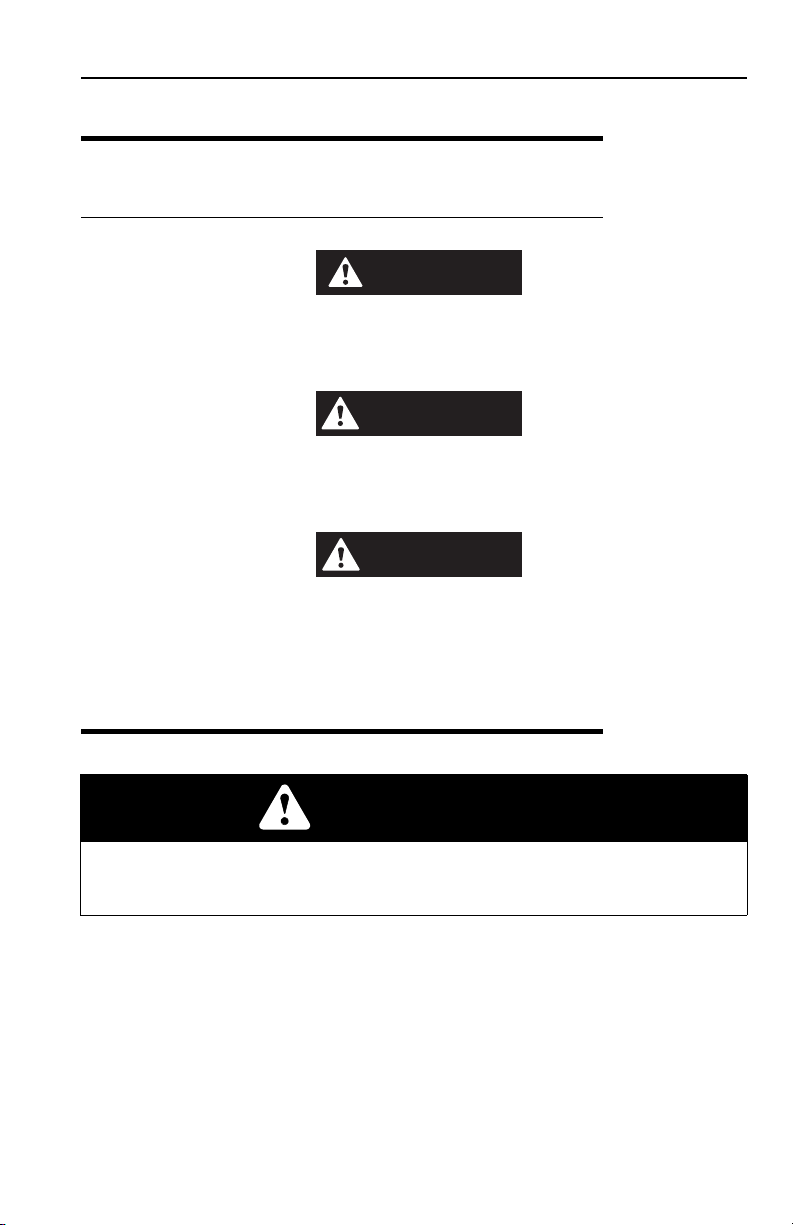
1.3 OPERATION SAFETY
Electrical Hazards
• This machine is not insulated and does not provide protection from contact or
being near electrical current.
• NEVER operate the telehandler in an area where overhead power lines,
overhead or underground cables, or other power sources may exist without
ensuring the appropriate power or utility company de-energizes the lines.
• Always check for power lines before raising the boom.
• Follow employer, local and governmental regulations for clearance from
powerlines.
1-2 31200205
Section 1 - General Safety Practices
OW0050
OW0080
OW0100
4 FT
(1,2 M)
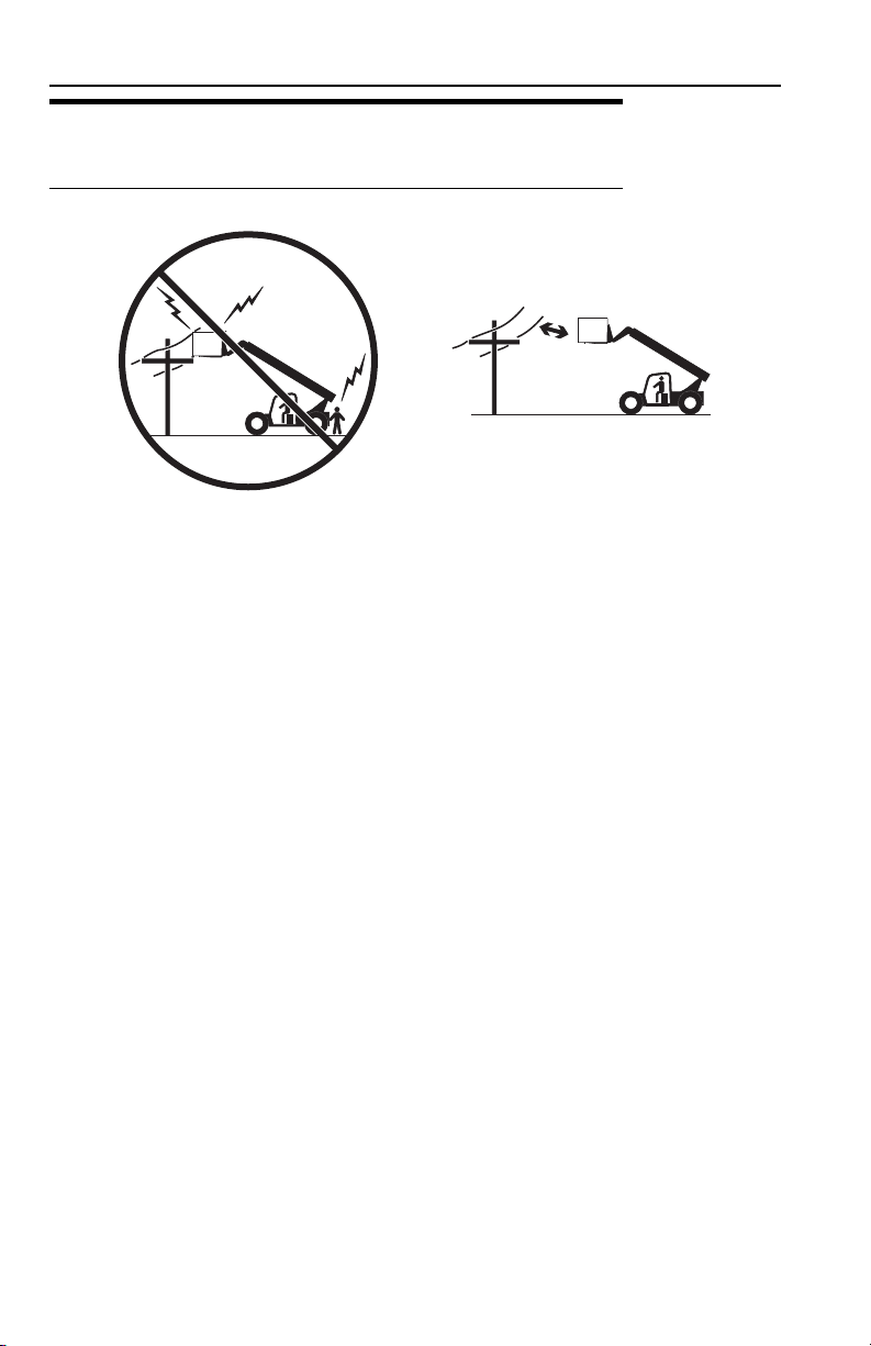
Tip Over Hazard
General
• For additional load requirements, refer to the appropriate capacity chart.
• Never use an attachment without the appropriate JLG approved capacity chart
installed on the telehandler.
• Understand how to properly use the capacity charts located in cab.
• DO NOT exceed rated lift capacity.
• Be sure that the ground conditions are able to support the machine.
• DO NOT raise boom unless frame is level (0 degrees), unless otherwise noted on
capacity chart.
• DO NOT level machine with boom/attachment above 1,2 m (4 ft).
(AUS - DO NOT level machine with load more than 300 mm (11.8 in) above
ground surface.)
1-331200205

Section 1 - General Safety Practices
OH2291
OH
20911
OH2221
• MAINTAIN proper tire pressure at all times. If proper tire pressures are not
maintained, this machine could tip over.
• Refer to manufacturer’s specifications for proper fill ratio and pressure
requirements for tires equipped with ballast.
• Always wear the seat belt.
• Keep head, arms, hands, legs and all other body parts inside operator’s cab at all
times.
If the telehandler starts to tip over:
• DO NOT JUMP
• BRACE YOURSELF and STAY WITH THE MACHINE
• KEEP YOUR SEAT BELT FASTENED
• HOLD ON FIRMLY
• LEAN AWAY FROM THE POINT OF IMPACT
1-4 31200205
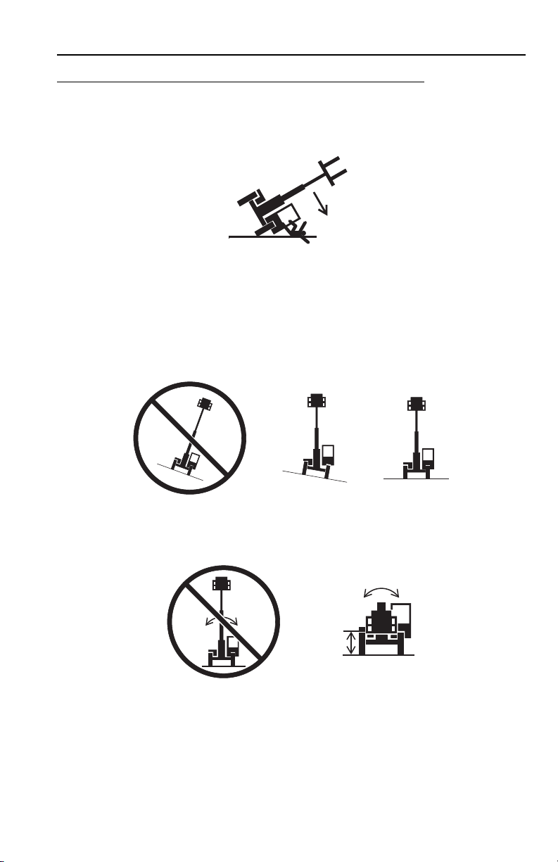
Non-Suspended Load
OW0060
OW0150
• DO NOT drive with boom raised.
Suspended Load
Section 1 - General Safety Practices
• Tether suspended loads to restrict movement.
• Weight of all rigging (slings, etc.) must be included as part of load.
• Beware of wind. Wind can cause a suspended load to swing and cause
dangerous side loads - even with tag lines.
• DO NOT attempt to use telehandler frame-leveling to compensate for load swing.
• Keep heavy part of load closest to attachment.
• Never drag the load; lift vertically.
When driving with a suspended load:
• Start, travel, turn and stop slowly to prevent load from swinging.
• DO NOT extend boom.
• DO NOT raise the load more than 300 mm (11.8 in) above ground surface or
the boom more than 45°.
• DO NOT exceed walking speed.
1-531200205

Section 1 - General Safety Practices
OAL2030
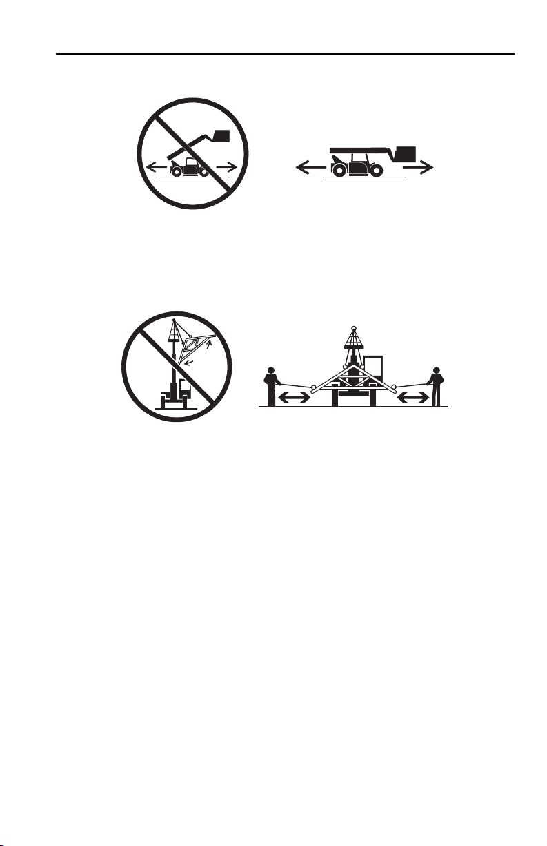
2-Wheel Front Steer 4-Wheel Circle Steer 4-Wheel Crab Steer
Travel Hazard
• Steering characteristics differ between steer modes. Identify the steer mode
settings of the telehandler being operated.
• DO NOT change steer modes while traveling. Steer modes must be changed
while telehandler is stationary.
• Visually verify proper wheel alignment after each steer mode change.
• Ensure that adequate clearance is provided for both rear tail swing and front fork
swing.
• Look out for and avoid other personnel, machinery and vehicles in the area. Use
a spotter if you DO NOT have a clear view.
• Before moving be sure of a clear path and sound horn.
• When driving, retract boom and keep boom/attachment as low as possible while
maintaining visibility of mirrors and maximum visibility of path of travel.
• Always look in the direction of travel.
• Always check boom clearances carefully before driving underneath overhead
obstructions. Position attachment/load to clear obstacles.
• When driving in high speed, use only front wheel steer (if steering modes are
selectable).
1-6 31200205

Section 1 - General Safety Practices
OW0130
Load Falling Hazard
• Never suspend load from forks or other parts of carriage.
• DO NOT burn or drill holes in fork(s).
• Forks must be centered under load and spaced apart as far as possible.
1-731200205

Section 1 - General Safety Practices
OW0170
OW0190
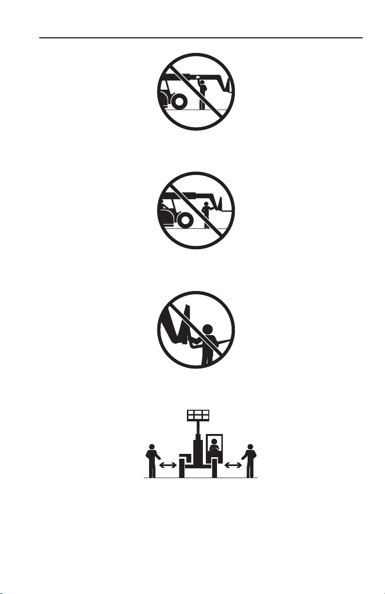
Lifting Personnel
• When lifting personnel, USE ONLY a JLG approved personnel work platform,
with proper capacity chart displayed in the cab.
• DO NOT drive machine from cab when personnel are in platform.
1-8 31200205

Section 1 - General Safety Practices
OW0200
Driving Hazards on Slopes
To maintain sufficient traction and braking capabilities, travel on slopes as follows:
• When unloaded, the rear of the machine is the “heavy end.” Drive with forks
pointed downhill.
• When loaded, the front of the machine is the “heavy end.” Drive with the forks
pointed uphill.
• For additional travel requirements, refer to the appropriate capacity chart.
• To avoid overspeeding the engine and drivetrain when driving down slopes,
downshift to a lower gear and use the service brake as necessary to maintain a
slow speed. DO NOT shift into neutral and coast downhill.
• Avoid excessively steep slopes or unstable surfaces. To avoid tip over DO NOT
drive across excessively steep slopes under any circumstances.
• Avoid turning on a slope. Never engage “inching” or shift to “Neutral” when going
downhill.
• DO NOT park on a slope.
1-931200205

Section 1 - General Safety Practices
OW0210
OW0220
OW0
230
Pinch Points and Crush Hazards
Stay clear of pinch points and rotating parts on the telehandler.
• Stay clear of moving parts while engine is running.
• Keep clear of steering tires and frame or other objects.
• Keep clear from under boom.
1-10 31200205
Section 1 - General Safety Practices
OW0240
OW0250
OW0260
OW0960
• Keep clear of boom holes.
• Keep arms and hands clear of attachment tilt cylinder.
• Keep hands and fingers clear of carriage and forks.
• Keep others away while operating.
1-1131200205

Section 1 - General Safety Practices
OW0280
OW0290
Fall Hazard
• Enter using the proper hand holds and steps provided. Always maintain 3-point
contact when mounting or dismounting. Never grab control levers or steering
wheel when mounting or dismounting the machine.
• DO NOT get off the machine until the shutdown procedure on page 4-3 has been
performed.
• DO NOT carry riders. Riders could fall off machine causing death or serious
injury.
1-12 31200205

Section 1 - General Safety Practices
OW0300
OW0950
Chemical Hazards
Exhaust Fumes
• DO NOT operate machine in an enclosed area without proper ventilation.
• DO NOT operate the machine in hazardous environments unless approved for
that purpose by JLG and site owner. Sparks from the electrical system and the
engine exhaust can cause an explosion.
• If spark arrestors are required, ensure they are in place and in good working
order.
Flammable Fuel
• DO NOT fill the fuel tank or service the fuel system near an open flame, sparks
or smoking materials. Engine fuel is flammable and can cause a fire and/or
explosion.
Hydraulic Fluid
• DO NOT attempt to repair or tighten any hydraulic hoses or fittings while the
engine is running or when the hydraulic system is under pressure.
• Stop engine and relieve trapped pressure. Fluid in the hydraulic system is under
enough pressure that it can penetrate the skin.
• DO NOT use your hand to check for leaks. Use a piece of cardboard or paper to
search for leaks. Wear gloves to protect hands from spraying fluid.
1-1331200205

Section 1 - General Safety Practices
This Page Intentionally Left Blank
1-14 31200205
Section 2 - Pre-Operation and Inspection
OAH1000
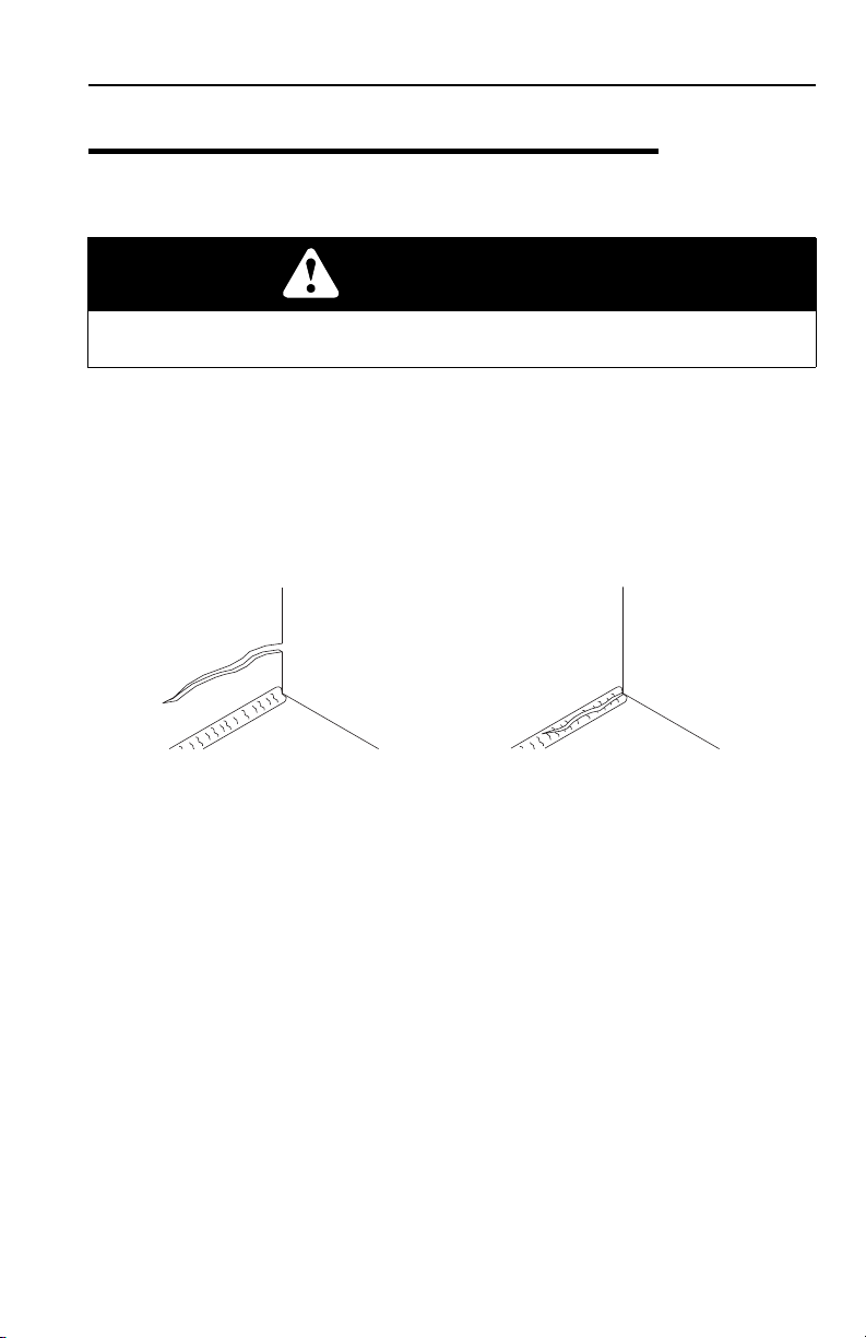
PARENT METAL CRACK WELD CRACK
SECTION 2 - PRE-OPERATION AND INSPECTION
2.1 PRE-OPERATION CHECK AND INSPECTION
Note: Complete all required maintenance before operating unit.
WARNING
FALL HAZARD. Use extreme caution when checking items beyond your normal
reach. Use an approved ladder.
The pre-operation check and inspection, performed at beginning of each work shift
or at each change of operator, should include the following:
1. Cleanliness - Check all surfaces for leakage (oil, fuel or battery fluid) or foreign
objects. Report any leakage to the proper maintenance personnel.
2. Structure - Inspect the machine structure for dents, damage, weld or parent
metal cracks or other discrepancies.
3. Safety Decals - Ensure all safety decals are legible and in place. Clean or
replace as required. See page 2-3 for details.
4. Operation and Safety Manuals - Operation & Safety Manual located in cab
manual holder.
5. Walk-Around Inspection - See page 2-6 for details.
6. Fluid Levels - Check fluids, including fuel, brake fluid, hydraulic oil, engine oil,
transmission fluid and coolant. When adding fluids, refer to Section
7 - Lubrication and Maintenance and Section 9 - Specifications to determine
proper type and intervals. Before removing filler caps or fill plugs, wipe all dirt
and grease away from the ports. If dirt enters these ports, it can severely reduce
component life.
7. Attachments/Accessories - Ensure correct capacity charts are installed on
the telehandler. If provided, reference the Operation & Safety Manual of each
attachment or accessory installed for specific inspection, operation and
maintenance instructions.
2-131200205

Section 2 - Pre-Operation and Inspection
8. Operational Check - Once the walk-around inspection is complete, perform a
warm-up and operational check (see page 2-8) of all systems in an area free of
overhead and ground level obstructions. See Section 3 - Controls and
Indicators for more specific operating instructions.
WARNING
If telehandler does not operate properly, immediately bring machine to a stop,
lower boom and attachment to ground and stop the engine. Determine cause and
correct before continued use.
2-2 31200205
Section 2 - Pre-Operation and Inspection
OZ2122
8006612
8009815
1001094858
(8, 9, 12 & 13M)
8h
2x
50h
1001094858A
OPTIONAL
2999964 (40)
8009377 (35)
2603207 (20)
8009890 (22)
8009885 (12)
35
3700015
50h
1001094925A
2X
8h
8h
1001094925
(17M)
8005869
8008657
OPTIONAL
2999964 (40)
8009377 (35)
2603207 (20)
8009890 (22)
8009885 (12)
8005675
8008657
8005616
37000163700016
8005670
3700016
35
1706227 (CE)
1001102513 (AUS)
8005616
8005617
VIEW A-A
A
A
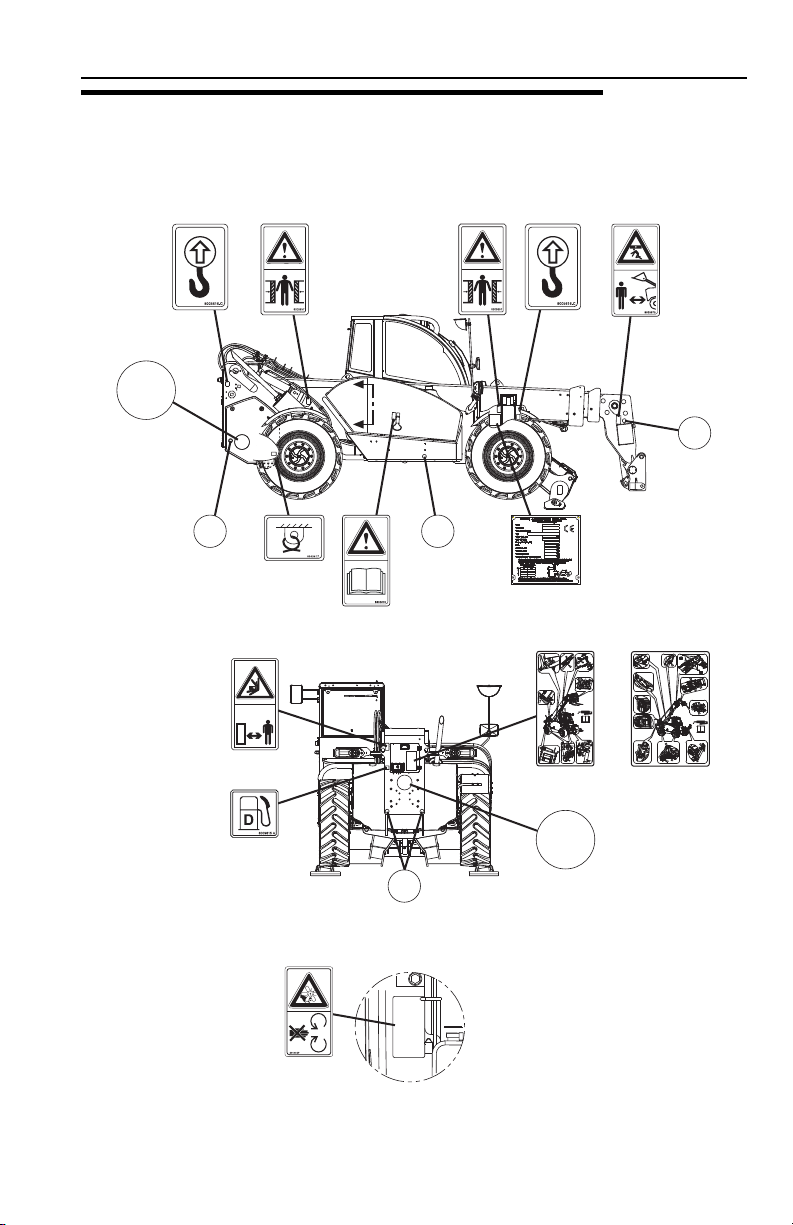
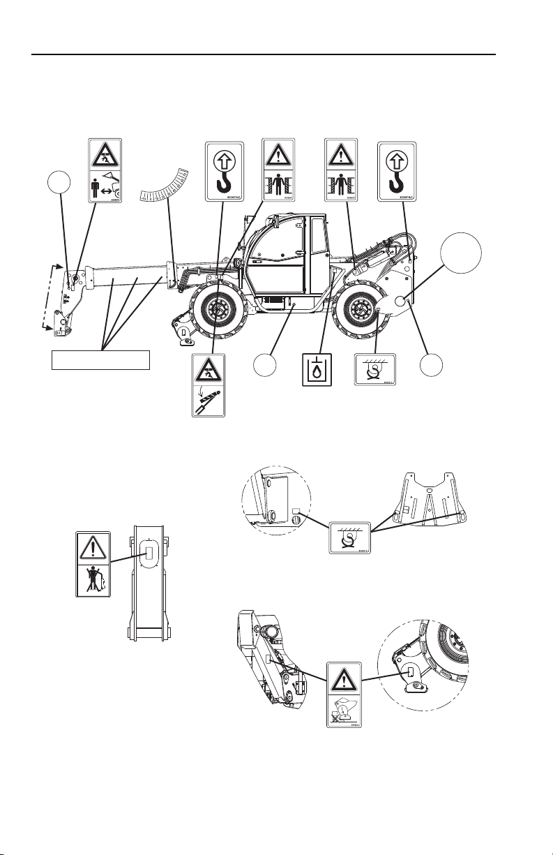
2.2 SAFETY DECALS
Ensure all DANGER, WARNING, CAUTION and instructional decals and proper
capacity charts are legible and in place. Clean and replace as required.
2-331200205
Section 2 - Pre-Operation and Inspection
OZ2131
8006038
8008195
17M12 & 13M
8005617
17M
8, 9, 12 & 13M
8005671
8005671
3700016
Optional
2999964 (40)
8009377 (35)
2603207 (20)
8009890 (22)
8009885 (12)
35
8008657
8005616
8008657
1001094708
1001094708B
3700016
A - 1706753
B - 1706754
C - 1706755
D - 1706756 (12, 13 & 17M)
E - 1706757 (12, 13 & 17M)
F - 1706758 (12, 13 & 17M)
G - 1706759 (13 & 17M)
8005675
8005617
ABC
3700016
ABCDEFG
8005616
1001094171
(AUS)
VIEW B-B
VIEW OF FRONT
TIEDOWN POINTS
B
B
VIEW OF
OUTRIGGERS
2-4 31200205

OZ2145
1001098547
ON OFF
P P
1001098547A
10010991761001103421
12
3
1001103421 A
1705980
L
WA
06
dB
1
1705980
2447967
OIL
ATF
Dexron
D
2447 967
8005670
8008651
F01 7.5 A
F03 7.5 A
F02 15 A
F04 7.5 A
F05 7.5 A
F06 20 A
F07 20 A
F08 7.5 A
F09 15 A
F10 15 A
F11 10 A
F12 15 A
F13 15 A
F14 7.5 A
F15 15 A
F16 15 A
F17 15 A
F18 15 A
F19 7.5 A
F20 15 A
F21 15 A
F22 25 A
F23 10 A
F24 15 A
F25 15 A
F26 10 A
F28 15 A
F27 15 A
F29 15 A
F30 15 A
1001094778A
R
L
R
L
L
R
D
1001094778
1001094900
(LIFT PATTERN)
1001094900B
1001094901
(LOADER PATTERN)
1001094901B
1001094902
(12, 13 & 17M)
1001094902B
1001094713
1001094713A
1001102514
(AUS)
8008746 B
EN 1459 B (1998)
4017
P/N 4802111
P/N 8008014
P/N 1170001
P/N 2340029
4.000kg
3.500kg
3.000kg
2.500kg
2.000kg
1.500kg
1.000kg
500kg
750kg
400kg
0
m
9
0°
10°
20°
30°
40°
50°
60°
70°
A
B
C
D
E
F
G
1
2
3
4
5
6
7
8
9
10
11
12
13
14
876543210
2
0
0
0
k
g
8005870
8005870
1001127546
1001127546 A
VIEW OF PARK
BRAKE LEVER (17M)
LOAD CHARTS
IF EQUIPPED FOR PLATFORM
VIEW OF
REAR WINDOW
VIEW C-C
(8 & 9M S/N 1160005993 & AFTER
INCLUDING 1160005949 & 1160005950)
C
C
Section 2 - Pre-Operation and Inspection
2-531200205

Section 2 - Pre-Operation and Inspection
OZ2152
1
2
4
8
10
13
15
16
7
17
18
19
21
3
7
5
6
9
6
6
6
20
11
12
14
2.3 WALK-AROUND INSPECTION
Begin your walk-around inspection at item 1, as noted below. Continue to your right
(counterclockwise when viewed from top) checking each item in sequence.
INSPECTION NOTE: On all components, make sure there are no loose or missing
parts, that they are securely fastened and no visible leaks or excessive wear exists
in addition to any other criteria mentioned. Inspect all structural members including
attachment for cracks, excessive corrosion and other damage.
1. Boom Sections and Lift, Tilt, Extend/Retract, Compensating (Slave) Cylinders
2. Front Axle
3. Left Outrigger
4. Boom Prop
5. Wheel/Tire Assembly
2-6 31200205
• Check front, top, side and rear wear pads for presence of grease.
• Pivot pins secure; hydraulic hoses undamaged, not leaking.
equipped); hydraulic hoses undamaged, not leaking.
undamaged, not leaking.
nuts. Inspect for worn tread, cuts, tears or other discrepancies.
- Steer cylinders undamaged, not leaking; pivot pins secure (if
(if equipped) - Pins secure; hydraulic hoses and cylinder
(if equipped) - See inspection note.
- Properly inflated and secured; no loose or missing lug
-

Section 2 - Pre-Operation and Inspection
6. Work Lights (if equipped) - Clean and undamaged.
7. Mirrors
- Clean and undamaged.
8. Cab and Electrical
• General appearance; no visible damage.
• Frame level indicator(s) and window glass undamaged and clean.
• Gauges, switches, joystick, foot controls and horn operational.
• Check seat belt for damage, replace belt if frayed or cut webbing, damaged
buckles or loose mounting hardware.
9. Wheel Chock
10. Wheel/Tire Assembly
nuts. Inspect for worn tread, cuts, tears or other discrepancies.
11. Rear Axle
hydraulic hoses undamaged, not leaking.
12. LSI Sensor
13. Wheel/Tire Assembly
nuts. Inspect for worn tread, cuts, tears or other discrepancies.
14. Boom Sensor
1160005950), (17M S/N 1160005937 & After excluding 1160005952,
1160005960, 1160005963, 1160005966 & 1160005978) - See inspection note.
15. Engine Compartment
• Drive belts, check condition and replace as required.
• Engine mounts - See inspection note.
• Air cleaner element condition indicator, check for clogged condition. Replace
element as required.
• Main control valve - See inspection note.
• Battery cables tight, no visible damage or corrosion.
• Engine cover closed and properly secured.
16. Air Precleaner
17. Wheel/Tire Assembly
nuts. Inspect for worn tread, cuts, tears or other discrepancies.
- Steer cylinders undamaged, not leaking; pivot pins secure;
-
(if equipped) - See inspection note.
- Properly inflated and secured; no loose or missing lug
- See inspection note.
- Properly inflated and secured; no loose or missing lug
(8, 9, 12 & 13M S/N 1160005993 & After including 1160005949 &
-
- Check and clean as required.
- Properly inflated and secured; no loose or missing lug
18. Frame Level Cylinder
not leaking.
19. Right Outrigger
undamaged, not leaking.
20. Platform Recognition Sensor
note.
21. Attachment
- Properly installed, see “Attachment Installation” on page 5-11.
(if equipped) - Pins secure; hydraulic hoses undamaged,
(if equipped) - Pins secure; hydraulic hoses and cylinder
(AUS - if equipped for platform): See inspection
2-731200205

Section 2 - Pre-Operation and Inspection
2.4 WARM-UP AND OPERATIONAL CHECKS
Warm-Up Check
During warm-up period, check:
1. Heater, defroster and windshield wiper (if equipped).
2. Check all lighting systems (if equipped) for proper operation.
3. Adjust mirror(s) for maximum visibility.
WARNING
CUT/CRUSH/BURN HAZARD. Keep covers closed while engine is running
except when checking transmission oil level.
Operational Check
When engine warms, perform an operational check:
1. Service brake and parking brake operation.
2. Forward and reverse travel.
3. Each gear.
4. Steering in both directions with engine at low idle (steering lock to lock will not
be reached). Check in each steering mode
5. Horn and back-up alarm. Must be audible from inside operators cab with engine
running.
6. All joystick functions - operate smoothly and correctly.
7. Perform any additional checks described in Section 8.
2-8 31200205

Section 2 - Pre-Operation and Inspection
2.5 OPERATOR CAB
The telehandler is equipped with an enclosed ROPS/FOPS cab.
WARNING
CRUSH HAZARD. Never operate telehandler unless the overhead guard and cab
structure are in good condition. Any modification to this machine must be
approved by JLG to assure compliance with ROPS/FOPS certification for this
cab/machine configuration. If damaged, the CAB CANNOT BE REPAIRED. It
must be REPLACED.
2-931200205

Section 2 - Pre-Operation and Inspection
OZ0211
2
3
1
4
5
OAL1500
2.6 WINDOWS
Keep all windows clean and unobstructed.
Cab Door Window
• Cab door (1) must be closed during operation.
• During operation the cab door window (2) must either be latched open or closed.
• Open the cab door window and secure it in the latch.
• Press the release button (3) inside the cab to unlatch the window.
Rear Window
• Lift lever (4) and push to open the rear window (5).
• Lift lever and pull to close.
2-10 31200205

Section 3 - Controls and Indicators
SECTION 3 - CONTROLS AND INDICATORS
3.1 GENERAL
This section provides the necessary information needed to understand control
functions.
Note: The manufacturer has no direct control over machine application and
operation. The user and operator are responsible for conforming with good safety
practices.
3-131200205

Section 3 - Controls and Indicators
OZ2283
1
2
3
4
5
6
7
8
10
12
13
14
15
16
18
9
11
17
19
3.2 CONTROLS
1. Park Brake: See page 3-11.
2. Accelerator Pedal
speed.
3. Service Brake Pedal
speed.
4. Ignition Switch
5. Hydraulic Quick Attach Switch
to hydraulically lock or unlock an attachment.
6. Power/Emergency Stop Switch
power and stop engine.
7. Auxiliary Power Switch
hold in place to engage auxiliary power. See “Emergency Lowering of Boom If
Equipped for Platform” on page 6-3.
8. Transmission Control Lever
3-2 31200205
: Pressing down the pedal increases engine and hydraulic
: The further the pedal is depressed, the slower the travel
: Key Activated. See page 3-10.
(if equipped for platform): Depress back of switch and
(if equipped): Used in conjuction with the joystick
(if equipped for platform): Push down to shut off
: See page 3-12.

Section 3 - Controls and Indicators
9. Frame Level Indicator: Enables operator to determine the left to right level
condition of the telehandler.
10. Steering Column Adjuster
11. Steering Wheel
machine in the corresponding direction. Three steering modes are available.
See “Steer Modes” on page 3-26.
12. Instrument Panel
13. Accessory Control Lever
14. LSI Indicator
15. Keypad
16. Joystick
17. Longitudinal Level Indicator
to back level condition of the telehandler.
18. Armrest and Right Hand Console
19. Hydraulic Hitch Safety Hook Release
safety hooks on hydraulic hitch. See page 5-46 for control instructions.
: See page 3-8.
: Turning the steering wheel to the left or right steers the
: See page 3-4.
: See page 3-14.
: See page 3-18.
: See page 3-17.
: See page 3-24.
(AUS): Enables the operator to determine the front
: See page 3-22.
(8 & 9M, if equipped): Pull to release
3-331200205

Section 3 - Controls and Indicators
OZ2061
1
2
4
6
7
8
9
10
1112131415161718192021
22
23
24
3
5
Instrument Panel
1. Low Fuel Indicator: Illuminates and buzzer sounds briefly when fuel level is low.
2. Fuel Gauge:
3. Left Turn Signal Indicator
4. Display Screen
5. Right Turn Signal Indicator
6. Engine Temperature Gauge
7. Engine Temperature Warning Indicator
engine temperature is too high.
8. Continuous Auxiliary Hydraulics Indicator
auxiliary hydraulics are active.
9. Trailer Turn Signal Indicator
10. Clutch Lock Indicator
11. High Beam Indicator
12. Anti Theft Indicator
theft feature is active. Enter anti theft code, see page 3-25.
13. Maintenance Indicator
14. Engine Preheat Indicator
15. Park Brake Indicator
3-4 31200205
maintenance is required.
temperature is reached. At temperatures below 0° C (32° F), do not start until
indicator goes out.
Indicates amount of fuel in fuel tank.
: Illuminates when left turn signal is active.
: See page 3-6.
: Illuminates when right turn signal is active.
: Indicates engine operating temperature.
: Illuminates and buzzer sounds when
: Illuminates when continuous
: Illuminates when trailer turn signal is activated.
: Illuminates when clutch lock feature is engaged.
: Illuminates when high beam lights are on.
: Illuminates and buzzer sounds briefly at start-up when anti
: Illuminates and buzzer sounds briefly when
: With ignition key in position II, illuminates until start
: Illuminates when park brake is applied. See page 3-11.

Section 3 - Controls and Indicators
16. System Distress Indicator: Illuminates and buzzer sounds when critical machine
and engine faults exist.
17. Engine Fault Critical Indicator
engine fault exists.
18. Engine Fault Warning Indicator
operating outside the normal range.
19. Air Filter Restriction Indicator
filter(s) require maintenance.
20. Engine Oil Pressure Indicator
pressure is too low.
21. Battery Charge Indicator
system is not functioning properly.
22. Transmission Oil Temperature Indicator
transmission oil temperature is too high.
23. Steering Pressure Indicator
pressure is too low.
24. Hydraulic Filter Restriction Indicator
when hydraulic filter requires maintenance.
: Illuminates and buzzer sounds when a critical
: Illuminates and buzzer sounds when engine is
: Illuminates and buzzer sounds briefly when air
: Illuminates and buzzer sounds when engine oil
: Illuminates when battery is at low charge or charging
: Illuminates and buzzer sounds when
: Illuminates and buzzer sounds when steering
: Illuminates and buzzer sounds briefly
WARNING
EQUIPMENT DAMAGE. When the engine fault, system distress or a red
indicator illuminates (except park brake), immediately bring machine to a stop,
lower boom and attachment to ground and stop the engine. Determine cause and
correct before continued use.
Note: All indicators (except high beam and turn signals) perform a bulb check at
system start up.
3-531200205

Section 3 - Controls and Indicators
OAH1270
8
2
3
4
5
6
7
00
0000
0000
00
F2
RPM
km/h
100
0
00
0000
0000
RPM
km/h
1
DISPLAY SHOWN WITH CONTINUOUS
AUXILIARY HYDRAULICS ACTIVE
DISPLAY SHOWN WITH ANTI THEFT
ACTIVE AT SYSTEM START
Display Screen
1. Joystick Mode: Displays current joystick mode. Joystick mode can be changed
by the machine owner in Operator Tools Menu (level 2 password required). See
Service Manual for information.
a. Loader Joystick Pattern - Displays loader joystick pattern icon on left when
active. See page 3-20.
b. Lift Joystick Pattern - Displays lift joystick pattern icon on right when active.
See page 3-18.
2. Speed and Power to Platform
c. Speed (if equipped) - Telehandler travel speed displayed in kilometers per
hour (km/h) or miles per hour (m/h).
d. Transfer Power to Platform (if equipped for platform) - Assists with
transferring power to platform. Refer to the Platform for 3513PS, 4013PS,
4017PS Operation & Safety Manual.
3. Driving Direction and Gear
a. Direction - Forward (F), Neutral (N) or Reverse (R).
b. Gear - First (1), Second (2), Third (3) or Fourth (4).
4. Engine Speed: Displays engine speed in revolutions per minute (rpm).
:
: Displays current driving condition.
5. Operating Hours
6. Boom Angle
7. Continuous Auxiliary Hydraulics, Steering Mode Change and Platform Status
a. Continuous Auxiliary Hydraulics - Displays flow value (-100% to +100%)
when continuous auxiliary hydraulics is activated. See Section
3-6 31200205
5 - Attachments and Hitches for details.
b. Steering Mode Change - Assists with steering mode change. See “Steer
Modes” on page 3-26 for details.
c. Platform Status (if equipped for platform) - Displays status when platform is
installed.
: Displays total hours of telehandler operation.
: Displays boom angle in degrees. 0 degrees indicates horizontal.
:

Section 3 - Controls and Indicators
OAH2000
MENU:
HELP: PRESS ENTER
9
8. Anti Theft Code Entry: If active, the four digit code must be entered after system
start. See “Anti Theft” on page 3-25 for details.
9. Menus
: Menus display fault codes and other machine information while allowing
modification of some operating parameters. Depress and hold the C and OK
buttons on the keypad to access menus.
a. Help - Displays active fault code. Depress OK button again and use keypad
arrows to cycle through the last 25 fault codes. Active faults are denoted
with an asterisk.
b. Operator Tools - Speed, Temperature and Oil Pressure units and Steering
Alignment Mode can be modified by the operator. Customer or Service level
access code required to modify additional items.
• Machine Speed - Select units (km/h or m/h) to be displayed.
• Engine Temperature - Select units (Celsius or Fahrenheit) to be
displayed.
• Steering Alignment Mode - Select mode (manual or all wheel assisted)
to be used when changing steering modes, see page 3-26.
c. Personalities - View performance parameters. Customer or Service level
access code required to modify parameters.
d. Access Level - Code entry determines access level.
• Operator (Level 3) - No code required.
• Customer (Level 2) - See Service Manual for information.
• Service (Level 1) - Manufacturer service representative only.
e. Diagnostics - View diagnostic information.
f. System Test - Performs test of all system inputs and outputs.
g. Machine Setup - View machine configurations. Service level access code
required to modify configurations.
h. Calibrations - Customer or Service level access code required.
3-731200205

Section 3 - Controls and Indicators
OZ2361
2 31
4
5 6 7
Keypad
1. C (Clear or escape): Use in conjuction with display screen. Returns user
interface one level during navigation. If at top level menu, depress and hold for
one second to exit.
2. Up/Down Arrows
selections and change adjustable values.
3. OK
(Enter): Use in conjuction with display screen. Confirms user interface
inputs.
4. Steer Mode
Steer and 4-Wheel Crab Steer. Illuminated LED indicates current steer mode.
See page 3-26.
: Use in conjuction with display screen. Navigate menu
: Three steer modes available: 4-Wheel Circle Steer, 2-Wheel Front
Note: If machine is shut-down during steer mode change, it must be completed
at restart.
5. LSI Override: Momentarily disables the automatic function cut-out. LED flashes
while activated. Depress and hold up to 30 seconds while operating joystick to
momentarily disable the automatic function cut-out.
WARNING
TIP OVER HAZARD. Exceeding lift capacity of the telehandler could damage the
equipment and/or cause tip over.
6. Bucket Mode
7. Joystick Function
outrigger functions are enabled. Deactivate this function before traveling on
public roads. See “Road Operation (CE)” on page 4-10.
Note: All LEDs perform a bulb check at system start up.
3-8 31200205
: LED lit while activated. Increases response to boom functions.
: LED lit while activated. Boom, auxiliary hydraulics and

Section 3 - Controls and Indicators
This Page Intentionally Left Blank
3-931200205

Section 3 - Controls and Indicators
OZ2300
0
I
II
III
P
Ignition
• Position 0 - Engine off.
• Position I - Voltage available for all electrical functions.
• Position II - Engine preheat at temperatures below 0° C (32° F). Wait to start
engine until preheat indicator on instrument panel goes out.
• Position III - Engine start. In the event the engine does not start, rotate key to
position 0 then back to position III to re-engage the starter.
• Position P (if equipped for platform) - Power transferred to platform.
Note: Key is removable in the 0 and P positions.
3-10 31200205

Section 3 - Controls and Indicators
OZ2290
2
1
3
1
8, 9, 12 & 13M 17M
Park Brake
The park brake lever (1) controls the application and release of the park brake.
• Pull lever back to apply park brake.
• Squeeze release (2) or lift detent ring (3) and push lever forward to release park
brake.
WARNING
MACHINE ROLL-AWAY HAZARD. Always move park brake switch to "ON"
position, lower boom to ground and stop engine before leaving cab.
WARNING
CRUSH HAZARD. Applying park brake while traveling will cause unit to stop
abruptly and could cause load loss. To stop the machine in an emergency, apply
the park brake. 17M Only - Turning engine off also applies the park brake.
Parking Procedure
1. Using service brake, stop telehandler in an appropriate parking area.
2. Follow “Shut-Down Procedure” on page 4-3.
3-1131200205

Section 3 - Controls and Indicators
OZ2310
N
F
R
1
Transmission Control Lever
Direction of Travel Selection
Transmission control lever (1) engages forward or reverse travel.
• Push lever forward for forward travel; pull lever rearward for reverse travel. Move
lever to centered position for Neutral.
• Forward or reverse travel can be selected while in any gear.
• When traveling in reverse, the back-up alarm will automatically sound.
• Drive in reverse and turn only at slow rates of speed.
• If clutch lock switch is activated (see page 3-22), do not increase engine speed
with the transmission in forward or reverse and the service brake depressed in
an attempt to get quicker hydraulic performances. This could cause unexpected
machine movement.
WARNING
TIP OVER/CRUSH HAZARD. Bring telehandler to a complete stop before
shifting transmission control lever. A sudden change in direction of travel could
reduce stability and/or cause load to shift or fall.
3-12 31200205

Section 3 - Controls and Indicators
OZ2320
1st
2nd
3rd
4th
2
Gear Selection
Gear selection is located on the twist grip handle (2) of transmission control lever.
• Twist hand grip to select gear.
• Select the appropriate gear for the task being performed. Use a lower gear
when transporting a load. Use a higher gear only when driving unloaded for
longer distances.
• Slow down prior to downshifting. Do not downshift more than one gear at a
time.
3-1331200205

Section 3 - Controls and Indicators
OZ2340
1
3
4
5
6
7
POWER TEST
2
8
Load Stability Indicator (LSI)
WARNING
TIP OVER HAZARD. The LSI considers only longitudinal stability limitations,
observe all operating parameters. Failure to follow operating parameters of the
telehandler could damage the equipment and/or cause tip over.
8, 9, 12 & 13M Before S/N 1160005993 excluding 1160005949 & 1160005950
17M Before S/N 1160005937 including 1160005952, 1160005960, 1160005963,
1160005966 & 1160005978
The LSI (1) provides visual and audible indication of forward stability limitations
when machine is static on firm, level surface.
• Green LED (2) will illuminate when LSI power is on.
• When approaching forward stability limitations LEDs progressively illuminate,
green (3), then yellow (4) and finally red (5).
• The warning buzzer sounds as the first red LED illuminates.
• As the telehandler reaches forward stability limitations and the second red LED
illuminates, the automatic function cut-out is activated. Certain functions are
disabled (i.e. boom lift, extend, etc). Retract boom to re-enable functions.
• Press button (6) to disable the warning buzzer. When disabled, yellow LED (7)
will illuminate. If last red LED illuminates, disable button is overridden and
warning buzzer sounds.
• Test LSI (8) at the beginning of each work shift. See Section 8 - Additional
Checks.
3-14 31200205

Section 3 - Controls and Indicators
OZ3711
9
15
14
11
12
10
13
8, 9, 12 & 13M S/N 1160005993 & After including 1160005949 & 1160005950
17M S/N 1160005937 & After excluding 1160005952, 1160005960, 1160005963,
1160005966 & 1160005978
The LSI (9) provides visual and audible indication of forward stability limitations
when machine is static on firm, level surface.
• Green LED (10) will illuminate when LSI power is on.
• When approaching forward stability limitations LEDs progressively illuminate,
green (11), then orange (12) and finally red (13).
• If the red LED illuminates the warning buzzer also sounds.
The LSI has two modes:
Active Mode (8, 9, 12, 13 & 17M)
• As the telehandler reaches forward stability limitations and the red LED (13)
illuminates, the automatic function cut-out is activated. All boom, frame level
and outrigger functions are disabled except for boom retract (CE & AUS)
and boom lift (CE). Retract boom to re-enable functions.
• In some instances the LSI system may slow down or stop boom functions if
operated close to forward stability limitations. When LEDs begin to flash,
certain functions can not be operated. Retract boom and/or return the
joystick to neutral position for a short period to allow system to reset and
LEDs to stop flashing before proceeding with operation.
Passive Mode (8 & 9M)
• The orange LED (15) illuminates when either of the following occurs:
• The boom is fully retracted.
• The park brake is not applied and transmission control lever is in the
forward or reverse position.
• When approaching forward stability limitations, visual and audible indication
is provided and the automatic function cut-out and/or slow down feature is
disabled.
3-1531200205

Section 3 - Controls and Indicators
• Travel in accordance with the requirements set forth in Section 1 - General
Safety Practices.
• Test LSI (14) at the beginning of each work shift. See Section 8 - Additional
Checks.
• When placing a load, ensure axles are not fully steered in either direction.
WARNING
TIP OVER HAZARD. If the green, orange and red LEDs flash and warning
buzzer sounds, retract and lower boom immediately. Determine cause and
correct before continued use.
3-16 31200205

Section 3 - Controls and Indicators
OZ2330
1
Steering Column Adjuster
•Follow “Shut-Down Procedure” on page 4-3.
• Turn lever (1) counterclockwise to unlock.
• Place steering column in desired position.
• Turn lever clockwise to lock.
WARNING
TIP OVER/CRUSH HAZARD. Bring telehandler to a complete stop before
shifting transmission control lever. A sudden change in direction of travel could
reduce stability and/or cause load to shift or fall.
3-1731200205

Section 3 - Controls and Indicators
OAH1351
1
2
OZ2490
2
1
5
3
4
12, 13 & 17M
Joystick
Lift Joystick Pattern
Verify the lift joystick pattern icon (2) is active on the display (1) and the joystick
decal located inside the cab matches the machine controls.
The joystick (1) controls the boom, attachment, auxiliary hydraulics and outrigger
functions.
Boom Functions
• Move the joystick back to lift boom; move joystick forward to lower boom; move
joystick right to extend boom; move joystick left to retract boom.
• The speed of boom functions depends upon the amount of joystick travel in
corresponding direction. Increasing engine speed will also increase function
speed.
• For two simultaneous boom functions, move the joystick between quadrants. For
example; moving the joystick forward and to the left will lower and retract boom
simultaneously.
3-18 31200205

Section 3 - Controls and Indicators
WARNING
TIP OVER/CRUSH HAZARD. Rapid, jerky operation of controls will cause rapid,
jerky movement of the load. Such movements could cause the load to shift or fall
or could cause the machine to tip over.
Attachment Functions
Attachment tilt is controlled by the roller switch (2).
• Push the roller switch up to tilt attachment down; push the roller switch down to
tilt attachment up.
Auxiliary Hydraulic Functions
Auxiliary Hydraulics buttons (3 & 4) control functions of attachments that require
hydraulic supply for operation. Buttons (3) can be used simultaneously with normal
boom attachment functions. Button (4) must be used independently of boom lift/
lower functions. See Section 5 - Attachments and Hitches for approved attachments
and control instructions.
Outrigger Functions (12, 13 & 17M)
Button (5) controls both outriggers.
• Press and hold the button; move the joystick forward to lower both outriggers;
move the joystick back to raise both outriggers.
• Press and hold the button; move the joystick left then forward to lower the left
outrigger; move the joystick left then back to raise the left outrigger.
• Press and hold the button; move the joystick right then forward to lower the right
outrigger; move the joystick right then back to raise the right outrigger.
• Outriggers operable with boom below 20 degrees. If equipped with boom
retracted switch, outriggers operable with boom below 20 degrees or with boom
fully retracted and between 20 and 55 degrees.
WARNING
TIP OVER HAZARD. Outriggers increase stability and load capacity only if they
are used properly. Using outriggers on soft surfaces could cause telehandler to
tip over. Always ensure surface can support telehandler and load.
3-1931200205

Section 3 - Controls and Indicators
OAH1381
1
3
OZ2500
2
1
5
3
4
12, 13 & 17M
Loader Joystick Pattern
Verify the loader joystick pattern icon (3) is active on the display (1) and the joystick
decal located inside the cab matches the machine controls.
The joystick (1) controls the boom, attachment, auxiliary hydraulics and outrigger
functions.
Boom Functions
• Move the joystick back to lift boom; move joystick forward to lower boom.
• Extend/retract is controlled by the roller switch (2). Push roller switch up to
extend boom; push roller switch down to retract boom.
• The speed of boom functions depends upon the amount of joystick travel in
corresponding direction. Increasing engine speed will also increase function
speed.
• For two simultaneous boom functions, move the joystick between quadrants. For
example; moving the joystick forward and to the left will lower boom and tilt
attachment up simultaneously.
3-20 31200205

Section 3 - Controls and Indicators
WARNING
TIP OVER/CRUSH HAZARD. Rapid, jerky operation of controls will cause rapid,
jerky movement of the load. Such movements could cause the load to shift or fall
or could cause the machine to tip over.
Attachment Functions
Attachment tilt is controlled by the joystick.
• Move joystick right to tilt down; move joystick left to tilt up.
Auxiliary Hydraulic Functions
Auxiliary Hydraulics buttons (3 & 4) control functions of attachments that require
hydraulic supply for operation. Buttons (3) can be used simultaneously with normal
boom attachment functions. Button (4) must be used independently of boom lift/
lower functions. See Section 5 - Attachments and Hitches for approved attachments
and control instructions.
Outrigger Functions (12, 13 & 17M)
Button (5) controls both outriggers.
• Press and hold the button; move the joystick forward to lower both outriggers;
move the joystick back to raise both outriggers.
• Press and hold the button; move the joystick left then forward to lower the left
outrigger; move the joystick left then back to raise the left outrigger.
• Press and hold the button; move the joystick right then forward to lower the right
outrigger; move the joystick right then back to raise the right outrigger.
• Outriggers operable with boom below 20 degrees. If equipped with boom
retracted switch, outriggers operable with boom below 20 degrees or with boom
fully retracted and between 20 and 55 degrees.
WARNING
TIP OVER HAZARD. Outriggers increase stability and load capacity only if they
are used properly. Using outriggers on soft surfaces could cause telehandler to
tip over. Always ensure surface can support telehandler and load.
3-2131200205

Section 3 - Controls and Indicators
OZ2420
14
15
16
17
1
2
3
4
5
7
8
9
10
11
12
13
6
Armrest and Right Hand Console
1. Frame Level Switch (if equipped): Controls the left to right frame level. Depress
right side of switch to rotate frame right; depress left side of switch to rotate
frame left. Frame level operable with boom below 20 degrees. If equipped with
boom retracted switch, frame level operable with boom below 20 degrees or
with boom fully retracted and between 20 and 55 degrees.
2. Hazard Light Switch: On/Off switch.
3. Beacon Light Switch
beacon on cab roof. Power supplied by 12V receptacle at rear left of cab roof.
4. Clutch Lock Switch
engaged while depressing service brake. Depress back of switch to deactivate
system and have transmission disengage while depressing service brake.
5. Boom Work Lights Switch
6. Front/Rear Auxiliary Hydraulics Switch
auxiliary hydraulics. Depress back of switch to activate rear auxiliary hydraulics.
7. Rear Wiper Switch
8. Driving Lights Switch
(if equipped): On/Off switch. Place magnetic base of
: Depress front of switch to activate and keep transmission
(if equipped): On/Off switch.
: Depress front of switch to activate front
: On/Off switch.
(if equipped): On/Off switch.
9. Rear Work Lights Switch
10. Front Work Lights Switch
11. Power Outlet
12. Auxiliary Electrics
auxiliary electric feature. See Section 5 - Attachments and Hitches for approved
attachments and control instructions.
: 12V receptacle.
3-22 31200205
(if equipped): On/Off switch.
(if equipped): On/Off switch.
(if equipped): On/Off switch. Depress button to activate

Section 3 - Controls and Indicators
13. Continuous Auxiliary Hydraulics Switch:
a. Depress and release front of switch for continuous operation of hydraulic
powered attachments. Set continuous auxiliary hydraulic level (-100% to
100%) within 10 seconds using the keypad up/down arrow buttons (see
page 3-8). See Section 5 - Attachments and Hitches for approved
attachments and control instructions.
b. Relieves auxiliary hydraulic circuit pressure. See page 5-18.
Heater and Air Conditioning Controls
14. Fan Speed Switch
15. Recycle/Fresh Air Switch
: Adjustable rotary switch.
(if equipped): Adjustable rotary switch.
16. Temperature Control Switch
17. Air Conditioning Switch
(if equipped): On/Off switch.
: Adjustable rotary switch.
3-2331200205

Section 3 - Controls and Indicators
OZ3450
1
2
3
4
OZ3460
1
5
6
I
O
J
7
Accessory Control Lever
Turn Signals and Low/High Beam Headlights
• Push accessory control lever (1) forward (2) to activate left turn signal.
• Pull lever backward (3) to activate right turn signal.
• The lever must be manually returned to the center position to deactivate either
turn signal. The lever will not cancel automatically after a turn.
• Pull lever up (4) to switch between low and high beam headlights.
Front Windshield Wiper and Horn
• Rotate hand grip (5) to activate front windshield wiper, O - Off, J - Continuous or
I - Fast
• Depress end of lever (6) to activate windshield wiper fluid.
• Depress button (7) to sound horn.
3-24 31200205

Section 3 - Controls and Indicators
OAH1430
2 3
1
0
00
0000
0000
RPM
km/h
3.3 ANTI THEFT
Machines with the anti theft feature active require entering a numeric code before
operation to prevent unauthorized use. Code entry is accomplished using the display
and keypad.
1. Turn ignition switch to position I. If anti theft is active, the display (1) will prompt
the operator for a numeric code.
2. Use the up/down arrow buttons (2) to select the first digit.
3. Depress OK button (3) to confirm and move to the next digit.
4. Continue until the code is complete.
5. If an incorrect code is entered, the buzzer will sound briefly and the display will
prompt the operator again for the numeric code.
Note: If the anti theft feature is active and the current access code is not known, it
may be viewed or changed by the machine owner in Operator Tools Menu (level 2
password required). See Service Manual for information.
6. If the correct code is entered, normal start up can continue.
3-2531200205

Section 3 - Controls and Indicators
OAL2030
2-Wheel Front Steer 4-Wheel Circle Steer 4-Wheel Crab Steer
OAM2381
1 2 3
OAM2400
4 5
3.4 STEER MODES
Three steer modes are available for operator use.
Note: 2-Wheel Front Steer mode is required for travel on public roads.
Manual Steering Alignment Mode Change
If manual steering alignment mode is active under the Operator Tools menu (see
page 3-7), use the following procedure for steer mode change.
Note: Steer mode will change immediately after selection.
1. Bring machine to a stop using service brake. If front steer mode (2) is active and
rear wheels are aligned, go directly to step 4.
2. With circle steer (1) or crab steer (3) mode active, turn the steering wheel until
the left rear wheel (4) is aligned with the side of the machine.
3. Select front steer mode (2).
4. Turn the steering wheel until the left front wheel (5) is aligned with the side of
the machine.
5. Wheels are now aligned. Select desired steer mode.
3-26 31200205

Section 3 - Controls and Indicators
OAM2381
1 2 3
OAM2391
6 7 8
00
0000
0000
00
F1
RPM
km/h
00
0000
0000
00
F1
RPM
km/h
00
0000
0000
00
F1
RPM
km/h
All Wheel Assisted Steering Alignment Mode Change
If all wheel assisted steering alignment mode is active under the Operator Tools
menu (see page 3-7), use the following procedure for steer mode change.
1. Bring machine to a stop using service brake.
2. Select desired steer mode: circle steer (1), front steer (2) or crab steer (3).
Note: Selected steer mode LED will flash and display will show steering alignment
screens until the change is complete. After steering alignment is complete, steer
mode LED will illuminate solid.
3. Turn the steering wheel until the rear wheels are centered (6). This step will be
skipped if changing from front steer mode and rear wheels are already
centered.
4. Turn the steering wheel until the front wheels are centered (7). This step will be
skipped if changing to front steer mode.
5. Wheels are now aligned and steer mode change is complete (8).
3-2731200205

Section 3 - Controls and Indicators
OAH1471
1
2
3
4
5
6
7
7
3.5 OPERATOR SEAT
Adjustments
Prior to starting the engine adjust seat for position and comfort.
Mechanical Suspension Seat
1. Backrest: Use handle to adjust backrest angle.
2. Fore/Aft
3. Suspension
4. Weight
5. Lumbar Support
6. Seat Belt
7. Height
: Use handle to move seat fore and aft.
: Use handle to adjust suspension to the appropriate weight setting.
: Displays current weight setting.
: Use knob to adjust lumbar support.
: Always fasten seat belt during operation.
: Pull up on both sides of seat to adjust height.
3-28 31200205

Pneumatic Suspension Seat
OAH1481
1
2
5
6
3
4
7
Section 3 - Controls and Indicators
1. Backrest Angle
2. Fore/Aft
3. Suspension
4. Height
: Use handle to move seat fore and aft.
: Use knob to adjust suspension to the appropriate weight setting.
: Use knob to adjust height to the appropriate setting.
5. Lumbar Support
6. Seat Belt
: Always fasten seat belt during operation.
7. Fore/Aft Isolator
: Use handle to adjust backrest angle.
: Use knob to adjust lumbar support.
: Use handle to lock or unlock.
3-2931200205

Section 3 - Controls and Indicators
OH20912
Seat Belt
Fasten seat belt as follows:
1. Grasp both free ends of the belt making certain that belt webbing is not twisted
or entangled.
2. With back straight in the seat, couple the retractable end (male end) of the belt
into the receptacle (buckle) end of the belt.
3. With belt buckle positioned as low on the body as possible, pull the retractable
end of the belt away from the buckle until it is tight across the lap.
4. To release belt latch, depress red button on the buckle and pull free end from
buckle.
3-30 31200205

Section 3 - Controls and Indicators
OZ2411
1
2
3.6 BOOM INDICATORS
Boom Extension
• The boom extension indicators (1) are located on the left side of the boom. Use
these indicators to determine boom extension when using the capacity chart (see
“Use of the Capacity Chart” on page 5-5).
Boom Angle (AUS)
• The boom angle indicator (2) is located on the left side of the boom. Use this
indicator to determine boom angle when using the capacity chart (see “Use of
the Capacity Chart” on page 5-5).
3-3131200205

Section 3 - Controls and Indicators
This Page Intentionally Left Blank
3-32 31200205

Section 4 - Operation
SECTION 4 - OPERATION
4.1 ENGINE
Starting the Engine
This machine can be operated under normal conditions in temperatures of -18°C to
45°C (0°F to 113°F). Consult JLG for operation outside this range or under abnormal
conditions.
1. Make sure all controls are in “Neutral” and all electrical components (lights,
heater, defroster, etc.) are turned off. Set parking brake.
2. If equipped for platform, pull the power/emergency stop switch up.
3. Turn ignition switch to position I. If active, enter anti theft code.
4. Turn ignition switch to position II. If the temperature is below 0° C (32° F), wait
for preheat indicator on instrument panel to go out.
5. Turn ignition switch to position III to engage starting motor. Release key
immediately when engine starts. If engine fails to start within 20 seconds,
release key and allow starting motor to cool for a few minutes before trying
again.
6. After engine starts, observe engine oil pressure indicator. If indicator remains
on for more than five seconds, stop engine and determine cause before
restarting engine.
7. Warm up engine at approximately 1/2 throttle.
Note: Engine will not start unless transmission control lever is in “Neutral” and park
brake is applied.
WARNING
UNEXPECTED MOVEMENT HAZARD. Always ensure that transmission control
lever is in neutral and the service brake is applied before releasing park brake.
Releasing park brake in either forward or reverse could cause the machine to
move abruptly.
WARNING
ENGINE EXPLOSION. Do not spray ether into air intake for cold weather
starting.
4-131200205

Section 4 - Operation
OW0530
Battery Boosted Starting
If battery-boost starting (jump-start) is necessary, proceed as follows:
• Never allow vehicles to touch.
• Ensure boosting vehicle engine is running.
• Connect the positive (+) jumper cable to positive (+) post of discharged battery.
• Connect the opposite end of positive (+) jumper cable to positive (+) post of
booster battery.
• Connect the negative (-) jumper cable to negative (-) post on booster battery.
• Connect opposite end of negative (-) jumper cable to ground point on machine
away from discharged battery.
• Follow standard starting procedures.
• Remove cables in reverse order after machine has started.
WARNING
BATTERY EXPLOSION HAZARD. Never jump start or charge a frozen battery
as it could explode. Keep sparks, flames and lighted smoking materials away
from the battery. Lead acid batteries generate explosive gases when charging.
Wear safety glasses.
4-2 31200205

Section 4 - Operation
Normal Engine Operation
• Observe instrument panel and display frequently to be sure all systems are
functioning properly.
• Be alert for unusual noises or vibration. When an unusual condition is
noticed, park machine in safe position and perform shut-down procedure. Report
condition to your supervisor or maintenance personnel.
• Avoid prolonged idling. If the engine is not being used, turn it off.
Shut-Down Procedure
When parking the telehandler, park in a safe location on flat level ground and away
from other equipment and/or traffic lanes.
1. Apply the park brake.
2. Shift the transmission to “Neutral.”
3. Lower forks or attachment to the ground.
4. Operate engine at low idle for 3 to 5 minutes. DO NOT over rev engine.
5. Shut off engine and remove ignition key.
6. Push power/emergency stop switch down (if equipped for platform).
7. Exit telehandler properly.
8. Turn off electrical master switch (if equipped).
9. Block wheels (if necessary).
4-331200205

Section 4 - Operation
4.2 OPERATING WITH A NON-SUSPENDED LOAD
Lift Load Safely
• You must know the weight and load center of every load you lift. If you are not
sure of the weight and load center, check with your supervisor or with the
supplier of the material.
WARNING
TIP OVER HAZARD. Exceeding lift capacity of the telehandler could damage the
equipment and/or cause tip over.
• Know the rated load capacities (refer to Section 5 - Attachments and Hitches) of
the telehandler to determine the operating range in which you can safely lift,
transport and place a load.
Picking Up a Load
• Note the conditions of the terrain. Adjust travel speed and reduce amount of load
if conditions warrant.
• Avoid lifting double-tiered loads.
• Make sure load is clear of any adjacent obstacles.
• Adjust spacing of forks so they engage the pallet or load at maximum width. See
“Adjusting/Moving Forks” on page 5-19.
• Approach load slowly and squarely with fork tips straight and level. NEVER
attempt to lift a load with just one fork.
• NEVER operate telehandler without a proper and legible capacity chart in the
operator cab for the telehandler/attachment combination you are using.
4-4 31200205

Section 4 - Operation
OW0540
Transporting a Load
• After engaging the load and resting it against the backrest, tilt the load back to
position it for travel. Travel in accordance with the requirements set forth in
Section 1 - General Safety Practices and Section 5 - Attachments and Hitches.
Leveling Procedure
1. Position machine in best location to lift or place load.
2. Apply parking brake and move transmission control lever to NEUTRAL.
3. Observe level indicator(s) to determine whether machine must be leveled prior
to lifting load.
4. Move boom/attachment to 1,2 m (4 ft) off ground.
(AUS - Move boom so forks are no more than 300 mm (11.8 in) above ground
surface.)
Important things to remember:
• Never raise the boom/attachment more than 1,2 m (4 ft) above ground unless
telehandler is level.
(AUS - Never raise the forks more than 300 mm (11.8 in) above ground surface
unless telehandler is level.)
• The combination of frame leveling and load could cause the telehandler to tip
over.
4-531200205

Section 4 - Operation
Placing a Load
Before placing any load be sure that:
• The landing point can safely support the weight of the load.
• The landing point is level; front to back and side to side.
• Use the capacity chart to determine safe boom extension range. See “Use of the
Capacity Chart” on page 5-5.
• Align forks at the level load is to be placed, then extend boom slowly until load is
just above area where it is to be placed.
• Lower the boom until the load rests in position and the forks are free to retract.
Disengaging a Load
Once the load has been placed safely at the landing point, proceed as follows:
1. With the forks free from the weight of the load, the boom can be retracted
and/or the telehandler can be backed away from under the load if surface will
not change level condition of telehandler.
2. Lower the carriage.
3. The telehandler can now be driven from the landing location to continue work.
4-6 31200205

Section 4 - Operation
4.3 OPERATING WITH A SUSPENDED LOAD
Lift Load Safely
• You must know the weight and load center of every load you lift. If you are not
sure of the weight and load center, check with your supervisor or with the
supplier of the material.
WARNING
TIP OVER HAZARD. Exceeding lift capacity of the telehandler could damage the
equipment and/or cause tip.
• Know the rated load capacities (refer to Section 5 - Attachments and Hitches) of
the telehandler to determine the operating range in which you can safely lift,
transport and place a load.
Picking Up a Suspended Load
• Note the conditions of the terrain. Adjust travel speed and reduce amount of load
if conditions warrant.
• Avoid lifting double-tiered loads.
• Make sure load is clear of any adjacent obstacles.
• NEVER operate telehandler without a proper and legible capacity chart in the
operator cab for the telehandler/attachment combination you are using.
• Only use approved lifting devices rated for the lifting of the load.
• Identify the proper lifting points of the load, taking into consideration the center of
gravity and load stability.
• Ensure to always properly tether loads to restrict movement.
• Refer to “Use of the Capacity Chart” on page 5-5 for proper lifting guidelines in
addition to the appropriate capacity chart in the operator cab.
4-731200205

Section 4 - Operation
OW0130
OZ3160
Transporting a Suspended Load
• Travel in accordance with the requirements set forth in Section 1 - General
Safety Practices and Section 5 - Attachments and Hitches.
• For additional requirements, refer to the appropriate capacity chart in the
operator cab.
Important things to remember:
• Ensure the boom is fully retracted.
• Never raise the load more than 300 mm (11.8 in) above ground surface or the
boom more than 45°.
• The combination of frame leveling and load could cause the telehandler to tip
over.
• The guide persons and operator must remain in constant communication (verbal
or hand) and be in visual contact with the operator at all times.
• Never place the guide persons between the suspended load and the telehandler.
• Only transport the load at walking speed (0.4 m/s) or less.
Leveling Procedure
1. Position machine in best location to lift or place load.
2. Apply parking brake and move transmission control lever to NEUTRAL.
3. Observe level indicator(s) to determine whether machine must be leveled prior
to lifting load.
4. Move boom so load is no more than 300 mm (11.8 in) above ground surface
and/or boom is raised no more than 45°.
4-8 31200205

Section 4 - Operation
Placing a Suspended Load
Before placing any load be sure that:
• The landing point can safely support the weight of the load.
• The landing point is level; front to back and side to side.
• Use the capacity chart to determine safe boom extension range. See “Use of the
Capacity Chart” on page 5-5.
• Align load at the level load is to be placed, then position boom slowly until load is
just above area where it is to be placed.
• Ensure that the guide persons and operator remain in constant communication
(verbal or hand) when placing the load.
Disengaging a Suspended Load
• Never place the guide persons between the suspended load and the telehandler.
• Once at the destination of the load, ensure to bring the telehandler to a complete
stop and apply the park brake prior to disengagement of the lifting devices and
the tethers.
4-931200205

Section 4 - Operation
OZ2171
1 2
4.4 ROAD OPERATION (CE)
1. Preparation
a. Remove load from attachment.
b. Remove any large amounts of dirt from machine.
c. Check lights and mirrors and adjust if necessary.
Note: Be sure to follow all local and federal/provincial traffic regulations.
2. Lower boom. Front edge of attachment should be approximately 30-40 cm
(12-16 in) above the ground.
3. Fully tilt attachment back.
4. Place protective shield over front bucket edge: remove or reposition carriage
forks toward the machine and secure to the carriage.
5. Depress button (2) to deactivate joystick function and disable all joystick
controlled functions. Joystick function LED will go out.
6. Deactivating the joystick function automatically changes steer mode to front
wheel steering (1). See “Steer Modes” on page 3-26 for details.
7. Machine is now ready for road operation.
4-10 31200205

Section 4 - Operation
OZ2180
4.5 LOADING AND SECURING FOR TRANSPORT
Tiedown
1. If equipped, level the telehandler prior to loading.
2. Using a spotter, load the telehandler with boom as low as possible.
3. Once loaded, apply parking brake and lower boom until boom or attachment is
resting on deck. Move all controls to “Neutral,” stop engine and remove ignition
key.
4. Secure machine to deck by passing chains through the designated tiedown
points as shown in the figure.
5. Do not tiedown front of boom.
Note: The user assumes all responsibility for choosing the proper method of
transportation and tie-down devices, making sure the equipment used is capable of
supporting the weight of the vehicle being transported and that all manufacturer’s
instructions and warnings, regulations and safety rules of their employer and all local
and federal/provincial laws are followed.
WARNING
TELEHANDLER SLIDE HAZARD. Before loading telehandler for transport,
make sure deck, ramps and telehandler wheels are free of mud, snow and ice.
Failure to do so could cause telehandler to slide.
4-1131200205

Section 4 - Operation
Lifting
• When lifting machine, it is very important that the lifting device and equipment is
attached only to designated lifting points. If machine is not equipped with lifting
lugs contact JLG Product Safety for information.
• Make adjustments to the lifting device and equipment to ensure the machine will
be level when elevated. The machine must remain level at all times while being
lifted.
• Ensure that the lifting device and equipment is adequately rated and suitable for
the intended purpose. See Section 9 - Specifications for machine weight or
weigh machine.
• Remove all loose items from machine prior to lifting.
• Lift machine with smooth, even motion. Set machine down gently. Avoid quick or
sudden motions that could cause shock loads to machine and/or lifting devices.
4-12 31200205

Section 5 - Attachments and Hitches
SECTION 5 - ATTACHMENTS AND HITCHES
5.1 APPROVED ATTACHMENTS
To determine if an attachment is approved for use on the specific telehandler you are
using, perform the following prior to installation.
• The attachment model/option number on the attachment identification plate must
match the attachment number on a capacity chart located in the operator cab.
• The model on the capacity chart must match the model telehandler being used.
• The load center of the fork (if equipped) must match the load center as indicated
on the capacity chart.
• Hydraulically powered attachments must only be used on machines equipped
with auxiliary hydraulics.
If any of the above conditions are not met, do not use the attachment. The
telehandler may not be equipped with the proper capacity chart or the attachment
may not be approved for the model telehandler being used. Contact JLG or the local
distributor for further information.
5.2 UNAPPROVED ATTACHMENTS
Do not use unapproved attachments for the following reasons:
• Range and capacity limitations for “will fit,” homemade, altered, or other
non-approved attachments cannot be established.
• An overextended or overloaded telehandler can tip over with little or no warning
and cause serious injury or death to the operator and/or those working nearby.
• The ability of a non-approved attachment to perform its intended function safely
cannot be assured.
WARNING
Use only approved attachments. Attachments which have not been approved for
use with your telehandler could cause machine damage or an accident.
5-131200205

Section 5 - Attachments and Hitches
5.3 JLG SUPPLIED ATTACHMENTS
3508PS, 3509PS, 3512PS, 4008PS, 4009PS & 4012PS
Applicable Standard
3508PS
4008PS
CE CE AUS CE
Attachment
Part
Number
Carriage, 1185 mm 1170028 XXXX
Carriage, 1185 mm 1001107333 X X X
Carriage, 1185 mm 1001107581 X
Side Shift Carriage, 1200 mm 1170002 X X X
Fork, 50x100x1200 mm 2340030 XXXX
Fork, Narrow 50x100x1200 mm 2340041 XXXX
Fork, 50x100x1200 mm 1001100911 X X X
Fork, 60x100x1200 mm 1001107586 X
Fork Extension, 50x100 mm 1001112559 XXXX
Fork Extension, 60x100 mm 1001112560 X
Bucket, 0,51 m
Bucket, 0,9 m
Bucket, 1,0 m
Bucket, 1,8 m
Bucket, 2,0 m
3
3
3
3
3
Bucket with Teeth, 0,8 m
Bucket with Teeth, 1,0 m
Bucket, Multi-Purpose, 1,0 m
Bucket, Multi-Purpose
Bucket, Grapple, 0,8 m
3
Fork Mounted Concrete Bucket,
500L
1001145722 X
0930015 XXXX
1001145724 X
0930016 XXXX
1001145725 X
3
3
4805670 X
4802100 XXXX
3
0930003 XXXX
1001128891 X
1001145723 X
0930004 X X X
0240158 X X X
Concrete Bucket Mixer, 500 L 1001106930 X X
Truss Boom, 3,4 m 0240063 X X X
Truss Boom, 3,6 m 0240110 X X X
Truss Boom, 2,0 m 1001101442 X
Fork Mounted Hook 2700118 X X X
3509PS
4009PS
3512PS
4012PS
5-2 31200205

3513PS, 4013PS & 4017PS
Section 5 - Attachments and Hitches
Applicable Standard
Attachment
Part
Number
3513PS
4013PS
CE AUS CE AUS JLG Manitou
4017PS
Carriage, 1185 mm 1170028 XXXX X
Carriage, 1185 mm 1001107333 X X X
Carriage, 1185 mm 1001107581 X X X
Carriage, 1200 mm 1001102553 X X X
Side Shift Carriage, 1200 mm 1170002 X X X
Fork Positioning Carriage, 1225 mm 1001091313 X X X
Fork, 50x100x1200 mm 2340030 XXXX X
Fork, Narrow 50x100x1200 mm 2340041 XXXX X
Fork, 50x100x1200 mm 1001100911 X X X
Fork, 60x100x1200 mm 1001107586 X X X
Fork Extension, 50x100 mm 1001112559 XXXX X
Fork Extension, 60x100 mm 1001112560 X X X
Bucket, 0.51 m
Bucket, 0,9 m
Bucket, 1,0 m
Bucket, 1,8 m
Bucket, 2,0 m
3
3
3
3
3
Bucket with Teeth, 0,8 m
Bucket with Teeth, 1,0 m
Bucket, Multi-Purpose, 1,0 m
Bucket, Multi-Purpose
Fork Mounted Concrete Bucket,
500L
1001145722 X X X
0930015 XXXX X
1001145724 X X X
0930016 XXXX X
1001145725 X X X
3
3
4805670 X X X
4802100 XXXX X
3
0930003 XXXX X
1001128891 X X X
1001145723 X X X
0240158 X X X
Concrete Bucket Mixer, 500 L 1001106930 X X X
Truss Boom, 3,4 m 0240063 X X X
Truss Boom, 3,6 m 0240110 X X X
Truss Boom, 2,0 m 1001101442 X X X
Fork Mounted Hook 2700118 X X X
Quick Attach Mounted Hook 1170058 X X X
1001097353 X X X
Platform, 1,8 m
1001112107 X X X
1001114460 X X X
1001097355 X X X
Platform, 4,5 m
1001112108 X X X
1001114462 X X X
Quick
Attach
5-331200205

Section 5 - Attachments and Hitches
3
2
1
OZ0810
5.4 TELEHANDLER/ATTACHMENT/FORK CAPACITY
Prior to installing the attachment verify it is approved and the telehandler is equipped
with the proper capacity chart. See “Approved Attachments” on page 5-1.
To determine the maximum capacity of the telehandler and attachment, use the
smallest of the following capacities:
• Capacity stamped on the attachment identification plate (1).
• Fork capacities and load centers are stamped on the side of each fork (2)
(if equipped). This rating specifies the maximum load capacity that the individual
fork can safely carry at the maximum load center (3). Total attachment capacity is
multiplied by the number of forks on the attachment (if equipped), up to the
maximum capacity of the attachment.
• Maximum capacity as indicated on the proper capacity chart. See “Approved
Attachments” on page 5-1.
• When the load rating of the telehandler differs from the capacity of the forks or
attachment, the lower value becomes the overall load capacity.
Use the proper capacity chart to determine maximum capacity at various machine
configurations. Lifting and placing a load may require use of more than one capacity
chart based on machine configuration.
Other than block forks, all forks should be used in matched pairs, block forks used in
matched sets.
WARNING
Never use an attachment without the appropriate JLG approved capacity chart
installed on the telehandler.
5-4 31200205

Section 5 - Attachments and Hitches
OZ1702
AB
BOOM
EXTENSION
INDICATOR
FORK
WEIGHT
STAMP
BOOM ANGLE
INDICATOR
(inside cab)
ATTACHMENT
IDENTIFICATION
PLATE
BOOM ANGLE
INDICATOR
(AUS)
5.5 USE OF THE CAPACITY CHART
To properly use the capacity chart (see page 5-6), the operator must first determine
and/or have the following:
1. An approved attachment. See “Approved Attachments” on page 5-1.
2. The proper Capacity Chart.
3. Weight of the load being lifted.
4. Load placement information:
a. HEIGHT where the load is to be placed.
b. DISTANCE from the front tires of the telehandler where the load is to be
placed.
5. On the capacity chart, find the line for the height and follow it over to the
distance.
6. The number in the load zone where the two cross is the maximum capacity for
this lift. If the two cross at a division between zones, the smaller number must
be used.
The number in the load zone must be equal to or greater than the weight of the load
to be lifted. Determine the limits of the load zone on the capacity chart and keep
within these limits.
Capacity Indicator Locations
5-531200205

Section 5 - Attachments and Hitches
XXXXXXX
EN 1459 B (1998)
XXXX
P/N 1122334
P/N 9988776
P/N 1234567
P/N 9876543
4.000kg
3.500kg
3.000kg
2.500kg
2.000kg
1.500kg
1.000kg
500kg
750kg
400kg
0
m
9
0°
10°
20°
30°
40°
50°
60°
70°
A
B
C
D
E
F
G
1
2
3
4
5
6
7
8
9
10
11
12
13
14
876543210
2000kg
OZ0640
Boom Extension
Indicator (arc)
Load zones indicate
the maximum weight
that may be safely lifted.
These numbers must match the
model/option number stamped
on the attachment ID Plate.
Boom Angle
This Capacity Chart may be used with this model ONLY.
The telehandler model is indicated on the boom or chassis.
Model XXXX is used for demonstration purposes only.
Sample Capacity Chart (CE)
Note: This is a sample capacity chart only! DO NOT use this chart, use the one
located in your operator cab.
TIP OVER HAZARD. All loads shown on rated capacity chart are based on
machine being on firm ground with frame level (see page 4-5); the forks being
positioned evenly on carriage; the load being centered on forks; proper size tires
being properly inflated; and the telehandler being in good operating condition.
5-6 31200205
WARNING

Section 5 - Attachments and Hitches
OW0930
OW0940
To identify the proper capacity chart on telehandlers equipped with outriggers, refer
to the following icons which may be located on the capacity chart.
• Use when lifting a load with outriggers up.
• Use when lifting a load with outriggers down.
5-731200205

Section 5 - Attachments and Hitches
OAH1072
REQUIRES FIRM SURFACE WITH LOAD ON FORKS.
LIFTING (STATIONARY)
LEVEL CHASSIS BEFORE LIFTING.
XXXXXXXXXX
C
TRAVELLING (PICK & CARRY)
REQUIRES LOAD ON FORKS.
MAX TRAVEL WITH RATED LOAD 10 KM/H.
BOOM FULLY RETRACTED.
1. TYRE SIZES:
SPECIFICATIONS FOR SAFE USE
- XXXXX XXPLY XX PSI / X BAR.
2. IN-SERVICE WIND SPEED:
- XXM/S (XXKM/H).
3. GROUND CONDITIONS:
- FIRM SURFACES FOR LIFTING.
- SLOPE AND LOAD LISTED ABOVE FOR
BOTH CONFIGURATIONS.
4. STANDARD USED: (AS 1418.19-2007).
XXX MM LOAD CENTER.
X° MAX
X° MAX
XXXMM MAX
X° MAX
X° MAX
XXXMM
MAX
X° MAX
JLG XXXXXX
P/N XXXXXXX
P/N XXXXXXX
P/N XXXXXXX
P/N XXXXXXX
P/N XXXXXXX
7
8
9
10
11
12
13
0123456789
14
XXXX kg
X
X
X
k
g
0
m
0°
10°
20°
30°
40°
50°
60°
70°
A
B
C
D
E
F
G
1
5
6
2
3
4
X
X
X
k
g
X
X
X
X
k
g
X
X
X
X
k
g
X
X
X
X
k
g
X° MAX
XXXMM MAX
Boom
Extension
Indicator
(arc)
Load zones indicate
the maximum weight
that may be safely lifted.
Boom
Angle
This Capacity Chart may be
used with this model ONLY.
The telehandler model is
indicated on the boom or chassis.
Model XXXX is used for
demonstration purposes only.
These numbers must match the
model/option number stamped
on the attachment ID Plate.
Lifting
Information
Traveling
Information
Specifications
For Safe Use
Sample Capacity Chart (AUS)
Note: This is a sample capacity chart only! DO NOT use this chart, use the one
located in your operator cab.
TIP OVER HAZARD. All loads shown on rated capacity chart are based on
machine being operated within the parameters indicated on the appropriate load
chart; proper size tires being properly inflated; and the telehandler being in good
operating condition.
WARNING
5-8 31200205

Section 5 - Attachments and Hitches
OW0930
OW0940
To identify the proper capacity chart on telehandlers equipped with outriggers, refer
to the following icons which may be located on the capacity chart.
• Use when lifting a load with outriggers up.
• Use when lifting a load with outriggers down.
5-931200205

Section 5 - Attachments and Hitches
XXXXXXX
EN 1459 B (1998)
XXXX
P/N 1122334
P/N 9988776
P/N 1234567
P/N 9876543
4.000kg
3.500kg
3.000kg
2.500kg
2.000kg
1.500kg
1.000kg
500kg
750kg
400kg
0
m
9
0°
10°
20°
30°
40°
50°
60°
70°
A
B
C
D
E
F
G
1
2
3
4
5
6
7
8
9
10
11
12
13
14
876543210
2000kg
OZ0650
Example 1
Example 2
Example 3
Example 4
Example
A contractor owns a model xxxx telehandler with a fork carriage. He knows this
attachment may be used with his model since:
• The attachment model/option number, matches the attachment number on the
capacity chart.
• The capacity chart is clearly marked for model xxxx and corresponds with
machine configuration being used.
Below are examples with various conditions the contractor may encounter and
whether or not the load may be lifted.
Load Weight Distance Height OK to Lift
1 3.000 kg (6,614 lbs) 3 m (9.8 ft) 3 m (9.8 ft) Yes
2 900 kg (1,984 lbs) 7 m (23 ft) 7,5 m (24.6 ft) NO
3 3.750 kg (8,267 lbs) 1,5 m (4.9 ft) 6,75 m (22.1 ft) Yes
4 2.500 kg (5,512 lbs) 4 m (13.1 ft) 10 m (32.8 ft) NO
Note: This is a sample capacity chart only! DO NOT use this chart, use the one
located in your operator cab.
5-10 31200205

Section 5 - Attachments and Hitches
OZ3470
3
6
4 5
3
6
4
1
2
MECHANICAL HYDRAULIC
5.6 ATTACHMENT INSTALLATION
JLG Quick Attach
1. Attachment
2. Attachment Pin Recess
3. Attachment Pin
4. Lock Pin
5. Retainer Pin
6. Quick Attach
(mechanical quick attach)
(attachment tilt control in cab, see page 3-18 for details)
WARNING
CRUSH HAZARD. Always be certain that carriage or attachment is properly
positioned on boom and is secured by lock pin and retainer pin. Failure to ensure
proper installation could permit carriage/attachment/load to disengage.
5-1131200205

Section 5 - Attachments and Hitches
OZ3480
O
Z3490
OZ3500
OZ3510
Mechanical Quick Attach
This installation procedure is designed for one-person operation. Prior to exiting cab,
perform “Shut-Down Procedure” on page 4-3.
1. Tilt quick attach forward to provide clearance.
Check to be sure lock pin is out.
2. Align attachment pin with recess in attachment.
Raise boom slightly to engage attachment pin in
recess.
3. Tilt quick attach back to engage attachment.
4. Insert lock pin and secure with retainer pin.
5. If attachment is equipped, connect auxiliary hydraulic hoses. See “Hydraulic
Operated Attachment” on page 5-18.
5-12 31200205

Section 5 - Attachments and Hitches
OZ3520
1
OZ3530
OZ3540
OZ3550
O
Z3570
3
2
Manual Hydraulic Quick Attach
This installation procedure is designed for one-person operation. Prior to exiting cab,
perform “Shut-Down Procedure” on page 4-3.
1. Turn auxiliary hydraulic valve handle (1) back,
toward the operator cab, to enable hydraulic
quick attach function.
2. Tilt quick attach forward to provide clearance.
Check to be sure lock pin is disengaged.
3. Align attachment pin with recess in attachment.
Raise boom slightly to engage attachment pin in
recess.
4. Tilt quick attach back to engage attachment.
5. Press and hold switch (2) and button
(3), at the same time move joystick
forward to engage lock pin or move
joystick back to disengage lock pin.
5-1331200205

Section 5 - Attachments and Hitches
OAL1930
DISENGAGED
ENGAGED
OZ3560
1
6. Raise boom to eye level and visually check
that the lock pin protrudes through the
hole. If the pin does not protrude through
the hole, place the attachment on the
ground and return to step 2.
7. Turn auxiliary hydraulic valve handle (1) forward,
away from the operator cab, to enable
attachment auxiliary hydraulics function.
8. If attachment is equipped, connect auxiliary hydraulic hoses. See “Hydraulic
Operated Attachment” on page 5-18.
5-14 31200205

Section 5 - Attachments and Hitches
OZ3580
O
Z3590
OZ3600
O
Z3570
3
2
OAL1930
DISENGAGED
ENGAGED
Hydraulic Quick Attach
This installation procedure is designed for one-person operation.
1. Tilt quick attach forward to provide clearance.
Check to be sure lock pin is disengaged.
2. Align attachment pin with recess in attachment.
Raise boom slightly to engage attachment pin in
recess.
3. Tilt quick attach back to engage attachment.
4. Press and hold switch (2) and button
(3), at the same time move joystick
forward to engage lock pin or move
joystick back to disengage lock pin.
5. Raise boom to eye level and visually check
that the lock pin protrudes through the
hole. If the pin does not protrude through
the hole, place the attachment on the
ground and return to step 2.
6. If attachment is equipped, connect auxiliary hydraulic hoses. See “Hydraulic
Operated Attachment” on page 5-18.
5-1531200205

Section 5 - Attachments and Hitches
OZ3610
1
2
3
4
6
5
Manitou Quick Attach
1. Attachment
2. Attachment Pin
3. Attachment Pin Recess
4. Lock Pin
5. Retainer Pin
6. Manitou Quick Attach
(mechanical quick attach)
(attachment tilt control in cab, see page 3-18 for details)
WARNING
CRUSH HAZARD. Always be certain that carriage or attachment is properly
positioned on boom and is secured by lock pin and retainer pin. Failure to ensure
proper installation could permit carriage/attachment/load to disengage.
5-16 31200205

Section 5 - Attachments and Hitches
OZ3620
O
Z3630
O
Z3640
OZ3650
This installation procedure is designed for one-person operation. Prior to exiting cab,
perform “Shut-Down Procedure” on page 4-3.
1. Tilt quick attach forward to provide clearance.
Check to be sure lock pin is out.
2. Align attachment pin recess with attachment pin.
Raise boom slightly to engage attachment pin in
recess.
3. Tilt quick attach back to engage attachment.
4. Insert lock pin and secure with retainer pin.
5. If attachment is equipped, connect auxiliary hydraulic hoses. See “Hydraulic
Operated Attachment” on page 5-18.
5-1731200205

Section 5 - Attachments and Hitches
OZ2220
2
OZ0632
1
OZ2861
3
4
Hydraulic Operated Attachment
1. Install attachment (see page 5-11 or 5-16).
2. Lower attachment to ground.
3. Quickly depress and release continuous auxiliary hydraulics switch (1) twice.
Depress again and hold to relieve pressure at both auxiliary fittings (2).
Note: Depressing of auxiliary hydraulics switch three times must be accomplished
within two seconds. If buzzer sounds or continuous auxiliary hydraulics indicator
illuminates, repeat step 3.
4. Perform “Shut-Down Procedure” on page 4-3.
5. Connect attachment hoses to both auxiliary fittings.
Platform Attachment (If Equipped)
1. Install platform (see page 5-11) and connect hydraulic lines (see above).
2. With the park brake applied and engine off, remove connector cover (3) and
connect electric cable (4) from the platform.
5-18 31200205

Section 5 - Attachments and Hitches
5.7 ADJUSTING/MOVING FORKS
Carriages may have different locations where forks can be positioned. Two different
methods can be used for repositioning, depending upon the carriage structure.
Note: Apply a light coating of appropriate lubricant to ease sliding of forks or fork
bar.
To slide forks:
1. Ensure attachment is properly installed. Refer to “Attachment Installation”
page 5-11.
2. Elevate attachment to approximately 1,5 m (5 ft) and tilt carriage forward until
fork heel is free from attachment.
3. Stand at the side of the carriage. To slide fork toward the center of the carriage,
push the fork near the fork eye. To slide fork toward the edge of the carriage,
pull the fork near the fork eye. To avoid pinching, do not place fingers or thumb
between the fork and carriage structure.
If removing fork bar is necessary:
1. Rest forks on ground.
2. Remove fork bar.
3. Reposition forks.
4. Reinstall the fork bar and fork bar retaining mechanism(s).
5-1931200205

Section 5 - Attachments and Hitches
5.8 ATTACHMENT OPERATION
• Capacities and range limits for the telehandler change depending on the
attachment in use.
• Separate attachment instructions must be kept in Manual Holder in cab with this
Operation & Safety Manual. An additional copy must be kept with the attachment
if it is equipped with a manual holder.
Note: Operations described within this section reference the Lift joystick pattern.
Refer to page 3-20 if utilizing the Loader joystick pattern.
NOTICE
EQUIPMENT DAMAGE. Some attachments may contact the front tires or
machine structure when the boom is retracted and the attachment is rotated.
Improper use of attachment may result in attachment or machine structural
damage.
NOTICE
EQUIPMENT DAMAGE. Avoid contact with any structure or object when lifting a
load. Maintain clearance around boom structure and load. Failure to maintain
clearance may result in attachment or machine structural damage.
5-20 31200205
 Loading...