

®
Operation and Safety Manual
Original Instructions - Keep this manual with the machine at all times.
Boom Lift Models
600S
600SJ
660SJ
ANSI
3121205
May 1, 2012
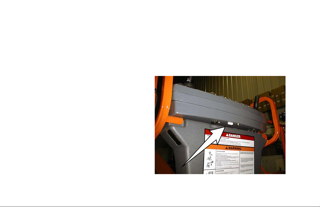
A Machine that incorporates ADE (JLG Control System) can be outwardly identified by
the analyzer connection at the base of the
platform control box as shown by the arrow.
ADE Identification
All 600S, 600SJ, and 660SJ machines from S/N 61927 incorporate ADE (JLG Control System). The following machine serial numbers prior to S/N 61927 also utilize ADE: 58993, 58998, 59222, 59223, 59275,
59281, 59315, 59319, 59352, 59358, 59631, 59769, 60253, 60254, 60286, 60642, 60645, 61120, 61257,
61402, 61440, 61491, 61833, 61840, 61875, and 61878.

FOREWORD
FOREWORD
This manual is a very important tool! Keep it with the machine at all times.
The purpose of this manual is to provide owners, users, operators, lessors, and lessees with the precautions and
operating procedures essential for the safe and proper machine operation for its intended purpose.
Due to continuous product improvements, JLG Industries, Inc. reserves the right to make specification changes
without prior notification. Contact JLG Industries, Inc. for updated information.
3121205 – JLG Lift – a
FOREWORD
SAFETY ALERT SYMBOLS AND SAFETY SIGNAL WORDS
This is the Safety Alert Symbol. It is used to alert you to the potential personal
injury hazards. Obey all safety messages that follow this symbol to avoid possible
injury or death
INDICATES AN IMMINENTLY HAZARDOUS SITUATION. IF NOT
AVOIDED, WILL RESULT IN SERIOUS INJURY OR DEATH. THIS DECAL
WILL HAVE A RED BACKGROUND.
INDICATES A POTENTIALLY HAZARDOUS SITUATION. IF NOT
AVOIDED, COULD
DECAL WILL HAVE AN ORANGE BACKGROUND.
RESULT IN SERIOUS INJURY OR DEATH. THIS
INDICATES A POTENTIALLY HAZARDOUS SITUATION. IF NOT
AVOIDED, MAY RESULT IN MINOR OR MODERATE INJURY. IT MAY
ALSO ALERT AGAINST UNSAFE PRACTICES. THIS DECAL WILL HAVE A
YELLOW BACKGROUND.
INDICATES INFORMATION OR A COMPANY POLICY THAT RELATES
DIRECTLY OR INDIRECTLY TO THE SAFETY OF PERSONNEL OR PROTECTION OF PROPERTY.
b – JLG Lift – 3121205

THIS PRODUCT MUST COMPLY WITH ALL SAFETY RELATED BULLETINS. CONTACT JLG INDUSTRIES, INC. OR THE LOCAL AUTHORIZED
JLG REPRESENTATIVE FOR INFORMATION REGARDING SAFETYRELATED BULLETINS WHICH MAY HAVE BEEN ISSUED FOR THIS
PRODUCT.
For:
• Accident Reporting
• Product Safety Publications
• Current Owner Updates
• Questions Regarding
Product Safety
FOREWORD
• Standards and Regulations
Compliance Information
• Questions Regarding Special Product Applications
• Questions Regarding Product Modifications
JLG INDUSTRIES, INC. SENDS SAFETY RELATED BULLETINS TO THE
OWNER OF RECORD OF THIS MACHINE. CONTACT JLG INDUSTRIES,
INC. TO ENSURE THAT THE CURRENT OWNER RECORDS ARE
UPDATED AND ACCURATE.
JLG INDUSTRIES, INC. MUST BE NOTIFIED IMMEDIATELY IN ALL
INSTANCES WHERE JLG PRODUCTS HAVE BEEN INVOLVED IN AN
ACCIDENT INVOLVING BODILY INJURY OR DEATH OF PERSONNEL OR
WHEN SUBSTANTIAL DAMAGE HAS OCCURRED TO PERSONAL PROPERTY OR THE JLG PRODUCT.
Contact:
Product Safety and Reliability Department
JLG Industries, Inc.
13224 Fountainhead Plaza
Hagerstown, MD 21742
USA
or Your Local JLG Office
(See addresses on inside of manual cover)
In USA:
Toll Free: 877-JLG-SAFE (877-554-7233)
Outside USA:
3121205 – JLG Lift – c
Phone: 240-420-2661
Fax: 301-745-3713
E-mail: ProductSafety@JLG.com

FOREWORD
REVISION LOG
Original Issue - April 1, 2005
Revised - February 27, 2006
Revised - May 3, 2006
Revised - September 25, 2007
Revised - February 22, 2008
Revised - June 5, 2008
Revised - September 21, 2009
Revised - December 1, 2009
Revised - October 31, 2011
Revised - May 1, 2012
d – JLG Lift – 3121205

TABLE OF CONTENTS
SECTION - PARAGRAPH, SUBJECT PAGE SECTION - PARAGRAPH, SUBJECT PAGE
SECTION - 1 - SAFETY PRECAUTIONS
1.1 GENERAL . . . . . . . . . . . . . . . . . . . . . . . . . . . . . . . . .1-1
1.2 PRE-OPERATION . . . . . . . . . . . . . . . . . . . . . . . . . . .1-1
Operator Training and Knowledge. . . . . . . . . . . 1-1
Workplace Inspection. . . . . . . . . . . . . . . . . . . . . 1-2
Machine Inspection . . . . . . . . . . . . . . . . . . . . . . 1-2
1.3 OPERATION . . . . . . . . . . . . . . . . . . . . . . . . . . . . . . .1-3
General . . . . . . . . . . . . . . . . . . . . . . . . . . . . . . . . 1-3
Trip and Fall Hazards . . . . . . . . . . . . . . . . . . . . . 1-3
Electrocution Hazards . . . . . . . . . . . . . . . . . . . . 1-4
Tipping Hazards . . . . . . . . . . . . . . . . . . . . . . . . . 1-6
Crushing and Collision Hazards. . . . . . . . . . . . . 1-7
1.4 TOWING, LIFTING, AND HAULING . . . . . . . . . . . . .1-8
1.5 ADDITIONAL HAZARDS / SAFETY . . . . . . . . . . . . .1-9
SECTION - 2 - USER RESPONSIBILITIES, MACHINE PREPARATION, AND INSPECTION
2.1 PERSONNEL TRAINING . . . . . . . . . . . . . . . . . . . . .2-1
Operator Training . . . . . . . . . . . . . . . . . . . . . . . . 2-1
Training Supervision. . . . . . . . . . . . . . . . . . . . . . 2-1
Operator Responsibility . . . . . . . . . . . . . . . . . . . 2-1
2.2 PREPARATION, INSPECTION, AND
MAINTENANCE . . . . . . . . . . . . . . . . . . . . . . . . . . .2-2
Pre-Start Inspection . . . . . . . . . . . . . . . . . . . . . . 2-4
Function Check. . . . . . . . . . . . . . . . . . . . . . . . . . 2-5
2.3 LIMIT SWITCH FUNCTIONAL CHECK . . . . . . . . . . 2-5
General . . . . . . . . . . . . . . . . . . . . . . . . . . . . . . . 2-11
SECTION - 3 - MACHINE CONTROLS AND INDICATORS
3.1 GENERAL . . . . . . . . . . . . . . . . . . . . . . . . . . . . . . . . 3-1
3.2 CONTROLS AND INDICATORS . . . . . . . . . . . . . . . 3-1
Ground Control Station . . . . . . . . . . . . . . . . . . . . 3-1
Ground Control Indicator Panel . . . . . . . . . . . . . 3-5
Platform Station . . . . . . . . . . . . . . . . . . . . . . . . . . 3-7
Platform Control Indicator Panel . . . . . . . . . . . . 3-14
SECTION - 4 - MACHINE OPERATION
4.1 DESCRIPTION. . . . . . . . . . . . . . . . . . . . . . . . . . . . . 4-1
4.2 OPERATING CHARACTERISTICS AND
LIMITATIONS . . . . . . . . . . . . . . . . . . . . . . . . . . . . 4-1
Capacities . . . . . . . . . . . . . . . . . . . . . . . . . . . . . . 4-1
Stability . . . . . . . . . . . . . . . . . . . . . . . . . . . . . . . . 4-2
4.3 ENGINE OPERATION . . . . . . . . . . . . . . . . . . . . . . . 4-2
Starting Procedure . . . . . . . . . . . . . . . . . . . . . . . 4-2
Shutdown Procedure . . . . . . . . . . . . . . . . . . . . . 4-3
4.4 TRAVELING (DRIVING) . . . . . . . . . . . . . . . . . . . . . . 4-5
Traveling Forward and Reverse . . . . . . . . . . . . . 4-5
4.5 STEERING. . . . . . . . . . . . . . . . . . . . . . . . . . . . . . . . 4-7
4.6 PLATFORM . . . . . . . . . . . . . . . . . . . . . . . . . . . . . . . 4-7
Platform Level Adjustment . . . . . . . . . . . . . . . . . 4-7
3121205 – JLG Lift – i

TABLE OF CONTENTS
SECTION - PARAGRAPH, SUBJECT PAGE SECTION - PARAGRAPH, SUBJECT PAGE
Platform Rotation . . . . . . . . . . . . . . . . . . . . . . . . 4-7
4.7 BOOM . . . . . . . . . . . . . . . . . . . . . . . . . . . . . . . . . . . 4-7
Swinging the Boom . . . . . . . . . . . . . . . . . . . . . . 4-8
Raising and Lowering the Boom . . . . . . . . . . . . 4-8
Telescoping the Boom. . . . . . . . . . . . . . . . . . . . 4-8
4.8 SHUT DOWN AND PARK . . . . . . . . . . . . . . . . . . . . 4-8
4.9 OSCILLATING AXLE LOCKOUT TEST
(IF EQUIPPED) . . . . . . . . . . . . . . . . . . . . . . . . . . . 4-9
4.10 STEER/TOW SELECTOR (IF EQUIPPED). . . . . . . . 4-9
4.11 TOWING (IF EQUIPPED). . . . . . . . . . . . . . . . . . . . . 4-9
4.12 AUXILIARY POWER - NON ADE EQUIPPED MA-
CHINES . . . . . . . . . . . . . . . . . . . . . . . . . . . . . . . . 4-13
Activating from the Platform Control Station . . 4-13
Activating from the Ground Control Station . . 4-13
4.13 AUXILIARY POWER - ADE EQUIPPED
MACHINES . . . . . . . . . . . . . . . . . . . . . . . . . . . . . 4-14
Activating from the Platform Control Station . . 4-14
Activating from the Ground Control Station . . 4-14
4.14 DUAL FUEL SYSTEM (GAS ENGINE ONLY) . . . . 4-15
Changing From Gasoline to LP Gas . . . . . . . . 4-15
Changing From LP Gas to Gasoline . . . . . . . . 4-15
4.15 HYDRAULIC TOOL CIRCUIT INSTRUCTIONS . . . 4-15
Tool Circuit . . . . . . . . . . . . . . . . . . . . . . . . . . . . 4-15
4.16 TIE DOWN AND LIFTING . . . . . . . . . . . . . . . . . . . .4-17
SECTION - 5 - EMERGENCY PROCEDURES
5.1 GENERAL . . . . . . . . . . . . . . . . . . . . . . . . . . . . . . . . .5-1
5.2 INCIDENT NOTIFICATION . . . . . . . . . . . . . . . . . . . .5-1
5.3 EMERGENCY OPERATION . . . . . . . . . . . . . . . . . . .5-1
Operator Unable to Control Machine . . . . . . . . . 5-1
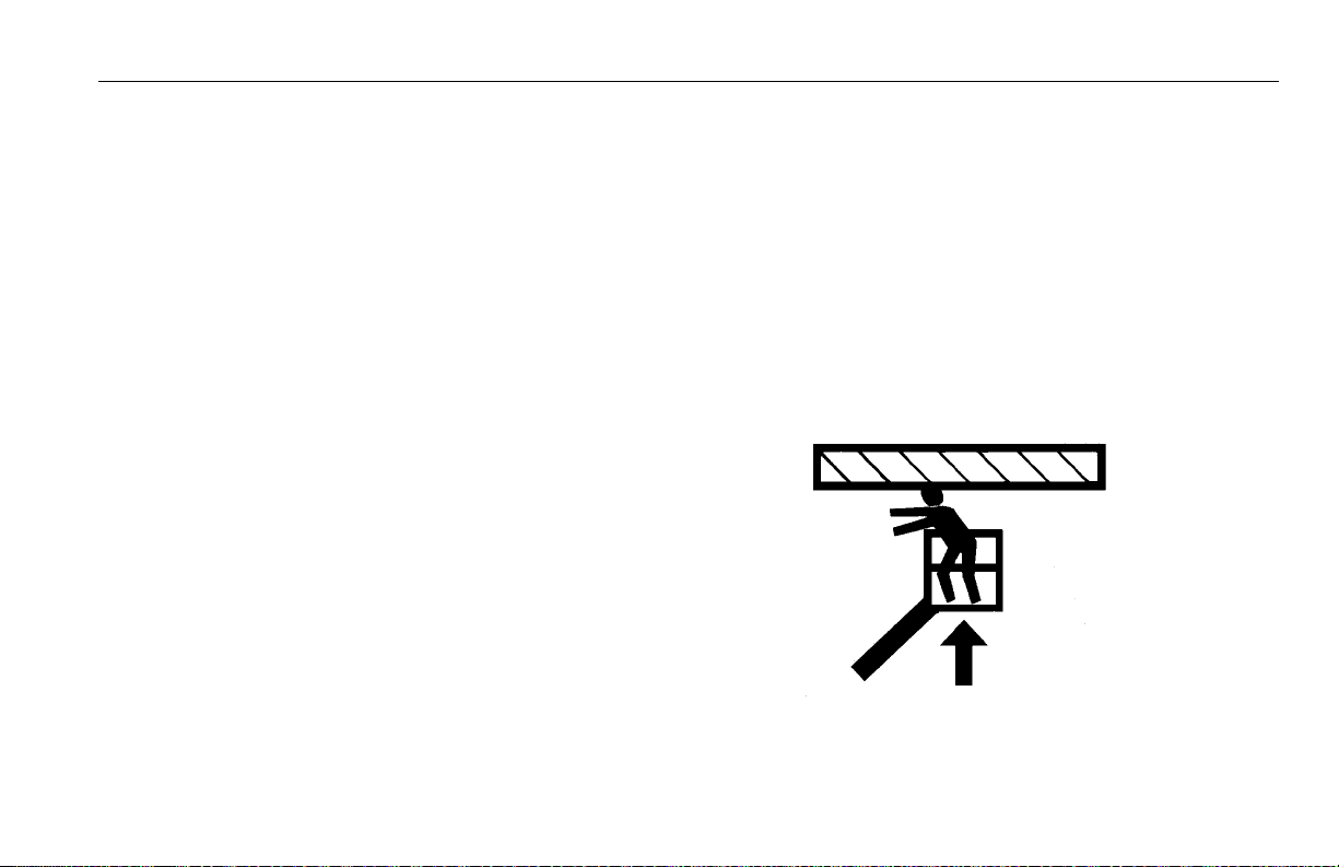
Platform or Boom Caught Overhead . . . . . . . . . 5-2
5.4 EMERGENCY TOWING PROCEDURES . . . . . . . . .5-2
5.5 MANUAL DESCENT (MACHINES PRIOR TO S/N
70975). . . . . . . . . . . . . . . . . . . . . . . . . . . . . . . . . . .5-2
SECTION - 6 - GENERAL SPECIFICATIONS & OPERATOR
MAINTENANCE
6.1 INTRODUCTION. . . . . . . . . . . . . . . . . . . . . . . . . . . .6-1
6.2 OPERATING SPECIFICATIONS. . . . . . . . . . . . . . . .6-2
Capacities . . . . . . . . . . . . . . . . . . . . . . . . . . . . . . 6-4
Engine Data . . . . . . . . . . . . . . . . . . . . . . . . . . . . 6-4
Dimensional Data . . . . . . . . . . . . . . . . . . . . . . . . 6-7
Torque Requirements. . . . . . . . . . . . . . . . . . . . . 6-7
Tires . . . . . . . . . . . . . . . . . . . . . . . . . . . . . . . . . . 6-8
Hydraulic Oil . . . . . . . . . . . . . . . . . . . . . . . . . . . . 6-8
Critical Stability Weights . . . . . . . . . . . . . . . . . . 6-10
Serial Number Locations . . . . . . . . . . . . . . . . . 6-12
ii – JLG Lift – 3121205

TABLE OF CONTENTS
SECTION - PARAGRAPH, SUBJECT PAGE SECTION - PARAGRAPH, SUBJECT PAGE
6.3 OPERATOR MAINTENANCE . . . . . . . . . . . . . . . . .6-23
6.4 TIRES & WHEELS . . . . . . . . . . . . . . . . . . . . . . . . .6-33
Tire Inflation . . . . . . . . . . . . . . . . . . . . . . . . . . . 6-33
Tire Damage . . . . . . . . . . . . . . . . . . . . . . . . . . . 6-33
Tire Replacement . . . . . . . . . . . . . . . . . . . . . . . 6-33
Wheel Replacement . . . . . . . . . . . . . . . . . . . . . 6-34
Wheel Installation . . . . . . . . . . . . . . . . . . . . . . . 6-34
6.5 OSCILLATING AXLE LOCKOUT TEST
(IF EQUIPPED) . . . . . . . . . . . . . . . . . . . . . . . . . . .6-36
6.6 DRAINING OIL BUILD UP FROM THE PROPANE REG-
ULATOR (PRIOR TO S/N 0300132529) . . . . . . . .6-38
6.7 PROPANE FUEL FILTER REPLACEMENT. . . . . . .6-39
Removal . . . . . . . . . . . . . . . . . . . . . . . . . . . . . . 6-39
Installation. . . . . . . . . . . . . . . . . . . . . . . . . . . . . 6-41
6.8 PROPANE FUEL SYSTEM PRESSURE RELIEF . .6-41
6.9 SUPPLEMENTAL INFORMATION . . . . . . . . . . . . .6-42
SECTION - 7 - INSPECTION AND REPAIR LOG
LIST OF FIGURES
2-1. Machine Nomenclature - 600SJ/660SJ . . . . . . . . . 2-8
2-2. Machine Nomenclature - 600S . . . . . . . . . . . . . . . . 2-9
2-3. Daily Walk-Around Inspection Diagram . . . . . . . . 2-10
2-4. Daily Walk-Around Inspection Points -
Sheet 1 of 3 . . . . . . . . . . . . . . . . . . . . . . . . . . . . . 2-11
2-5. Daily Walk-Around Inspection Points -
Sheet 2 of 3 . . . . . . . . . . . . . . . . . . . . . . . . . . . . . 2-12
2-6. Daily Walk-Around Inspection Points -
Sheet 3 of 3 . . . . . . . . . . . . . . . . . . . . . . . . . . . . . 2-13
3-1. Ground Control Station. . . . . . . . . . . . . . . . . . . . . . 3-2
3-2. Ground Control Indicator Panel . . . . . . . . . . . . . . . 3-5
3-3. Malfunction Indicator Light and Test Button . . . . . 3-7
3-4. Platform Control Console . . . . . . . . . . . . . . . . . . . . 3-8
3-5. Platform Control Console - w/Drive Orientation . . . 3-9
3-6. Platform Control Indicator Panel . . . . . . . . . . . . . 3-15
3-7. Platform Control Indicator Panel -
w/Drive Orientation . . . . . . . . . . . . . . . . . . . . . . . 3-16
4-1. Position of Least Backward Stability . . . . . . . . . . . 4-3
4-2. Position of Least Forward Stability . . . . . . . . . . . . . 4-4
4-3. Grade and Sideslope . . . . . . . . . . . . . . . . . . . . . . . 4-6
4-4. Drive Disconnect Hub. . . . . . . . . . . . . . . . . . . . . . 4-10
4-5. Towbar Connecting Points - Prior to S/N 75606 . 4-11
4-6. Towbar Connecting Points - S/N 75606
to Present . . . . . . . . . . . . . . . . . . . . . . . . . . . . . . 4-12
3121205 – JLG Lift – iii

TABLE OF CONTENTS
SECTION - PARAGRAPH, SUBJECT PAGE SECTION - PARAGRAPH, SUBJECT PAGE
4-7. Machine Tie Down. . . . . . . . . . . . . . . . . . . . . . . . . 4-18
4-8. Lifting Chart . . . . . . . . . . . . . . . . . . . . . . . . . . . . . . 4-19
4-9. Decal Installation - Sheet 1 of 4. . . . . . . . . . . . . . . 4-20
4-10. Decal Installation - Sheet 2 of 4. . . . . . . . . . . . . . . 4-21
4-11. Decal Installation - Sheet 3 of 4. . . . . . . . . . . . . . . 4-22
4-12. Decal Installation - Sheet 4 of 4. . . . . . . . . . . . . . . 4-23
6-1. Serial Number Locations. . . . . . . . . . . . . . . . . . . . 6-12
6-2. Engine Operating Temperature Specifications - Deutz
- Sheet 1 of 2 . . . . . . . . . . . . . . . . . . . . . . . . . . . . 6-14
6-3. Engine Operating Temperature Specifications - Deutz
- Sheet 2 of 2 . . . . . . . . . . . . . . . . . . . . . . . . . . . . 6-15
6-4. Engine Operating Temperature Specifications - Ford -
Sheet 1 of 2 . . . . . . . . . . . . . . . . . . . . . . . . . . . . . 6-16
6-5. Engine Operating Temperature Specifications - Ford -
Sheet 2 of 2 . . . . . . . . . . . . . . . . . . . . . . . . . . . . . 6-17
6-6. Engine Operating Temperature Specifications -
Caterpillar - Sheet 1 of 2 . . . . . . . . . . . . . . . . . . . 6-18
6-7. Engine Operating Temperature Specifications -
Caterpillar - Sheet 2 of 2 . . . . . . . . . . . . . . . . . . . 6-19
6-8. Engine Operating Temperature Specifications - GM -
Sheet 1 of 2 . . . . . . . . . . . . . . . . . . . . . . . . . . . . . 6-20
6-9. Engine Operating Temperature Specifications - GM -
Sheet 2 of 2 . . . . . . . . . . . . . . . . . . . . . . . . . . . . . 6-21
6-10. Operator Maintenance & Lubrication Diagram . . . 6-22
6-11. Filter Lock Assembly . . . . . . . . . . . . . . . . . . . . . . . 6-40
LIST OF TABLES
1-1 Minimum Approach Distances (M.A.D.). . . . . . . . . 1-5
1-2 Beaufort Scale (For Reference Only) . . . . . . . . . . 1-10
2-1 Inspection and Maintenance Table . . . . . . . . . . . . 2-3
4-1 600S Decal Legend - Prior to S/N XXXXXX . . . . . 4-24
4-2 600S Decal Legend - S/N XXXXXX to Present. . . 4-28
4-3 600SJ Decal Legend . . . . . . . . . . . . . . . . . . . . . . 4-32
4-4 660SJ Decal Legend - Prior to S/N XXXXXX . . . . 4-36
4-5 660SJ Decal Legend - S/N XXXXXX to Present . . 4-40
6-1 Operating Specifications - Prior to S/N XXXXXX . . 6-2
6-2 Operating Specifications - S/N XXXXXX to Present 6-3
6-3 Capacities. . . . . . . . . . . . . . . . . . . . . . . . . . . . . . . . 6-4
6-4 Ford LRG-425 Specifications . . . . . . . . . . . . . . . . . 6-4
6-5 Deutz F4M1011F/F4M2011 Specifications . . . . . . 6-5
6-6 Deutz D2011L04 Specifications . . . . . . . . . . . . . . . 6-5
6-7 Caterpillar 3044C / 3.4 . . . . . . . . . . . . . . . . . . . . . . 6-6
6-8 GM 3.0L . . . . . . . . . . . . . . . . . . . . . . . . . . . . . . . . . 6-6
6-9 Dimensional Data . . . . . . . . . . . . . . . . . . . . . . . . . . 6-7
6-10 Torque Requirements. . . . . . . . . . . . . . . . . . . . . . . 6-7
6-11 Tire Specifications . . . . . . . . . . . . . . . . . . . . . . . . . 6-8
6-12 Hydraulic Oil . . . . . . . . . . . . . . . . . . . . . . . . . . . . . . 6-8
6-13 Mobilfluid 424 Specs . . . . . . . . . . . . . . . . . . . . . . . 6-8
6-14 Mobil DTE 13M Specs . . . . . . . . . . . . . . . . . . . . . . 6-9
6-15 Exxon Univis HVI 26 Specs . . . . . . . . . . . . . . . . . . 6-9
6-16 Quintolubric 888-46 . . . . . . . . . . . . . . . . . . . . . . . 6-10
iv – JLG Lift – 3121205

TABLE OF CONTENTS
SECTION - PARAGRAPH, SUBJECT PAGE SECTION - PARAGRAPH, SUBJECT PAGE
6-17 Critical Stability Weights - 600S . . . . . . . . . . . . . . 6-10
6-18 Critical Stability Weights - 600SJ . . . . . . . . . . . . . 6-11
6-19 Critical Stability Weights - 660SJ . . . . . . . . . . . . . 6-11
6-20 Lubrication Specifications . . . . . . . . . . . . . . . . . . 6-23
6-22 Wheel Torque Chart - 10 Lug. . . . . . . . . . . . . . . . 6-36
6-21 Wheel Torque Chart - 9 Lug. . . . . . . . . . . . . . . . . 6-36
7-1 Inspection and Repair Log . . . . . . . . . . . . . . . . . . . 7-1
3121205 – JLG Lift – v

TABLE OF CONTENTS
SECTION - PARAGRAPH, SUBJECT PAGE SECTION - PARAGRAPH, SUBJECT PAGE
This page left blank intentionally.
vi – JLG Lift – 3121205
SECTION 1 - SAFETY PRECAUTIONS
SECTION 1. SAFETY PRECAUTIONS
1.1 GENERAL
This section outlines the necessary precautions for proper
and safe machine operation and maintenance. For proper
machine use, it is mandatory that a daily routine is established based on the content of this manual. A maintenance
program, using the information provided in this manual and
the Service and Maintenance Manual, must also be established by a qualified person and followed to ensure the
machine is safe to operate.
The owner/user/operator/lessor/lessee of the machine
should not operate the machine until this manual has been
read, training is accomplished, and operation of the machine
has been completed under the supervision of an experienced and qualified operator.
If there are any questions with regard to safety, training,
inspection, maintenance, application, and operation, please
contact JLG Industries, Inc. (“JLG”).
FAILURE TO COMPLY WITH THE SAFETY PRECAUTIONS LISTED IN
THIS MANUAL COULD RESULT IN MACHINE DAMAGE, PROPERTY DAMAGE, PERSONAL INJURY OR DEATH.
1.2 PRE-OPERATION
Operator Training and Knowledge
• Read and understand this manual before operating the
machine.
• Do not operate this machine until complete training is performed by authorized persons.
• Only authorized and qualified personnel can operate the
machine.
3121205 – JLG Lift – 1-1

SECTION 1 - SAFETY PRECAUTIONS
• Read, understand, and obey all DANGERS, WARNINGS,
CAUTIONS, and operating instructions on the machine
and in this manual.
• Use the machine in a manner which is within the scope of
its intended application set by JLG.
• All operating personnel must be familiar with the emergency controls and emergency operation of the machine
as specified in this manual.
• Read, understand, and obey all applicable employer,
local, and governmental regulations as they pertain to
operation of the machine.
Workplace Inspection
• The operator is to take safety measures to avoid all hazards in the work area prior to machine operation.
• Do not operate or raise the platform while on trucks, trailers, railway cars, floating vessels, scaffolds or other equipment unless approved in writing by JLG.
• Do not operate the machine in hazardous environments
unless approved for that purpose by JLG.
• Be sure that the ground conditions are able to support the
maximum load shown on the decals located on the
machine.
Machine Inspection
• Before machine operation, perform inspections and functional checks. Refer to Section 2 of this manual for
detailed instructions.
• Do not operate this machine until it has been serviced and
maintained according to requirements specified in the
Service and Maintenance Manual.
• Be sure the footswitch and all other safety devices are
operating properly. Modification of these devices is a
safety violation.
MODIFICATION OR ALTERATION OF AN AERIAL WORK PLATFORM
SHALL BE MADE ONLY WITH WRITTEN PERMISSION FROM THE MANUFACTURER
• Do not operate any machine on which safety or instruction
placards or decals are missing or illegible.
• Avoid any buildup of debris on the platform floor. Keep
mud, oil, grease, and other slippery substances from footwear and platform floor.
1-2 – JLG Lift – 3121205
SECTION 1 - SAFETY PRECAUTIONS
1.3 OPERATION
General
• Do not use the machine for any purpose other than positioning personnel, their tools, and equipment.
• Never operate a machine that is not working properly. If a
malfunctions occurs, shut down the machine.
• Never slam a control switch or lever through neutral to an
opposite direction. Always return switch to neutral and
stop before moving the switch to the next function. Operate controls with slow and even pressure.
• Do not allow personnel to tamper with or operate the
machine from the ground with personnel in the platform,
except in an emergency.
• Do not carry materials directly on platform railing. Contact
JLG for approved material handling accessories.
• When two or more persons are in the platform, the operator shall be responsible for all machine operations.
• Always ensure that power tools are properly stowed and
never left hanging by their cord from the platform work
area.
• Supplies or tools which extend outside the platform are
prohibited unless approved by JLG.
• When driving, always position boom over rear axle in line
with the direction of travel. Remember, if boom is over the
front axle, steer and drive functions will be reversed.
• Do not assist a stuck or disabled machine by pushing,
pulling, or by using boom functions. Only pull the unit
from the tie-down lugs on the chassis.
• Do not place boom or platform against any structure to
steady the platform or to support the structure.
• Stow boom and shut off all power before leaving machine.
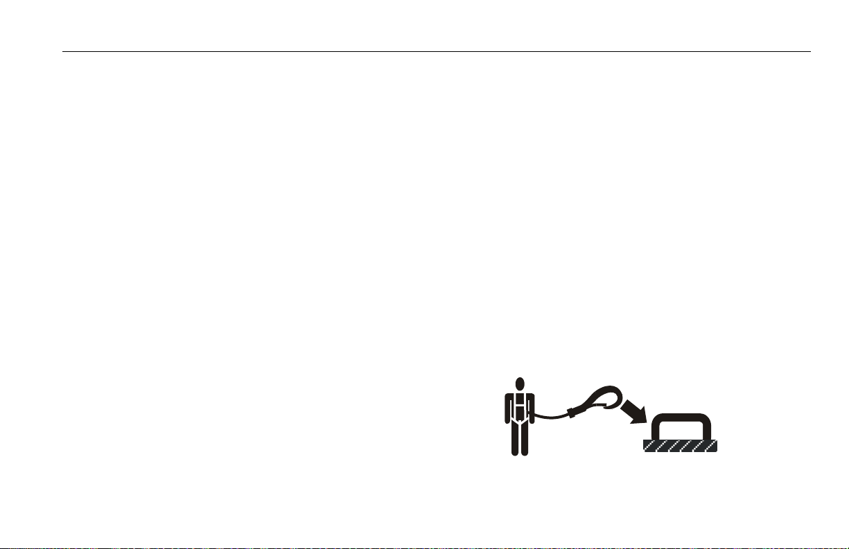
Trip and Fall Hazards
During operation, occupants in the platform must wear a full
body harness with a lanyard attached to an authorized lanyard anchorage point. Attach only one (1) lanyard per lanyard anchorage point.
3121205 – JLG Lift – 1-3
SECTION 1 - SAFETY PRECAUTIONS
• Before operating the machine, make sure all gates are
closed and fastened in their proper position.
• Keep both feet firmly positioned on the platform floor at all
times. Never use ladders, boxes, steps, planks, or similar
items on platform to provide additional reach.
• Never use the boom assembly to enter or leave the platform.
• Use extreme caution when entering or leaving platform.
Be sure that the boom is fully lowered. It may be necessary to telescope out to position the platform closer to the
ground for entry/exit. Face the machine, maintain “three
point contact” with the machine, using two hands and one
foot or two feet and one hand during entry and exit.
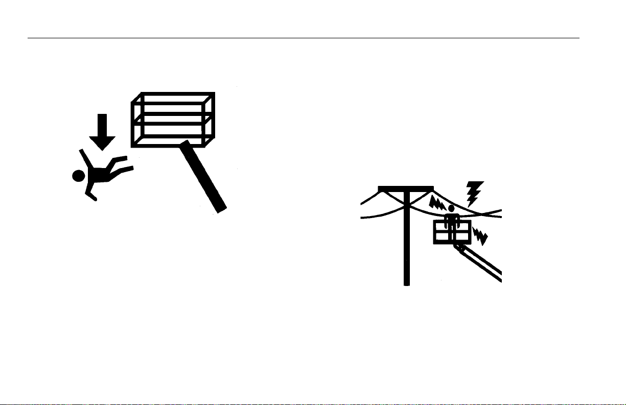
Electrocution Hazards
• This machine is not insulated and does not provide protection from contact or proximity to electrical current.
1-4 – JLG Lift – 3121205
SECTION 1 - SAFETY PRECAUTIONS
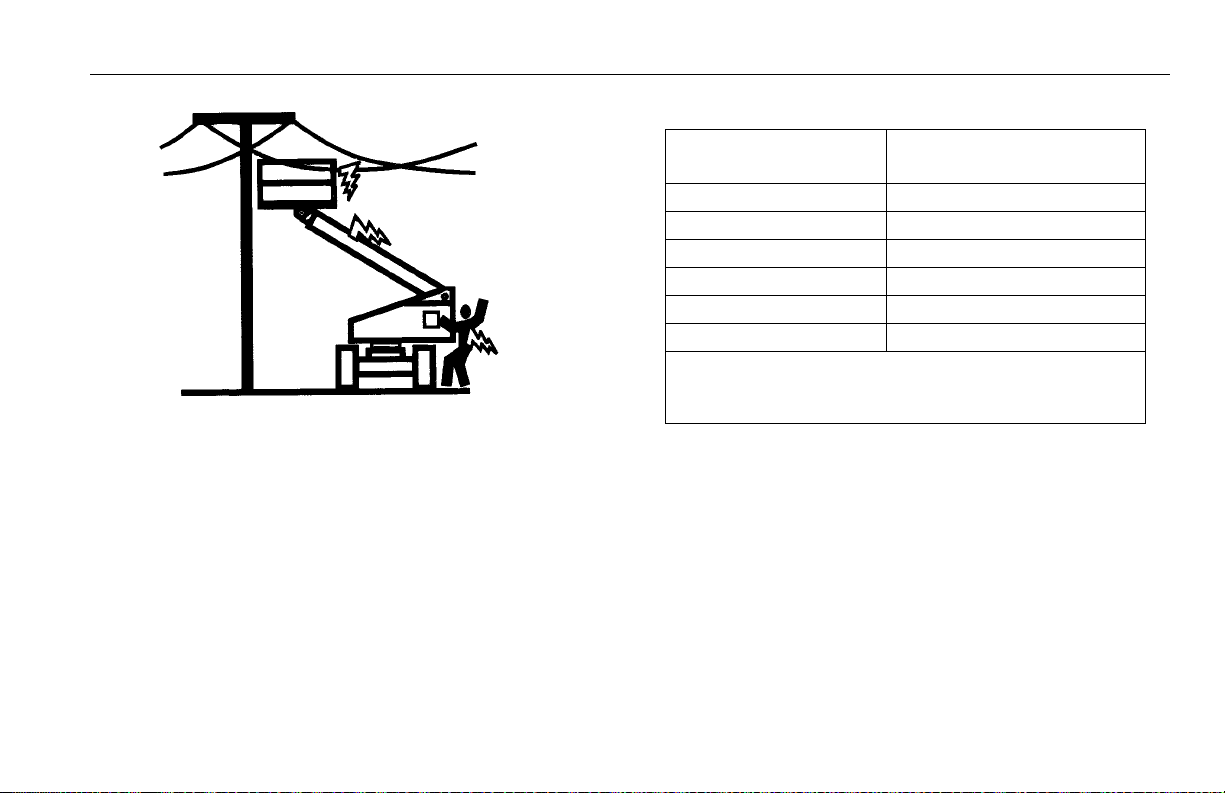
Table 1-1. Minimum Approach Distances (M.A.D.)
• Maintain distance from electrical lines, apparatus, or any
energized (exposed or insulated) parts according to the
Minimum Approach Distance (MAD) as shown in Table 1-
1.
• Allow for machine movement and electrical line swaying.
Voltage Range
(Phase to Phase)
0 to 50 KV 10 (3)
Over 50KV to 200 KV 15 (5)
Over 200 KV to 350 KV 20 (6)
Over 350 KV to 500 KV 25 (8)
Over 500 KV to 750 KV 35 (11)
Over 750 KV to 1000 KV 45 (14)
NOTE: This requirement shall apply except where
employer, local or governmental regulations
are more stringent.
• Maintain a clearance of at least 10 ft. (3m) between any part
of the machine and its occupants, their tools, and their
equipment from any electrical line or apparatus carrying up
to 50,000 volts. One foot additional clearance is required for
every additional 30,000 volts or less.
MINIMUM APPROACH DISTANCE
in Feet (Meters)
3121205 – JLG Lift – 1-5
SECTION 1 - SAFETY PRECAUTIONS
• The minimum approach distance may be reduced if insulating barriers are installed to prevent contact, and the barriers
are rated for the voltage of the line being guarded. These
barriers shall not be part of (or attached to) the machine. The
minimum approach distance shall be reduced to a distance
within the designed working dimensions of the insulating
barrier. This determination shall be made by a qualified person in accordance with the employer, local, or governmental
requirements for work practices near energized equipment
DO NOT MANEUVER MACHINE OR PERSONNEL INSIDE PROHIBITED
ZONE (MAD). ASSUME ALL ELECTRICAL PARTS AND WIRING ARE
ENERGIZED UNLESS KNOWN OTHERWISE.
Tipping Hazards
• The user must be familiar with the surface before driving.
Do not exceed the allowable sideslope and grade while
driving.
1-6 – JLG Lift – 3121205
SECTION 1 - SAFETY PRECAUTIONS
• Do not elevate platform or drive with platform elevated
while on a sloping, uneven, or soft surface.
• Before driving on floors, bridges, trucks, and other surfaces, check allowable capacity of the surfaces.
• Never exceed the maximum platform capacity. Distribute
loads evenly on platform floor.
• Do not raise the platform or drive from an elevated position unless the machine is on firm, level and smooth surfaces.
• Keep the chassis of the machine at least 2 ft. (0.6m) from
holes, bumps, drop-offs, obstructions, debris, concealed
holes, and other potential hazards on the floor/surface.
• Do not push or pull any object with the boom.
• Never attempt to use the machine as a crane. Do not tieoff machine to any adjacent structure.
• Do not operate the machine when wind conditions exceed
28 mph (12.5 m/s). Refer to Table 1-2, Beaufort Scale (For
Reference Only).
• Do not increase the surface area of the platform or the
load. Increase of the area exposed to the wind will
decrease stability.
• Do not increase the platform size with unauthorized deck
extensions or attachments.
• If boom assembly or platform is in a position that one or
more wheels are off the ground, all persons must be
removed before attempting to stabilize the machine. Use
cranes, forklift trucks, or other appropriate equipment to
stabilize machine.
Crushing and Collision Hazards
• Approved head gear must be worn by all operating and
ground personnel.
• Check work area for clearances overhead, on sides, and
bottom of platform when lifting or lowering platform, and
driving.
• During operation, keep all body parts inside platform railing.
3121205 – JLG Lift – 1-7

SECTION 1 - SAFETY PRECAUTIONS
• Use the boom functions, not the drive function, to position
the platform close to obstacles.
• Always post a lookout when driving in areas where vision
is obstructed.
• Keep non-operating personnel at least 6 ft. (1.8m) away
from machine during all driving and swing operations.
• Limit travel speed according to conditions of ground surface, congestion, visibility, slope, location of personnel,
and other factors which may cause collision or injury to
personnel.
• Be aware of stopping distances in all drive speeds. When
driving in high speed, switch to low speed before stopping. Travel grades in low speed only.
• Do not use high speed drive in restricted or close quarters
or when driving in reverse.
• Exercise extreme caution at all times to prevent obstacles
from striking or interfering with operating controls and persons in the platform.
• Be sure that operators of other overhead and floor level
machines are aware of the aerial work platform’s presence. Disconnect power to overhead cranes.
• Warn personnel not to work, stand, or walk under a raised
boom or platform. Position barricades on floor if necessary.
1.4 TOWING, LIFTING, AND HAULING
• Never allow personnel in platform while towing, lifting, or
hauling.
• This machine should not be towed, except in the event of
emergency, malfunction, power failure, or loading/unloading. Refer to the Emergency Procedures section of this
manual for emergency towing procedures.
• Ensure boom is in the stowed position and the turntable
locked prior to towing, lifting or hauling. The platform must
be completely empty of tools.
• When lifting machine, lift only at designated areas of the
machine. Lift the unit with equipment of adequate capacity.
• Refer to the Machine Operation section of this manual for
lifting information.
1-8 – JLG Lift – 3121205

SECTION 1 - SAFETY PRECAUTIONS
1.5 ADDITIONAL HAZARDS / SAFETY
• Do not use machine as a ground for welding.
• When performing welding or metal cutting operations,
precautions must be taken to protect the chassis from
direct exposure to weld and metal cutting spatter.
• Do not refuel the machine with the engine running.
• Battery fluid is highly corrosive. Avoid contact with skin
and clothing at all times.
• Charge batteries only in a well ventilated area.
3121205 – JLG Lift – 1-9
SECTION 1 - SAFETY PRECAUTIONS
DO NOT OPERATE THE MACHINE WHEN WIND CONDITIONS EXCEED 28
MPH (12.5 M/S).
Table 1-2. Beaufort Scale (For Reference Only)
Beaufort
Number
0 0 0-0.2 Calm Calm. Smoke rises vertically
1 1-3 0.3-1.5 Light air Wind motion visible in smoke
2 4-7 1.6-3.3 Light breeze Wind felt on exposed skin. Leaves ru stle
3 8-12 3.4-5.4 Gentle breeze Leaves and smaller twigs in constant motion
4 13-18 5.5-7.9 Moderate breeze Dust and loose paper raised. Small branches begin to move.
5 19-24 8.0-10.7 Fresh breeze Smaller trees sway.
6 25-31 10.8-13.8 Strong breeze Large branches in motion. Whistling heard in overhead wires.
7 32-38 13.9-17.1 Near Gale/Moderate Gale Whole trees in motion. Effor t needed to walk against the wind.
8 39-46 17.2-20.7 Fresh Gale Twigs broken from trees. Cars veer on road.
9 47-54 20.8-24.4 Strong Gale Light structure damage.
Wind Speed
mph m/s
Description Land Conditions
Umbrella use becomes difficult.
1-10 – JLG Lift – 3121205

SECTION 2 - USER RESPONSIBILITIES, MACHINE PREPARATION, AND INSPECTION
SECTION 2. USER RESPONSIBILITIES, MACHINE PREPARATION, AND INSPECTION
2.1 PERSONNEL TRAINING
The aerial platform is a personnel handling device; so it is
necessary that it be operated and maintained only by trained
personnel.
Persons under the influence of drugs or alcohol or who are
subject to seizures, dizziness or loss of physical control must
not operate this machine.
Operator Training
Operator training must cover:
1. Use and limitations of the controls in the platform and at
the ground, emergency controls and safety systems.
2. Control labels, instructions, and warnings on the
machine.
3. Rules of the employer and government regulations.
4. Use of approved fall protection device.
5. Enough knowledge of the mechanical operation of the
machine to recognize a malfunction or potential malfunction.
6. The safest means to operate the machine where overhead obstructions, other moving equipment, and obstacles, depressions, holes, dropoffs.
7. Means to avoid the hazards of unprotected electrical
conductors.
8. Specific job requirements or machine application.
Training Supervision
Training must be done under the supervision of a qualified
person in an open area free of obstructions until the trainee
has developed the ability to safely control and operate the
machine.
Operator Responsibility
The operator must be instructed that he/she has the responsibility and authority to shut down the machine in case of a
malfunction or other unsafe condition of either the machine
or the job site.
3121205 – JLG Lift – 2-1

SECTION 2 - USER RESPONSIBILITIES, MACHINE PREPARATION, AND INSPECTION
2.2 PREPARATION, INSPECTION, AND MAINTENANCE
The following table covers the periodic machine inspections
and maintenance recommended by JLG Industries, Inc.
Consult local regulations for further requirements for aerial
work platforms. The frequency of inspections and maintenance must be increased as necessary when the machine is
used in a harsh or hostile environment, if the machine is
used with increased frequency, or if the machine is used in a
severe manner.
JLG INDUSTRIES, INC. RECOGNIZES A FACTORY-QUALIFIED SERVICE
TECHNICIAN AS A PERSON WHO HAS SUCCESSFULLY COMPLETED
THE JLG SERVICE TRAINING SCHOOL FOR THE SPECIFIC JLG PRODUCT
MODEL.
2-2 – JLG Lift – 3121205

SECTION 2 - USER RESPONSIBILITIES, MACHINE PREPARATION, AND INSPECTION
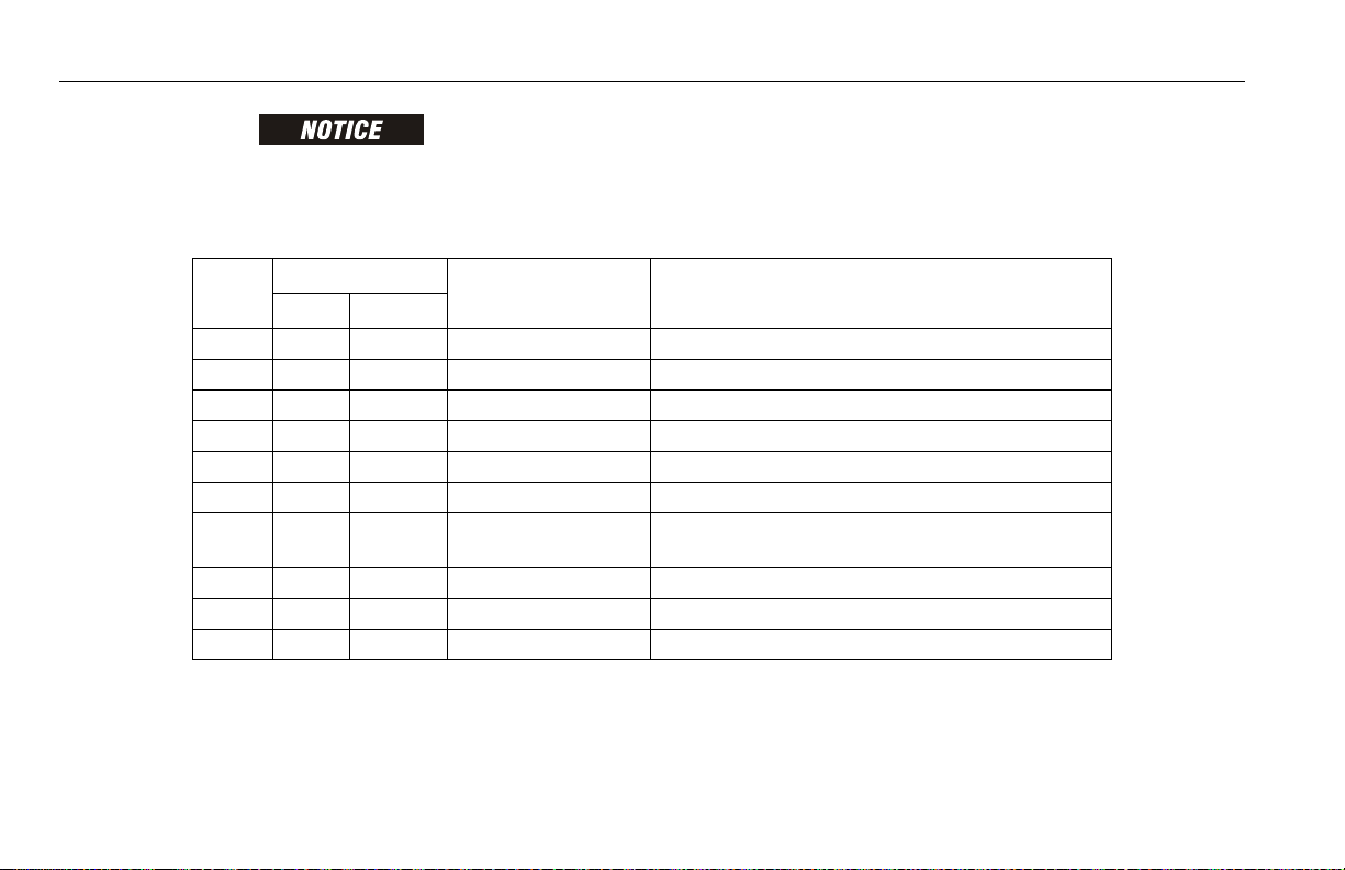
Table 2-1.Inspection and Maintenance Table
Type Frequency
Pre-Start Inspection Before using each day; or
whenever there’s an Operator change.
Pre-Delivery Inspection
(See Note)
Frequent Inspection In ser vice for 3 months or 150 hours, whichever
Annual Machine Inspection Annually, no later than 13 months from the date of
Preventative Maintenance At intervals as specified in the Ser vice and Main-
NOTE: Inspection forms are available from JLG. Use the Service and Maintenance Manual to perform inspections.
Before each sale, lease, or rental delivery. Owner, Dealer, or User Qualified JLG
comes first;
or
Out of service for a period of more than 3 months;
or
Purchased used.
prior inspection.
tenance Manual.
Primary
Responsibility
User or Operator User or Operator Operator and Safety Manual
Owner, Dealer, or User Qualified JLG
Owner, Dealer, or User Factory-Qualified
Owner, Dealer, or User Qualified JLG
Service
Qualification
Mechanic
Mechanic
Service Technician
Mechanic
Reference
Service and Maintenance
Manual and applicable JLG
inspection form
Service and Maintenance
Manual and applicable JLG
inspection form
Service and Maintenance
Manual and applicable JLG
inspection form
Service and Maintenance
Manual
3121205 – JLG Lift – 2-3
SECTION 2 - USER RESPONSIBILITIES, MACHINE PREPARATION, AND INSPECTION
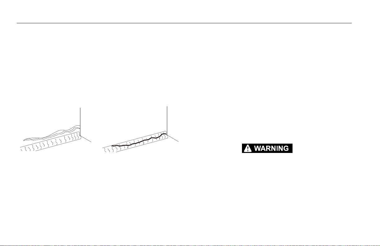
Pare nt Metal C rack Weld Crack
Pre-Start Inspection
The Pre-Start Inspection should include each of the following:
1. Cleanliness – Check all surfaces for leakage (oil, fuel,
or battery fluid) or foreign objects. Report any leakage to
the proper maintenance personnel.
2. Structure - Inspect the machine structure for dents,
damage, weld or parent metal cracks or other discrepancies.
3. Decals and Placards – Check all for cleanliness and
legibility. Make sure none of the decals and placards are
missing. Make sure all illegible decals and placards are
cleaned or replaced.
4. Operators and Safety Manuals – Make sure a copy of
the Operator and Safety Manual, EMI Safety Manual
(Domestic only), and ANSI Manual of Responsibilities
(Domestic only) is enclosed in the weather resistant
storage container.
5. “Walk-Around” Inspection – Refer to Figure 2-3. thru
Figure 2-6.
6. Battery – Charge as required.
7. Fuel (Combustion Engine Powered Machines) – Add the
proper fuel as necessary.
8. Hydraulic Oil – Check the hydraulic oil level. Ensure
hydraulic oil is added as required.
9. Function Check – Once the “Walk-Around” Inspection
is complete, perform a functional check of all systems in
an area free of overhead and ground level obstructions.
Refer to Section 4 for more specific instructions.
IF THE MACHINE DOES NOT OPERATE PROPERLY, TURN OFF THE
MACHINE IMMEDIATELY! REPORT THE PROBLEM TO THE PROPER
MAINTENANCE PERSONNEL. DO NOT OPERATE THE MACHINE UNTIL IT
IS DECLARED SAFE FOR OPERATION.
2-4 – JLG Lift – 3121205

SECTION 2 - USER RESPONSIBILITIES, MACHINE PREPARATION, AND INSPECTION
Function Check
Perform the Function Check as follows:
1. From the ground control panel with no load in the platform:
a. Check that all guards protecting the switches or
locks are in place;
b. Operate all functions and check all limiting and cut-
out switches;
c. Check auxiliary power (or manual descent);
d. Ensure that all machine functions are disabled
when the Emergency Stop Button is activated.
2. From the platform control console:
a. Ensure that the control console is firmly secured in
the proper location;
b. Check that all guards protecting the switches or
locks are in place;
c. Operate all functions and check all limiting and cut-
out switches;
d. Ensure that all machine functions are disabled
when the Emergency Stop Button is pushed in.
3. With the platform in the transport (stowed) position:
a. Drive the machine on a grade, not to exceed the
rated gradeability, and stop to ensure the brakes
hold;
b. Check the tilt sensor alarm to ensure proper opera-
tion.
3121205 – JLG Lift – 2-5

SECTION 2 - USER RESPONSIBILITIES, MACHINE PREPARATION, AND INSPECTION
2.3 LIMIT SWITCH FUNCTIONAL CHECK
TO AVOID COLLISION AND INJURY IF PLATFORM DOES NOT STOP
WHEN A CONTROL SWITCH OR LEVER IS RELEASED, REMOVE FOOT
FROM FOOTSWITCH OR USE EMERGENCY STOP TO STOP THE
MACHINE.
NOTE: Perform checks from ground controls first, then from plat-
form controls.
1. Operate machine from ground control.
NOTE: For adjustments see Service Manual - Limit Switch Adjust-
ments.
2. Check elevation limit switch as follows:
a. Lift boom up to 2 degrees to 7 degrees above hori-
zontal. The switch should activate at this point.
b. Lift boom down to 2.5 degrees to 7.5 degrees
below horizontal. The switch should reset at this
point.
3. Raise main boom, extend and retract telescope. Check
for delayed movement of fly section, indicating loose
cables.
4. Swing turntable to LEFT and RIGHT a minimum of 45
degrees. Check for smooth motion.
NOTE: Step 5 is only applicable for machines with an external tilt
sensor.
5. With the aid of an assistant to monitor the CHASSIS
OUT OF LEVEL indicator light on the platform control
console, manually activate the indicator light by compressing any one of the three tilt indicator mounting
springs. If the light does not illuminate, shut down
machine and contact a qualified service technician
before continuing operation.
NOTE: Step 6 is applicable for machines with an internal tilt sen-
sor.
6. Check the chassis out of level indicator located on the
platform control console by driving, with the machine in
level position, up a suitable ramp of at least 5° slope.
Check the out of level indicator, with the machine on the
ramp. If the light does not illuminate, return the machine
to a level surface, shut down the machine, and contact a
qualified technician before resuming operation.
2-6 – JLG Lift – 3121205

SECTION 2 - USER RESPONSIBILITIES, MACHINE PREPARATION, AND INSPECTION
NOTE: Steps 7 & 8 cover 600S ANSI market machines with dual
capacities (500 & 1000 lb. [227 kg for ANSI markets and
230 kg for CE and Australia markets & 454 kg for ANSI
markets and 450 kg for CE and Australia markets]).
7. Check capacity limit switch as follows:
Boom Length Switch.
a. Raise boom to horizontal (place angle indicator on
base boom between boom pivot pin and lift cylinder
attach pin).
b. Telescope boom out until 500 lb. (227 kg for ANSI
markets and 230 kg for CE and Australia markets)
light comes on (may need to used auxiliary power
to position boom correctly).
c. Mark wear pad location on the fly and mid booms.
d. Telescope boom out to full extension.
e. Measure from the mark on the fly boom to the wear
pad and measure from mark on the mid boom to
the wear pad.
f. Add These two numbers together (they should be
approximately equal) they should measure 137" to
139" (348 to 353 cm).
Boom Angle Switch.
a. Telescope boom to full extension.
b. Lift boom up until 1000 lb. (454 kg for ANSI markets
and 450 kg for CE and Australia markets) light
comes on.
c. Lift boom down using auxiliary power until 500 lb.
(227 kg for ANSI markets and 230 kg for CE and
Australia markets) light comes on. Boom angle
must be 45 degrees to 50 degrees (place angle
indicator on base boom between boom pivot pin
and lift cylinder attach pin).
d. Lift boom up until 1000 lb. (454 kg for ANSI markets
and 450 kg for CE and Australia markets) light
comes on. Boom angle should be 55 degrees to 64
degrees.
NOTE: If limit switch settings need to be changed, you will need
to recheck that the 500 lb. (227 kg for ANSI markets and
230 kg for CE and Australia markets) light comes on at 45
degrees to 50 degrees when lifting down.
3121205 – JLG Lift – 2-7

SECTION 2 - USER RESPONSIBILITIES, MACHINE PREPARATION, AND INSPECTION
8. Check capacity limit switch as follows:
Main Boom Length Switch.
a. Lift main boom to approximately horizontal.
b. Telescope boom out until 500 lb. (227 kg for ANSI
markets and 230 kg for CE and Australia markets)
light comes on (may need to used auxiliary power
to position boom correctly).
c. Mark the wear pad location on the main fly boom.
d. Telescope the main boom to full extension.
e. Measure from the mark on the fly boom to the wear
pad. The dimension should be 125" to 127" (317.5
to 322.5 cm).
Main Boom Angle Switch.
a. Lift main boom to approximately horizontal.
b. Telescope boom out until 500 lb. (227 kg for ANSI
markets and 230 kg for CE and Australia markets)
light comes on (may need to used auxiliary power
to position boom correctly).
c. Lift main boom up until 1000 lb. (454 kg for ANSI
markets and 450 kg for CE and Australia markets)
light comes on. The boom angle at this point should
be 55 degrees to 60 degrees.
d. Lift main boom down until 500 lb. (227 kg for ANSI
markets and 230 kg for CE and Australia markets)
light comes on. The boom angle at this point should
be 45 degrees to 50 degrees.
NOTE: If limit switch settings need to be changed, you will need
to recheck that the 500 lb. (227 kg for ANSI markets and
230 kg for CE and Australia markets) light comes on at 45
degrees to 50 degrees when lifting down.
2-8 – JLG Lift – 3121205

SECTION 2 - USER RESPONSIBILITIES, MACHINE PREPARATION, AND INSPECTION
Figure 2-1. Machine Nomenclature - 600SJ/660SJ
1. Platform
2. Platform Control Box
3. Rotator
4. Articulating Jib
5. Fly Boom
6. Mid Boom
7. Base Boom
8. Boom Assembly
9. Telescope Cylinder
( I ns i de )
10. Ground Control Box
11. Turntable
12. Steer Wheels
13. Frame
14. Drive Wheels
15. Swing Bearing
16. Lift Cylinder
17. Slave Level Cylinder
18. Ar ticulating Jib
L i ft C y li n de r
19. Footswitch
3121205 – JLG Lift – 2-9

SECTION 2 - USER RESPONSIBILITIES, MACHINE PREPARATION, AND INSPECTION
Figure 2-2. Machine Nomenclature - 600S
1. Platform
2. Platform Control Box
3. Rotator
4. Fly Boom
5. Mid Boom
6. Base Boom
7. Boom Assembly
8. Telescope Cylinder (Inside)
9. Ground Control Box
10. Turntable
11. Steer Wheels
12. Frame
13. Drive Wheels
14. Swing Bearing
15. Lift Cylinder
16. Slave Level Cylinder
17. Footswitch
2-10 – JLG Lift – 3121205

SECTION 2 - USER RESPONSIBILITIES, MACHINE PREPARATION, AND INSPECTION
Figure 2-3. Daily Walk-Around Inspection Diagram
3121205 – JLG Lift – 2-11

SECTION 2 - USER RESPONSIBILITIES, MACHINE PREPARATION, AND INSPECTION
General
Begin the “Walk-Around Inspection” at Item 1, as noted on
the diagram. Continue to the right (counterclockwise
viewed from top) checking each item in sequence for the
conditions listed in the “Walk-Around Inspection Checklist”.
TO AVOID POSSIBLE INJURY BE SURE MACHINE POWER IS OFF DURING "WALK-AROUND INSPECTION".
DO NOT OVERLOOK VISUAL INSPECTION OF CHASSIS UNDERSIDE.
CHECKING THIS AREA MAY RESULT IN DISCOVERY OF CONDITIONS
WHICH COULD CAUSE EXTENSIVE MACHINE DAMAGE.
NOTE: On each item, make sure there are no loose or missing
parts, that they are securely fastened and that no visible
damage exists in addition to any other criteria mentioned.
1. Platform Assembly - Platform mounting pins secure.
Footswitch in good working order; not modified, disabled or blocked.
2. Platform Control Console - Switches and levers return
to neutral and are properly secured, decals/placards
secure and legible, control marking legible.
3. Rotator - See Note.
4. Rotator Motion Control Valve - See Note.
5. Jib Boom (If Equipped) - See Note.
6. Dual Capacity Limit Switch - Arm free to move, and
free from dirt and grease.
7. Power Track - See Note.
8. Steer Cylinder Assembly (4 Wheel Steer) - See Note.
9. Spindle (4 Wheel Steer) - Evidence of proper lubrica-
tion.
10. Drive Motor and Brake - See Note.
11. Drive Hub - See Note.
Figure 2-4. Daily Walk-Around Inspection Points - Sheet 1 of 3
2-12 – JLG Lift – 3121205

SECTION 2 - USER RESPONSIBILITIES, MACHINE PREPARATION, AND INSPECTION
12. Wheel/Tire Assembly - No loose or missing lug nuts.
Inspect for worn tread, cuts, tears or other discrepancies. Inspect wheels for damage and corrosion.
13. Tie Rod and Steering Linkage (4 Wheel Steer) - Tie rod
end studs locked.
14. Turntable Lock - Operable.
15. Auxiliary Power Pump - See Note.
16. Swing Drive Motor and Brake - See Note.
17. Control Valve (Tank Compartment) - See Note.
18. Turntable Bearing and Pinion - Evidence of proper
lubrication. No evidence of loose bolts or looseness
between bearing and structure.
19. Manual Descent (Prior to S/N 70975) - See Note.
20. Hydraulic Oil Return Filter Housing - See Note.
21. LP Gas Tank (If Equipped) - See Note.
22. Hydraulic Oil Supply - Recommended oil level sight
gauge. (Check level with cold oil, systems shut down,
machine in stowed position) Cap in place and secure.
23. Hydraulic Oil Breather - Element in place, not clogged,
no sign of overflow.
24. Ground Controls - Switches operable, decals secure
and legible.
25. Fuel Supply - Fuel filler cap secure. Tank - See Note.
26. Door and Latches - Hood door and latches in working
condition.
27. Tie Rod and Steering Linkage, - Tie rod end studs
locked.
28. Oscillating Cam Valve (If Equipped) - See Note
29. Oscillating Axle Cylinder (If Equipped) - See Note.
30. Oscillating Axle (If Equipped) - See Note.
31. Dual Capacity Limit Switch - Arm free to move, and
free from dirt and grease.
32. Engine Air Filter - Element clean.
Figure 2-5. Daily Walk-Around Inspection Points - Sheet 2 of 3
3121205 – JLG Lift – 2-13

SECTION 2 - USER RESPONSIBILITIES, MACHINE PREPARATION, AND INSPECTION
33. Battery - Proper electrolyte levels; cables tight, no visible damage or corrosion.
34. Engine Oil Supply - Full mark on dipstick; filler cap
secure.
35. Muffler and Exhaust System - See Note.
36. Hydraulic Pump - See Note.
37. Engine Tray Pivot - See Note.
38. Hydraulic Oil Medium Pressure Filter Housing - Hous-
ing secure.
39. Hydraulic Swivel - See Note.
40. Horizontal Cutoff Limit Switch - (High Engine/High
Drive Cut-off Switch) Arm free to move, and free from
dirt and grease.
41. LP Gas Tank (If Equipped) - See Note.
42. Flow Valves - See Note.
43. Frame - See Note.
44. Main Boom Sections - Wear pads secure. All cylinders
- rod end shafts and barrel-end shafts properly
secured; evidence of proper lubrication.
45. Platform Pivot Pin - See Note.
Figure 2-6. Daily Walk-Around Inspection Points - Sheet 3 of 3
2-14 – JLG Lift – 3121205

SECTION 3 - MACHINE CONTROLS AND INDICATORS
SECTION 3. MACHINE CONTROLS AND INDICATORS
3.1 GENERAL
THE MANUFACTURER HAS NO DIRECT CONTROL OVER MACHINE
APPLICATION AND OPERATION. THE USER AND OPERATOR ARE
RESPONSIBLE FOR CONFORMING WITH GOOD SAFETY PRACTICES.
This section provides the necessary information needed to
understand control functions.
3.2 CONTROLS AND INDICATORS
NOTE: This machines is equipped with control panels that use
symbols to indicate control functions. On ANSI machines,
refer to decal located on the control box guard in front of
the control box or by the ground controls for these symbols and the corresponding functions.
Ground Control Station
(See Figure 3-1., Ground Control Station)
NOTE: If equipped, the Function Enable switch must
be held down in order to operate Telescope,
Swing, Lift, Jib Lift, Platform Level Override,
and Platform Rotate functions.
1. Platform Rotate
A three position switch permits rotation of the platform.
ONLY USE THE PLATFORM LEVELING OVERRIDE FUNCTION FOR
SLIGHT LEVELING OF THE PLATFORM. INCORRECT USE COULD
CAUSE THE LOAD/OCCUPANT TO SHIFT OR FALL. FAILURE TO DO SO
COULD RESULT IN DEATH OR SERIOUS INJURY.
2. Platform Leveling Override
A three position switch allows the operator to compensate for any difference in the automatic self leveling system.
3121205 – JLG Lift – 3-1

SECTION 3 - MACHINE CONTROLS AND INDICATORS
1706914 A
9
10
1
2
3
4
5
6
7
8
OR
Figure 3-1. Ground Control Station
1 . P l a tf o rm R ot a te
2 . P l a tf o rm L e ve l in g Ov e r ri d e
3 . J i b
4 . P o we r /E m er g e nc y St o p
5 . E n g in e St a r t /A u xi l ia r y Po w er
or
E ng i n e S t ar t / Au x i li a r y P ow e r /F un c ti o n En a bl e
6 . B o o m L i f t
7 . H o u rm e te r
8 . P l a tf o rm / Gr o u nd S el e ct S w it c h
9 . S w i ng
10. Boom Telescope
3-2 – JLG Lift – 3121205

SECTION 3 - MACHINE CONTROLS AND INDICATORS
3. Jib (If Equipped)
This switch provides raising and lowering of the jib.
NOTE: When Power/Emergency Stop switch is in the “ON” posi-
tion and engine is not running, an alarm will sound, indicating Ignition is “ON”.
WHEN THE MACHINE IS SHUT DOWN THE MASTER/EMERGENCY STOP
SWITCH MUST BE POSITIONED TO THE “OFF” POSITION TO PREVENT
DRAINING THE BATTERY.
NOTE: On machines with diesel engines, when Glow Plug Indi-
cator is lighted (Yellow), wait until light goes out before
cranking engine.
4. Power/Emergency Stop Switch
A two-position red mushroom shaped switch supplies
power to PLATFORM/GROUND SELECT switch when
pulled out (on). When pushed in (off), power is shut off
to the PLATFORM/GROUND SELECT switch.
5. Engine Start/Auxiliary Power Switch
or
Engine Start/ Auxiliary Power Switch /Function Enable
To start the engine, the switch must be held "UP"
until the engine starts.
To use auxiliary power, the switch must be held
“DOWN” for duration of auxiliary pump use. Aux
power can only be used if the engine is not running.
If equipped, the enable switch must be held
"DOWN" to enable all boom controls when the
engine is running.
WHEN OPERATING ON AUXILIARY POWER, DO NOT OPERATE MORE
THAN ONE FUNCTION AT A TIME. (SIMULTANEOUS OPERATION CAN
OVERLOAD THE 12-VOLT AUXILIARY PUMP MOTOR.)
3121205 – JLG Lift – 3-3

SECTION 3 - MACHINE CONTROLS AND INDICATORS
6. Lift Control
Provides raising and lowering of the main boom.
7. Hourmeter
Registers the amount of time the machine has been in
use, with engine running. By connecting into the oil
pressure circuit of the engine, only engine run hours are
recorded. The hourmeter registers up to 9,999.9 hours
and cannot be reset.
8. Platform/Ground Select
A three position, key operated switch supplies power to
the platform control console when positioned to PLATFORM. With the switch in GROUND position, power is
shut off to the platform control console, and only the
controls on the ground control panel are operable.
NOTE: With the Platform/Ground Select Switch in the center posi-
tion, power is shut off to controls at both operating stations.
NOTE: Lift, Swing, Platform Level, Telescope, Platform Rotator
and Auxiliary control switches are spring-loaded and will
automatically return to neutral (off) when released.
WHEN OPERATING THE BOOM ENSURE THERE ARE NO PERSONNEL
AROUND OR UNDER PLATFORM.
TO AVOID SERIOUS INJURY, DO NOT OPERATE MACHINE IF ANY CONTROL LEVERS OR TOGGLE SWITCHES CONTROLLING PLATFORM
MOVEMENT DO NOT RETURN TO THE OFF POSITION WHEN RELEASED.
9. Swing Control
Provides 360 degrees continuous turntable rotation.
10. Tel es co p e C o n tr ol
Provides extension and retraction of the boom, when
positioned to IN or OUT.
3-4 – JLG Lift – 3121205

SECTION 3 - MACHINE CONTROLS AND INDICATORS
Ground Control Indicator Panel
(See Figure 3-2. and Figure 3-3.)
1. Battery Charging Indicator
Indicates a problem in the battery or charging circuit,
and service is required.
2. Low Engine Oil Pressure Indicator
Indicates that engine oil pressure is below normal and
service is required.
3. High Engine Coolant Temperature (Ford and
Continental) Indicator
Indicates that engine coolant temperature is abnormally
high and service is required.
4. High Engine Oil Temperature Indicator (Deutz)
Indicates the temperature of the engine oil, which also
serves as engine coolant, is abnormally high and service is required.
5. Engine Malfunction Indicator Light (Ford Engines
S/N 48907 to S/N 61927 - refer to ADE System Identification page at the front of the book)
Indicates that the Engine Control Module has detected a
malfunction in the Electronic Fuel Injection System and
a Diagnostic Trouble Code has been set in the ECM.
Refer to the Service Manual for instructions concerning
the trouble codes and trouble code retrieval.
The malfunction indicator light will illuminate for 2-3 seconds when the key is positioned to the on position to act
as a self test.
6. Low Fuel Level Indicator
Indicates that the fuel level is 1/8 full or less. When the
light first turns on, there are approximately four usable
gallons of fuel remaining.
7. Glow Plug Indicator (Diesel)
Indicates glow plugs are on. The glow plugs are automatically turned on with the ignition circuit and remain
on for approximately about seven seconds. Start the
engine only after the light goes out.
3121205 – JLG Lift – 3-5

SECTION 3 - MACHINE CONTROLS AND INDICATORS
Prior to S/N 0300099060
1. Batter y Charging
2. Engine Oil Pressure
3. Engine Water Temp.
4. Engine Oil Temp.
5. Engine Malfunction In dicator
6. Low Fuel
7. Glow Plug
8. Platform Overload
9. Hyd. Filter Bypass
10. Transmission Filter By-Pass
11. Engine Air Filter By-Pass
Figure 3-2. Ground Control Indicator Panel - Sheet 1 of 2
3-6 – JLG Lift – 3121205

SECTION 3 - MACHINE CONTROLS AND INDICATORS
S/N 0300099060 to Present
1. Battery Charging
2. Engine Oil Pressure
3. Engine Water Temp.
4. Engine Oil Temp.
5. Engine Malfunction Indicator
6. Low Fuel
7. Glow Plug
8. Platform Overload
9. Not Used
10. Not Us ed
11. Not Us ed
12. Not Us ed
13. Drive and Steer Disable
Figure 3-3. Ground Control Indicator Panel - Sheet 2 of 2
3121205 – JLG Lift – 3-7

SECTION 3 - MACHINE CONTROLS AND INDICATORS
Figure 3-4. Malfunction Indicator Light and Test Button
8. Platform Overload (If equipped)
Indicates the platform has been overloaded.
9. Hydraulic Oil Filter Indicator (Prior to S/N 84827).
Indicates the return oil filter is too restrictive and in the
bypass mode and needs to be replaced.
10. Transmission Pump Oil Filter Indicator (Prior to
S/N 84827)
Indicates that charge pump filter is too restrictive and
needs to be replaced. This indicator has an integral temperature sensor (70° F [21° C].) so that false signals are
not generated when the hydraulic oil is below normal
operating temperature.
11. Engine Air Filter Indicator (Prior to S/N 84827)
Indicates that the air filter is too restrictive and needs to
be replaced.
12. EFI System Test Button (Ford Engines S/N 48907 to S/N
61927 - refer to ADE System Identification page at the
front of the book)
By pushing and holding the system test button on the
side of the ground control box, the Diagnostic Trouble
Codes will be displayed on the Malfunction Indicator
Light. Refer to the Service Manual for instructions concerning the trouble codes and trouble code retrieval.
13. Drive and Steer Disable Indicator (If equipped)
Indicates the Drive and Steer Disable function has been
activated.
3-8 – JLG Lift – 3121205

Platform Station
(See Figure 3-6., Platform Control Console - w/Drive Orientation)
1. Drive Speed/Torque Select
The machine has a three position switch - The forward
position gives maximum drive speed by shifting the
drive motors to minimum the displacement and giving
high engine when drive controller is moved. The back
position gives maximum torque for rough terrain and
climbing grades by shifting the wheel motors to maximum displacement and giving high engine speed when
drive controller is moved. The center position allows the
machine to be driven as quietly as possible by leaving
the engine at mid speed and the drive motors in maximum displacement.
SECTION 3 - MACHINE CONTROLS AND INDICATORS
3121205 – JLG Lift – 3-9

SECTION 3 - MACHINE CONTROLS AND INDICATORS
1. Drive Speed
2. Steer Select
3. Platform Leveling Override
4. Horn
5. Power/Emergency Stop
6 . A u x . P ow e r
7 . F ue l S e le ct
8. Lights
9. Drive/Steer
10. Telescope
11. Jib
12. Platform Rotate
13. Function Speed
14. Main Lift/Swing
Figure 3-5. Platform Control Console
3-10 – JLG Lift – 3121205

SECTION 3 - MACHINE CONTROLS AND INDICATORS
1702567 A
1702676-B
1704997
1705170 A
1702938
14 13
12 111617
10 9
8
715
6
4
53
12
1. Drive Speed
2. Steer Select
3. Platfor m Leveling Override
4. Horn
5. Power/Emergency Stop
6. Aux. Power
7. Fuel Select
8. Lights
9. Drive/Steer
10. Telescope
11. Jib
12. Platfor m Rotate
13. Function Speed
14. Main Lift/Swing
15. Drive Orientation Override
16. Sof t Touch Override
17. Sof t Touch Indicator
Figure 3-6. Platform Control Console - w/Drive Orientation
3121205 – JLG Lift – 3-11

SECTION 3 - MACHINE CONTROLS AND INDICATORS
2. Steer Select (If Equipped)
When equipped with four wheel steering, the action of
the steering system is operator selectable. The center
switch position gives conventional front wheel steering
with the rear wheels unaffected. This is for normal driving at maximum speeds. The forward position is for
“crab” steering. When in this mode both front and rear
axles steer in the same direction, which allows the chassis to move sideways as it goes forward. This can be
used for positioning the machine in aisle ways or against
buildings. The back switch position is for “coordinated”
steering. In this mode the front and rear axles steer in
the opposite directions to produce the tightest turning
circle for maneuvering in confined areas.
To re-synchronize the front and rear axles, position the
rear drive wheels to the forward drive position by selecting either crab or compound steer, then select front
steer (center switch position) to operate the normal
steering function.
ONLY USE THE PLATFORM LEVELING OVERRIDE FUNCTION FOR
SLIGHT LEVELING OF THE PLATFORM. INCORRECT USE COULD
CAUSE THE LOAD/OCCUPANT TO SHIFT OR FALL. FAILURE TO DO SO
COULD RESULT IN DEATH OR SERIOUS INJURY.
3. Platform Leveling Override
This switch allows the operator to adjust the level of the
platform.
4. Travel Warning Horn
Supplies electrical power to an audible warning device
when pressed.
5. Power/Emergency Stop
An ON-OFF POWER/EMERGENCY STOP switch and a
separate ENGINE START/AUXILIARY POWER toggle
switch on the platform console supply electrical power
to the starter solenoid, when the ignition switch is placed
in the “ON” position and the ENGINE START switch is
push forward.
3-12 – JLG Lift – 3121205

SECTION 3 - MACHINE CONTROLS AND INDICATORS
6. Auxiliary Power
Energizes the electrically operated hydraulic pump,
when actuated. (Switch must be held ON for duration of
auxiliary pump use.)
The auxiliary pump functions to provide sufficient oil flow
to operate the basic machine functions should the main
pump or engine fail. The auxiliary pump will operate
tower boom lift, tower telescope, main boom lift, main
telescope and swing.
7. Fuel Select (Dual Fuel Engine Only) (If Equipped)
Gasoline or liquid propane fuel may be selected by moving the switch to the appropriate position. It is unnecessary to purge the fuel system before switching fuels, so
there is no waiting period when switching fuels while the
engine is running.
8. Lights (If Equipped)
This switch operates control console panel lights and
head lights if the machine is so equipped. The ignition
switch does not have to be on to operate the lights, so
care must be taken to avoid draining the battery if left
unattended. The master switch and / or the ignition
switch at the ground control will turn off power to all
lights.
NOTE: LIFT, SWING, and DRIVE control levers are spring-loaded
and will automatically return to neutral (OFF) position
when released.
TO AVOID SERIOUS INJURY, DO NOT OPERATE MACHINE IF ANY CONTROL LEVERS OR TOGGLE SWITCHES CONTROLLING PLATFORM
MOVEMENT DO NOT RETURN TO THE OFF OR NEUTRAL POSITION
WHEN RELEASED.
9. Drive/Steer
The DRIVE joystick provides for driving either forward or
backward. The controller is ‘ramped’ to allow variable
drive speed.
Steering is controlled by a thumb operated switch on
top of the joystick.
10. Tel es co p e C o n tr ol
This control allows extension and retraction of the main
boom.
3121205 – JLG Lift – 3-13

SECTION 3 - MACHINE CONTROLS AND INDICATORS
11. Jib (If Equipped)
Push forward to lift up, pull back to lift down. Variable lift
speed is using the Function Speed Control.
12. Platform Rotate
This switch allows the operator to rotate the basket to
the left or right.
DO NOT OPERATE MACHINE IF DRIVE SPEED /TORQUE SELECT OR
FUNCTION SPEED SWITCHES OPERATE WHEN BOOM IS ABOVE HORIZONTAL.
13. Function Speed
Controls the speed of Boom and Swing Functions.
Rotate CCW for slower speed and CW for faster speed.
To adjust to creep, turn knob fully CCW until it clicks.
14. Main Lift/Swing Controller
An infinitely proportional dual axis joystick is provided
for main lift and swing. Push forward to lift up, pull backward to lift down. Move right to swing right, move left to
swing left. When boom is positioned above horizontal
and any of the following switches, DRIVE SPEED/
TORQUE SELECT or FUNCTION SPEED, are positioned
to HIGH, high function speeds are automatically cut out
and the machine continues to operate at a lower speed.
3-14 – JLG Lift – 3121205

SECTION 3 - MACHINE CONTROLS AND INDICATORS
15. Drive Orientation Override
When the boom is swung over the rear tires or further in
either direction, the Drive Orientation indicator will illuminate when the drive function is selected. Push and
release the switch, and within 3 seconds move the
Drive/Steer control to activate drive or steer. Before driving, locate the black/white orientation arrows on both
the chassis and the platform controls and match the
control direction arrow to the intended chassis direction.
16. Soft Touch Override Switch (If equipped)
This switch enables the functions that were cut out by
the Soft Touch system to operate again at creep speed,
allowing the operator to move the platform away from
the obstacle that caused the shutdown situation.
17. Soft Touch Indicator (If Equipped)
Indicates the Soft Touch bumper is against an object. All
controls are cut out until the override button is pushed,
at which time controls are active in the Creep Mode.
3121205 – JLG Lift – 3-15

SECTION 3 - MACHINE CONTROLS AND INDICATORS
Platform Control Indicator Panel
(See Figure 3-7., Platform Control Indicator Panel)
NOTE: The platform control indicator panel uses different shaped
symbols to alert the operator to different types of operational situations that could arise. The meaning of those
symbols are explained below.
Indicates a potentially hazardous situation, which
if not corrected, could result in serious injury or
death. This indicator will be red.
Indicates an abnormal operating condition,
which if not corrected, may result in machine
interruption or damage. This indicator will be yellow.
Indicates important information regarding the
operating condition, i.e. procedures essential for
safe operation. This indicator will be green with
the exception of the capacity indicator which will
be green or yellow depending upon platform
position.
1. Tilt Alarm Warning Light and Alarm
This orange illuminator indicates that the chassis is on a
slope. An alarm will also sound when the chassis is on a
slope and the boom is above horizontal. If lit when boom
is raised or extended, retract and lower to below horizontal then reposition machine so that it is level before
continuing operation. If the boom is above horizontal
and the machine is on a slope, the tilt alarm warning
light will illuminate and an alarm will sound and CREEP
is automatically activated.
IF TILT WARNING LIGHT IS ILLUMINATED WHEN BOOM IS RAISED OR
EXTENDED, RETRACT AND LOWER TO BELOW HORIZONTAL THEN
REPOSITION MACHINE SO THAT IT IS LEVEL BEFORE EXTENDING
BOOM OR RAISING BOOM ABOVE HORIZONTAL.
2. Platform Overload (If equipped)
Indicates the platform has been overloaded.
3-16 – JLG Lift – 3121205

SECTION 3 - MACHINE CONTROLS AND INDICATORS
87
6
9
10
11
1
5
4
3
2
1. Tilt
2. Overload
3. Capacity
4. Cable Se rvice
5. Enable
6. Glow Plug
7. Low Fuel
8. Engine Malfunction
9. AC Generator
10. Sof t Touch
11. Creep
Figure 3-7. Platform Control Indicator Panel
3121205 – JLG Lift – 3-17

SECTION 3 - MACHINE CONTROLS AND INDICATORS
* UNRESTRICTED CAPACITY
** RESTRICTED CAPACITY
1001107927 A
1
7
54
3
611 8912
2
*
**
1. Tilt
2. Overload
3. Capacity
4. Cable Service
5. Enable
6. Glow Plug
7. Low Fuel
8. Malfunction
9. AC Generator
10. Not Used
11. Creep
12. Drive Orientation
Figure 3-8. Platform Control Indicator Panel - w/Drive Orientation
3-18 – JLG Lift – 3121205

SECTION 3 - MACHINE CONTROLS AND INDICATORS
3. Capacity Indicator
Indicates the maximum platform capacity for the current
position of the platform. Restricted capacities are permitted at restricted platform positions (shorter boom
lengths and higher boom angles).
NOTE: Refer to the capacity decals on the machine for restricted
and unrestricted platform capacities.
4. Cable Service Indicator (If Equipped)
When illuminated, the light indicates the boom cables
are loose or broken and must be repaired or adjusted
immediately.
IF THE CABLE SERVICE INDICATOR IS ILLUMINATED, RETURN THE
PLATFORM TO THE STOWED POSITION, SHUT DOWN THE MACHINE,
AND HAVE THE BOOM CABLES INSPECTED.
5. Enable Indicator/Footswitch
To operate any function, the footswitch must be
depressed and the function selected within seven seconds. The enable indicator shows that the controls are
enabled. If a function is not selected within seven seconds, or if a seven second lapse between ending one
function and beginning the next function, the enable
light will go out and the footswitch must be released and
depressed again to enable the controls.
Releasing the footswitch removes power from all controls and applies the drive brakes.
TO AVOID SERIOUS INJURY, DO NOT REMOVE, MODIFY OR DISABLE
THE FOOTSWITCH BY BLOCKING OR ANY OTHER MEANS.
FOOTSWITCH MUST BE ADJUSTED IF FUNCTIONS ACTIVATE WHEN
SWITCH ONLY OPERATES WITHIN LAST 1/4" OF TRAVEL, TOP OR BOTTOM.
3121205 – JLG Lift – 3-19

SECTION 3 - MACHINE CONTROLS AND INDICATORS
6. Glow Plug Indicator (Diesel Only)
When illuminated the glow plugs are operating. After
turning on ignition, wait until light goes out before cranking engine.
7. Low Fuel Indicator (Yellow)
Indicates the fuel tank is 1/8 full or less. When the light
first turns on, there are approximately four usable gallons of fuel remaining.
8. Malfunction Indicator
On all machines prior to S/N 48907 and machines with a
Deutz engine prior to S/N 61927, the light turns on and
an alarm sounds when machine’s power system
requires immediate service. Any of the following conditions will turn on light and alarm: low engine oil pressure, high engine coolant temperature, clogged engine
air filter, low alternator output, clogged hydraulic oil
return filter, or clogged charge pump filter.
On machines with Ford engines from S/N 48907 to S/N
61927, the light indicates that the Engine Control System has detected a malfunction and a Diagnostic Trouble Code has been set in the system memory.
On machines after S/N 6T1927, the light indicates that
the JLG Control System has detected an abnormal condition and a Diagnostic Trouble Code has been set in
the system memory.
Refer to the Service Manual for instructions concerning
the trouble codes and trouble code retrieval.
The malfunction indicator light will illuminate for 2-3 seconds when the key is positioned to the on position to act
as a self test.
3-20 – JLG Lift – 3121205

SECTION 3 - MACHINE CONTROLS AND INDICATORS
9. AC Generator (Green)
Indicates the generator is in operation.
10. Soft Touch Indicator (If Equipped)
Indicates the Soft Touch bumper is against an object. All
controls are cut out until the override button is pushed,
at which time controls are active in the Creep mode.
11. Creep Speed Indicator
When the Function Speed Control is turned to the creep
position, the indicator acts as a reminder that all functions are set to the slowest speed.
12. Drive Orientation Indicator
When the boom is swung beyond the rear drive tires or
further in either direction, the Drive Orientation indicator
will illuminate when the drive function is selected. This is
a signal for the operator to activate the Drive Orientation
Override Switch and verify the drive control direction is
correct.
3121205 – JLG Lift – 3-21

SECTION 3 - MACHINE CONTROLS AND INDICATORS
NOTES:
3-22 – JLG Lift – 3121205

SECTION 4 - MACHINE OPERATION
SECTION 4. MACHINE OPERATION
4.1 DESCRIPTION
This machine is a self-propelled hydraulic personnel lift
equipped with a work platform on the end of an elevating
and rotating boom.
The primary operator control station is in the platform. From
this control station, the operator can drive and steer the
machine in both forward and reverse directions. The operator can raise or lower the main or tower boom or swing the
boom to the left or right. Standard boom swing is 360 degree
continuous left and right of the stowed position. The machine
has a Ground Control Station which will override the Platform
Control Station. Ground Controls operate Boom Lift and
Swing, and are to be used in an emergency to lower the platform to the ground should the operator in the platform be
unable to do so.
4.2 OPERATING CHARACTERISTICS AND LIMITATIONS
Capacities
The boom can be raised above horizontal with or without any
load in platform, if:
1. Machine is positioned on a smooth, firm and level surface.
2. Load is within manufacturer’s rated capacity.
3. All machine systems are functioning properly.
4. Proper tire pressure.
5. Machine is as originally equipped from JLG.
3121205 – JLG Lift – 4-1

SECTION 4 - MACHINE OPERATION
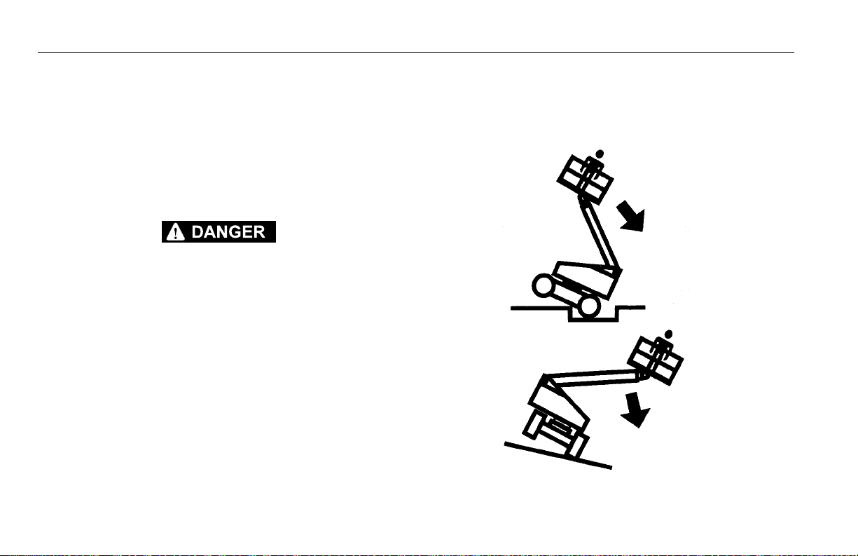
Stability
Machine stability is based on two positions which are called
FORWARD and BACKWARD stability. The machines position
of least FORWARD stability is shown in Figure 4-2., Position
of Least Forward Stability, and its position of least BACKWARD stability is shown in Figure 4-1., Position of Least
Backward Stability.
TO AVOID FORWARD OR BACKWARD TIPPING, DO NOT OVERLOAD
MACHINE OR OPERATE THE MACHINE ON AN OUT-OF-LEVEL SURFACE.
4.3 ENGINE OPERATION
NOTE: Initial starting should always be performed from the
Ground Control station.
Starting Procedure
IF ENGINE FAILS TO START PROMPTLY, DO NOT CRANK FOR AN
EXTENDED TIME. SHOULD ENGINE FAIL TO START AGAIN, ALLOW
STARTER TO “COOL OFF” FOR 2-3 MINUTES. IF ENGINE FAILS AFTER
SEVERAL ATTEMPTS, REFER TO ENGINE MAINTENANCE MANUAL.
NOTE: Diesel engines only: After turning on ignition, operator
must wait until glow plug indicator light goes out before
cranking engine.
1. Turn key of SELECT switch to GROUND. Position
POWER/EMERGENCY STOP switch to ON, then push
the ENGINE START switch until engine starts.
ALLOW ENGINE TO WARM-UP FOR A FEW MINUTES AT LOW SPEED
BEFORE APPLYING ANY LOAD.
2. After engine has had sufficient time to warm up, shut
engine off.
3. Turn SELECT switch to PLATFORM.
4-2 – JLG Lift – 3121205

4. From Platform, pull POWER/EMERGENCY STOP switch
Figure 4-1. Position of Least Backward Stability
out, then push the ENGINE START switch until engine
starts.
NOTE: Footswitch must be in released (up) position before
starter will operate. If starter operates with footswitch in
the depressed position, DO NOT OPERATE MACHINE.
Shutdown Procedure
IF AN ENGINE MALFUNCTION CAUSES AN UNSCHEDULED SHUTDOWN,
DETERMINE THE CAUSE AND CORRECT IT BEFORE RESTARTING THE
ENGINE.
1. Remove all load and allow engine to operate at low
speed for 3-5 minutes; this allows further reduction of
internal engine temperature.
2. Push POWER/EMERGENCY STOP switch in.
3. Turn Select switch to Off.
Refer to Engine Manufacturer’s manual for detailed information.
SECTION 4 - MACHINE OPERATION
3121205 – JLG Lift – 4-3

SECTION 4 - MACHINE OPERATION
Figure 4-2. Position of Least Forward Stability
4-4 – JLG Lift – 3121205

SECTION 4 - MACHINE OPERATION
4.4 TRAVELING (DRIVING)
DO NOT DRIVE WITH BOOM ABOVE HORIZONTAL EXCEPT ON A
SMOOTH, FIRM AND LEVEL SURFACE.
TO AVOID LOSS OF TRAVEL CONTROL OR “TIP OVER”, DO NOT DRIVE
MACHINE ON GRADES EXCEEDING THOSE SPECIFIED ON THE SERIAL
NUMBER PLATE.
BE SURE THE TURNTABLE LOCK IS ENGAGED BEFORE ANY EXTENDED
TRAVELING.
DO NOT DRIVE ON SIDESLOPES WHICH EXCEED 5 DEGREES.
USE EXTREME CAUTION WHEN DRIVING IN REVERSE AND AT ALL
TIMES WHEN THE PLATFORM IS ELEVATED.
BEFORE DRIVING, MAKE SURE BOOM IS POSITIONED OVER REAR
DRIVE AXLE. IF BOOM IS OVER FRONT WHEELS, STEER AND DRIVE
CONTROLS WILL BE REVERSED.
Traveling Forward and Reverse
1. At Platform Controls, pull out Emergency Stop switch
and activate footswitch.
2. Position Drive controller to FORWARD or REVERSE as
desired.
This machine is equipped with a Drive Orientation Indicator.
The yellow light on the platform control console indicates
that the boom is swung beyond the rear drive tires and the
machine may Drive/Steer in the opposite direction from the
movement of the controls. If the indicator is illuminated,
operate the Drive function in the following manner:
1. Match the black and white direction arrows on both platform control panel and the chassis to determine the
direction the machine will travel.
2. Push and release the Drive Orientation Override switch.
Within 3 seconds, slowly move the Drive control toward
the arrow matching the intended direction of machine
travel. The indicator light will flash during the 3 second
interval until the drive function is selected.
3121205 – JLG Lift – 4-5

SECTION 4 - MACHINE OPERATION
Figure 4-3. Grade and Sideslope
4-6 – JLG Lift – 3121205

SECTION 4 - MACHINE OPERATION
4.5 STEERING
Position thumb switch on Drive/Steer controller to RIGHT for
steering right, or to LEFT for steering left.
4.6 PLATFORM
Platform Level Adjustment
To Level Up or Down - Position the Platform/Level control
switch Up or Down and hold until the platform is level.
ONLY USE THE PLATFORM LEVELING OVERRIDE FUNCTION FOR
SLIGHT LEVELING OF THE PLATFORM. INCORRECT USE COULD
CAUSE THE LOAD/OCCUPANT TO SHIFT OR FALL. FAILURE TO DO SO
COULD RESULT IN DEATH OR SERIOUS INJURY.
Platform Rotation
To rotate the platform to the left or right, use the Platform
Rotate control switch to select the direction and hold until
desired position is reached.
4.7 BOOM
DO NOT SWING OR RAISE BOOM ABOVE HORIZONTAL WHEN MACHINE
IS OUT OF LEVEL.
DO NOT DEPEND ON TILT ALARM AS A LEVEL INDICATOR FOR THE
CHASSIS.
TO AVOID TIP OVER, LOWER PLATFORM TO GROUND LEVEL. THEN
DRIVE MACHINE TO A LEVEL SURFACE BEFORE RAISING BOOM.
TO AVOID SERIOUS INJURY, DO NOT OPERATE MACHINE IF ANY CONTROL LEVER OR TOGGLE SWITCH CONTROLLING PLATFORM MOVEMENT DOES NOT RETURN TO THE ‘OFF’ OR NEUTRAL POSITION WHEN
RELEASED.
IF THE PLATFORM DOES NOT STOP WHEN A CONTROL SWITCH OR
LEVER IS RELEASED, REMOVE FOOT FROM FOOTSWITCH OR USE
EMERGENCY STOP SWITCH TO STOP THE MACHINE.
3121205 – JLG Lift – 4-7

SECTION 4 - MACHINE OPERATION
Swinging the Boom
To swing boom, use SWING control switch to select RIGHT
or LEFT direction.
WHEN SWINGING THE BOOM MAKE SURE THERE IS AMPLE ROOM FOR
THE BOOM TO CLEAR SURROUNDING WALLS, PARTITIONS AND EQUIPMENT.
NOTE: When boom functions are being operated there is an
interlock that prevents the use of DRIVE and STEER functions.
Raising and Lowering the Boom
To raise and lower the Boom, position LIFT control switch or
controller to UP or DOWN and hold until desired height is
reached.
Telescoping the Boom
To extend or retract the Boom, position MAIN TELESCOPE
control switch to IN or OUT and hold until platform reaches
desired position.
4.8 SHUT DOWN AND PARK
1. Drive machine to a protected area.
2. Assure boom is fully retracted and lowered over rear
(Drive) axle; all access panels and doors closed and
secured.
3. Remove all load and allow engine to operate 3-5 minutes at LOW setting to permit reduction of engine internal temperatures.
4. At Ground Controls, turn KEY SELECT switch to (center)
OFF. Position, POWER/EMERGENCY STOP switch
(down) to OFF. Remove key.
5. Cover Platform Control console to protect instruction
placards, warning decals and operating controls from
hostile environment.
4-8 – JLG Lift – 3121205
SECTION 4 - MACHINE OPERATION
4.9 OSCILLATING AXLE LOCKOUT TEST (IF EQUIPPED)
LOCKOUT SYSTEM TEST MUST BE PERFORMED QUARTERLY, ANY TIME
A SYSTEM COMPONENT IS REPLACED, OR WHEN IMPROPER SYSTEM
OPERATION IS SUSPECTED.
Refer to Section 6.5, Oscillating Axle Lockout Test (If
Equipped) for procedure.
4.10 STEER/TOW SELECTOR (IF EQUIPPED)
DO NOT ATTEMPT TO TOW MACHINE UNLESS EQUIPPED WITH COMPLETE TOW PACKAGE FROM MANUFACTURER.
A push-pull type selector valve located adjacent to the steer
cylinder and linkage regulates oil flow in the steer circuit for
steering and towing. When steering the unit the valve knob is
pushed IN. When towing the unit the valve knob is pulled
OUT to the float position.
4.11 TOWING (IF EQUIPPED)
RUNAWAY VEHICLE/MACHINE HAZARD. MACHINE HAS NO TOWING
BRAKES. TOWING VEHICLE MUST BE ABLE TO CONTROL MACHINE AT
ALL TIMES. ON-HIGHWAY TOWING NOT PERMITTED. FAILURE TO FOLLOW INSTRUCTIONS COULD CAUSE SERIOUS INJURY OR DEATH.
MAXIMUM TOWING SPEED 8 M.P.H. (13 K.M.H.)
MAXIMUM TOWING GRADE 25%.
Prior to towing the machine, complete the following:
DO NOT TOW MACHINE WITH ENGINE OPERATING OR DRIVE HUBS
ENGAGED.
1. Retract, lower and position boom over rear drive wheels
in line with direction of travel; lock turntable.
3121205 – JLG Lift – 4-9

SECTION 4 - MACHINE OPERATION
Figure 4-4. Drive Disconnect Hub
2. Connect tow bar to front of frame with attach pins, and
tow bar to towing vehicle.
3. Disconnect drive hubs by inverting disconnect cap.Refer
to Figure 4-4., Drive Disconnect Hub.
4. Actuate steer/tow selector valve for towing; pull valve
knob OUT to float position. (This opens the steer circuit
to reservoir, allowing the steer cylinder rod free travel.)
The machine is now in the towing mode.
After towing the machine, complete the following:
1. Actuate steer/tow selector valve for steering; push valve
knob IN to the actuated position.
2. Reconnect drive hubs by inverting disconnect cap.
3. Disconnect tow bar from steering hitch and from towing
vehicle. The machine is now in the driving mode.
4-10 – JLG Lift – 3121205

SECTION 4 - MACHINE OPERATION
Figure 4-5. Towbar Connecting Points - Prior to S/N 75606
STEER SELECT
VALVE
3121205 – JLG Lift – 4-11

SECTION 4 - MACHINE OPERATION
STEER SELECT
VALVE
Figure 4-6. Towbar Connecting Points - S/N 75606 to Present
4-12 – JLG Lift – 3121205

SECTION 4 - MACHINE OPERATION
4.12 AUXILIARY POWER - NON ADE EQUIPPED MACHINES
WHEN OPERATING ON AUXILIARY POWER, DO NOT OPERATE MORE
THAN ONE FUNCTION AT A TIME. (SIMULTANEOUS OPERATION CAN
OVERLOAD THE 12-VOLT AUXILIARY PUMP MOTOR.)
A toggle type auxiliary power control switch is located on the
platform control station and another is located on the ground
control station. Operation of either switch turns on the electrically driven auxiliary hydraulic pump. This should be used in
case of failure of the main power plant. The auxiliary pump
will operate boom lift, telescope and swing. To activate auxiliary power:
Activating from the Platform Control Station
1. Position PLATFORM/GROUND SELECT KEY SWITCH to
PLATFORM.
2. Position POWER/EMERGENCY STOP switch to ON.
3. Depress and hold footswitch.
4. Operate appropriate control switch, lever or controller
for desired function and hold.
5. Position AUXILIARY POWER switch to ON and hold.
6. Release AUXILIARY POWER switch, selected control
switch, lever or controller, and footswitch.
7. Position POWER/EMERGENCY STOP switch to OFF.
Activating from the Ground Control Station
1. Position PLATFORM/GROUND SELECT KEY SWITCH to
GROUND.
2. Position POWER/EMERGENCY STOP switch to ON.
3. Operate appropriate control switch or controller for
desired function and hold.
4. Position AUXILIARY POWER switch to ON and hold.
5. Release AUXILIARY POWER switch, and appropriate
control switch or controller.
6. Position POWER/EMERGENCY STOP switch to OFF.
3121205 – JLG Lift – 4-13

SECTION 4 - MACHINE OPERATION
4.13 AUXILIARY POWER - ADE EQUIPPED MACHINES
WHEN OPERATING ON AUXILIARY POWER, DO NOT OPERATE MORE
THAN ONE FUNCTION AT A TIME. (SIMULTANEOUS OPERATION CAN
OVERLOAD THE 12-VOLT AUXILIARY PUMP MOTOR.)
A toggle type auxiliary power control switch is located on the
platform control station and another is located on the ground
control station. Operation of either switch turns on the electrically driven auxiliary hydraulic pump. This should be used in
case of failure of the main power plant. The auxiliary pump
will operate boom lift, telescope and swing. To activate auxiliary power:
Activating from the Platform Control Station
1. Position PLATFORM/GROUND SELECT KEY SWITCH to
PLATFORM.
2. Position POWER/EMERGENCY STOP switch to ON.
3. Depress and hold footswitch.
4. Position AUXILIARY POWER switch to ON and hold.
5. Operate appropriate control switch, lever or controller
for desired function and hold.
6. Release AUXILIARY POWER switch, selected control
switch, lever or controller, and footswitch.
7. Position POWER/EMERGENCY STOP switch to OFF.
Activating from the Ground Control Station
1. Position PLATFORM/GROUND SELECT KEY SWITCH to
GROUND.
2. Position POWER/EMERGENCY STOP switch to ON.
3. Position AUXILIARY POWER switch to ON and hold.
4. Operate appropriate control switch or controller for
desired function and hold.
5. Release AUXILIARY POWER switch, and appropriate
control switch or controller.
6. Position POWER/EMERGENCY STOP switch to OFF.
4-14 – JLG Lift – 3121205

SECTION 4 - MACHINE OPERATION
4.14 DUAL FUEL SYSTEM (GAS ENGINE ONLY)
The dual fuel system enables the standard gasoline engine
to run on either gasoline or LP gas.
IT IS POSSIBLE TO SWITCH FROM ONE FUEL SOURCE TO THE OTHER
WITHOUT ALLOWING THE ENGINE TO STOP. EXTREME CARE MUST BE
TAKEN AND THE FOLLOWING INSTRUCTIONS MUST BE FOLLOWED.
Changing From Gasoline to LP Gas
1. Start engine from Ground Control Station.
2. Open hand valve on LP gas supply tank by turning
counterclockwise.
3. While engine is operating on GASOLINE under a noload condition, place FUEL SELECT switch at Platform
Control to LP position.
Changing From LP Gas to Gasoline
1. With engine operating on LP under a no-load condition,
position FUEL SELECT switch at Platform Control Station to GASOLINE position.
2. Close hand valve on LP gas supply tank by turning
clockwise.
4.15 HYDRAULIC TOOL CIRCUIT INSTRUCTIONS
Tool Circuit
Operate with engine running and foot switch released.
1. Be sure hydraulic switch is “OFF”. It is located on the left
side of platform below console box.
3121205 – JLG Lift – 4-15

SECTION 4 - MACHINE OPERATION
2. Make sure the hydraulic tool about to be operated is at a
safe setting.
3. Plug tool into quick-disconnect fittings mounted on platform rail. The male quick connect is the pressure feed
line.
4. Set flow control knob to desired setting.
NOTE: Each notch in the flow control knob corresponds to
approximately 1 GPM (ex. setting 2 = 2 GPM). At setting
seven (7) the pump has reached its maximum flow rate
therefore any setting past 7 will produce no additional
flow.
4-16 – JLG Lift – 3121205

SECTION 4 - MACHINE OPERATION
5. Turn hydraulic power tool switch “ON”. Oil will now flow
to the tool. It is possible to adjust the flow control knob
during operation to achieve desired tool performance.
6. When finished, turn the hydraulic tool switch “OFF”.
7. Disconnect tool from the quick-disconnects.
TURN HYDRAULIC TOOL SWITCH TO THE “OFF” POSITION IN ORDER
TO SWITCH TOOLS.
NOTE: The tool circuit will not work with the foot switch
depressed. If the foot switch is depressed during tool circuit operation the tool circuit will stop functioning until the
foot switch is released.
NOTE: The tool is designed to operate at 2600 psi (179 Bar). If
necessary this can be adjusted for a higher or lower pressure.
NOTE: With the foot switch released to operate the tool circuit all
drive and boom functions are cut out.
4.16 TIE DOWN AND LIFTING
When transporting machine, boom must be in the stowed
mode with turntable lock pin engaged and machine securely
tied down to truck or trailer deck. Four tie down eyes are provided in the frame slab, one at each corner of the machine.
(See Figure 4-3. Machine Tie Down.)
If it becomes necessary to lift the machine using an overhead or mobile crane, it is very important that the lifting
devices are attached only to the designated lifting eyes, and
that the turntable lock pin is engaged. (See Figure 4-4. Lifting
Chart.)
NOTE: If not equipped, front lifting eyes on the S Models
machines are available. (P/N 3539590)
NOTE: Lifting eyes are provided at the front and rear in the frame
slab. Each of the four chains or slings used for lifting
machine must be adjusted individually so machine
remains level when elevated.
SECURE TURNTABLE WITH TURNTABLE LOCK BEFORE TRAVELING
LONG DISTANCES OR HAULING MACHINE ON TRUCK/TRAILER.
3121205 – JLG Lift – 4-17
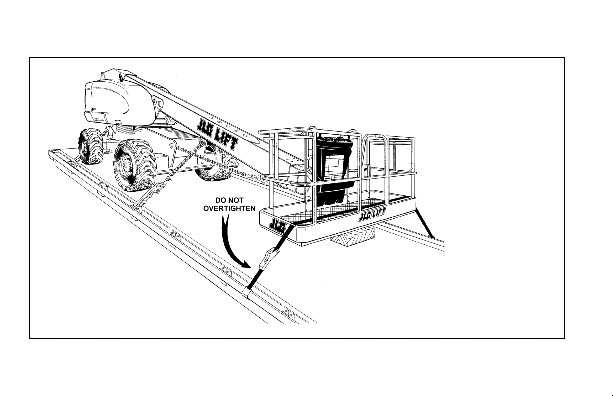
SECTION 4 - MACHINE OPERATION
Figure 4-7. Machine Tie Down
NOTE: When transporting machine over rough terrain or long distance, the
boom needs to be chocked and strapped whenever the base boom
is unable to rest on its pad. This prevents the boom from bouncing
up and down preventing possible damage while transporting.
4-18 – JLG Lift – 3121205

SECTION 4 - MACHINE OPERATION
Figure 4-8. Lifting Chart
3121205 – JLG Lift – 4-19

SECTION 4 - MACHINE OPERATION
Figure 4-9. Decal Installation - Sheet 1 of 4
4-20 – JLG Lift – 3121205

612228
33
62
26
35
26
66
26
38
64
34
21
48
47
6
23
43
33
AUS
AUS
Figure 4-10. Decal Installation - Sheet 2 of 4
SECTION 4 - MACHINE OPERATION
3121205 – JLG Lift – 4-21

SECTION 4 - MACHINE OPERATION
Figure 4-11. Decal Installation - Sheet 3 of 4
4-22 – JLG Lift – 3121205

SECTION 4 - MACHINE OPERATION
39
27,22
28
17
4115304445
101
63
65
12
29
43
61
39
42
12
24
37
24
27
27
Figure 4-12. Decal Installation - Sheet 4 of 4
3121205 – JLG Lift – 4-23

SECTION 4 - MACHINE OPERATION
Table 4-1. 600S Decal Legend - Prior to S/N 0300099060
Item # ANSI
0273867-8
1- -- -- -- -- -- -- -- - - - - -
2 1701499 1701499 1701499 1701499 1701499 1701499 1701499 1701499 1701499 1701499
3- -- -- -- -- -- -- -- - - - - -
4- -- -- -- -- -- -- -- - - - - -
5 1701509 1701509 1701509 1701509 1701509 1701509 1701509 1701509 1701509 1701509
6 1701529 1701529 1701529 1701529 1701529 1701529 1701529 1701529 1701529 1701529
7- -- -- -- -- -- -- -- - - - - -
8- -- -- -- -- -- -- -- - - - - -
9- -- -- -- -- -- -- -- - - - - -
10 1703811 1703811 1703811 1703811 1703811 1703811 1703811 1703811 1703811 1703811
11 1703814 1703814 1703814 1703814 1703814 1703814 1703814 1703814 1703814 1703814
12 1704277 1704277 1704277 1704277 1704277 1704277 1704277 1704277 1704277 1704277
13 1704412 1704412 1704412 1704412 1704412 1704412 1704412 1704412 1704412 1704412
14 - - 1705084 1705084 - - - - - - 1705084 - - - - 1705084
15 - - 1705514 - - - - - - - - 1705514 - - - - - -
16- -- -- -- -- -- -- -- -- - - -
17 3251243 3251243 3251243 - - 3251243 3251243 3251243 3251243 3251243 3251243
French
0273872-6
CE
Australian
0273875-3
Korean
0273870-9
Spanish
0273882-6
Japanese
0273888-8
Portuguese
0273885-6
Traditi onal
Chinese
0275099-8
Simplified
Chinese
1001116839-2
Australian
1001114385-1
4-24 – JLG Lift – 3121205

SECTION 4 - MACHINE OPERATION
Table 4-1. 600S Decal Legend - Prior to S/N 0300099060
Item # ANSI
0273867-8
18- -- -- -- -- -- -- -- -- - - -
19- -- -- -- -- -- -- -- -- - - -
20- -- -- -- -- -- -- -- -- - - -
21- -- -- -- -- -- -- -- -- - - -
22 1703 953 1703942 - - 1703945 1703941 1703944 1705903 1703943 1001116845 - -
23- -- -- -- -- -- -- -- -- - - -
24 1702 868 1704000 - - 1705969 1704001 - - 1705967 1001116846 1705 968 - -
25 1703797 1703924 1705921 1703927 1703923 1703926 1705895 1703925 1001116847 1705921
26 1705336 1705347 1705822 1705345 1705917 1705344 1705896 1001116849 1001116848 1705822
27 1703804 1703948 1701518 1703951 1703947 1703950 1705898 1703949 1001116850 1701518
28 1703805 1703936 1705961 1703939 1703935 1703938 1705897 1001116851 1703937 1705961
29 3252347 1703984 1705828 1703981 1703983 1703980 1705902 1703982 1001116852 1705828
30 3251813 3251813 - - - - 3251813 3251813 3251813 3251813 3251813 - -
31- -- -- -- -- -- -- -- -- - - -
32- -- -- -- -- -- -- -- -- - - -
33 1703470 1703470 1703470 1703470 1703470 1703470 1703470 1703470 1703470 1703470
34 1702631 1702631 1702631 - - 1702631 - - 1702631 - - 1702631 1702631
35 1702815 1702815 1702815 1702815 1702815 1702815 1702815 1702815 1702815 1702815
French
0273872-6
CE
Australian
0273875-3
Korean
0273870-9
Spanish
0273882-6
Japanese
0273888-8
Portuguese
0273885-6
Traditional
Chinese
0275099-8
Simplified
Chinese
1001116839-2
Australian
1001114385-1
3121205 – JLG Lift – 4-25

SECTION 4 - MACHINE OPERATION
Table 4-1. 600S Decal Legend - Prior to S/N 0300099060
Item # ANSI
0273867-8
36- -- -- -- -- -- -- -- -- - - -
37 1704096 1704099 1705978 1704103 1704098 1704102 1706380 1704101 1001116853 1705978
38 1707014 1704107 1705978 1707043 1707048 1707053 1707051 1707045 1001116854 1705978
39 1704885 1704885 1704885 1704885 1704885 1704885 1704885 1704885 - - 1704885
40 - - 1706948 - - 1706948 170694 8 - - 1706948 - - - - - -
41- -- -- -- -- -- -- -- -- - - -
42- -- -- -- -- -- -- -- -- - - -
43- -- -- -- -- -- -- -- -- - - -
44- -- -- -- -- -- -- -- -- - - -
45- -- -- -- -- -- -- -- -- - - -
46- -- -- -- -- -- -- -- -- - - -
47- -- -- -- -- -- -- -- -- - - -
48- -- -- -- -- -- -- -- -- - - -
49- -- -- -- -- -- -- -- -- - - -
50- -- -- -- -- -- -- -- -- - - -
51- -- -- -- -- -- -- -- -- - - -
52- -- -- -- -- -- -- -- -- - - -
53- -- -- -- -- -- -- -- -- - - -
French
0273872-6
CE
Australian
0273875-3
Korean
0273870-9
Spanish
0273882-6
Japanese
0273888-8
Portuguese
0273885-6
Traditi onal
Chinese
0275099-8
Simplified
Chinese
1001116839-2
Australian
1001114385-1
4-26 – JLG Lift – 3121205

SECTION 4 - MACHINE OPERATION
Table 4-1. 600S Decal Legend - Prior to S/N 0300099060
Item # ANSI
0273867-8
54- -- -- -- -- -- -- -- -- - - -
55- -- -- -- -- -- -- -- -- - - -
56- -- -- -- -- -- -- -- -- - - -
57- -- -- -- -- -- -- -- -- - - -
58- -- -- -- -- -- -- -- -- - - -
59- -- -- -- -- -- -- -- -- - - -
60- -- -- -- -- -- -- -- -- - - -
61- -- -4420051- -- -- -- -- -- -4420051
62 1700584 1700584 1700584 1700584 1702573 1700584 1700584 1700584 1700584 1700584
63 1001108493 10 01108 493 - - 1001108493 1001108493 1001108493 1001108493 1001108493 1001108493 - -
64 1706 941 1706941 - - 170694 1 1706941 1706941 1 706941 1706941 1706941 - -
65 1705 351 1705429 - - 170542 7 1705910 1705426 1 705905 1001116863 1705430 - -
66- -- -- -- -- -- -- -- -- -1001112551
French
0273872-6
CE
Australian
0273875-3
Korean
0273870-9
Spanish
0273882-6
Japanese
0273888-8
Portuguese
0273885-6
Traditional
Chinese
0275099-8
Simplified
Chinese
1001116839-2
Australian
1001114385-1
3121205 – JLG Lift – 4-27

SECTION 4 - MACHINE OPERATION
Table 4-2. 600S Decal Legend - S/N 0300099060 to Present
Item # ANSI
0273867-9
1- -- -- -- -- -- -- -- - - - - -
2 1701499 1701499 1701499 1701499 1701499 1701499 1701499 1701499 1701499 1701499
3- -- -- -- -- -- -- -- - - - - -
4- -- -- -- -- -- -- -- - - - - -
5 1701509 1701509 1701509 1701509 1701509 1701509 1701509 1701509 1701509 1701509
6 1701529 1701529 1701529 1701529 1701529 1701529 1701529 1701529 1701529 1701529
7- -- -- -- -- -- -- -- - - - - -
8- -- -- -- -- -- -- -- - - - - -
9- -- -- -- -- -- -- -- - - - - -
10 1703811 1703811 1703811 1703811 1703811 1703811 1703811 1703811 1703811 1703811
11 1703814 1703814 1703814 1703814 1703814 1703814 1703814 1703814 1703814 1703814
12 1704277 1704277 1704277 1704277 1704277 1704277 1704277 1704277 1704277 1704277
13 1704412 1704412 1704412 1704412 1704412 1704412 1704412 1704412 1704412 1704412
14 - - 1705084 1705084 - - - - - - 1705084 - - - - 1705084
15 - - 1705514 - - - - - - - - 1705514 - - - - - -
16- -- -- -- -- -- -- -- -- - - -
17 3251243 3251243 3251243 - - 3251243 3251243 3251243 3251243 3251243 3251243
18- -- -- -- -- -- -- -- -- - - -
French
0273872-7CE0273875-3
Korean
0273870-10
Spanish
0273882-7
Japanese
0273888-9
Portuguese
0273885-7
Traditi onal
Chinese
0275099-9
Simplified
Chinese
1001116839-3
Australian
1001114385-1
4-28 – JLG Lift – 3121205

SECTION 4 - MACHINE OPERATION
Table 4-2. 600S Decal Legend - S/N 0300099060 to Present
Item # ANSI
0273867-9
19- -- -- -- -- -- -- -1001117034- - - -
20- -- -- -- -- -- -- -1001117035- - - -
21- -- -- -- -- -- -- -- -- - - -
22 1703 953 1703942 - - 170394 5 1703941 1703944 170 5903 1703943 1001116845 - -
23- -- -- -- -- -- -- -- -- - - -
24 1702 868 1704000 - - 170596 9 1704001 - - 1705967 1001116846 1705968 - -
25 1703797 1703924 1705921 1703927 1703923 1703926 1705895 1703925 1001116847 1705921
26 1705336 1705347 1705822 1705345 1705917 1705344 1705896 1001116849 1001116848 1705822
27 1703804 1703948 1701518 1703951 1703947 1703950 1705898 1703949 1001116850 1701518
28 1703805 1703936 1705961 1703939 1703935 1703938 1705897 1001116851 1703937 1705961
29 3252347 1703984 1705828 1703981 1703983 1703980 1705902 1703982 1001116852 1705828
30 3251813 3251813 - - - - 3251813 3251813 3251813 3251813 3251813 - -
31- -- -- -- -- -- -- -- -- - - -
32- -- -- -- -- -- -- -- -- - - -
33 1703470 1703470 1703470 1703470 1703470 1703470 1703470 1703470 1703470 1703470
34 1702631 1702631 1702631 - - 1702631 - - 1702631 - - 1702631 1702631
35 1702815 1702815 1702815 1702815 1702815 1702815 1702815 1702815 1702815 1702815
36- -- -- -- -- -- -- -- -- - - -
French
0273872-7CE0273875-3
Korean
0273870-10
Spanish
0273882-7
Japanese
0273888-9
Portuguese
0273885-7
Traditional
Chinese
0275099-9
Simplified
Chinese
1001116839-3
Australian
1001114385-1
3121205 – JLG Lift – 4-29

SECTION 4 - MACHINE OPERATION
Table 4-2. 600S Decal Legend - S/N 0300099060 to Present
Item # ANSI
0273867-9
37 1001121800 1001121802 1705978 1001122200 1001121804 1001121807 1001121806 1001121809 1001121811 1705978
38 1001121813 1001121815 1705978 1001122201 1001121817 1001121820 1001121819 1001121822 1001121824 1705978
39 1704885 1704885 1704885 1704885 1704885 1704885 1704885 1704885 - - 1704885
40 - - 1706948 - - - - 1706948 - - 1706948 - - - - - -
41- -- -- -- -- -- -- -- -- - - -
42- -- -- -- -- -- -- -- -- - - -
43- -- -- -- -- -- -- -- -- - - -
44- -- -- -- -- -- -- -- -- - - -
45- -- -- -- -- -- -- -- -- - - -
46- -- -- -- -- -- -- -- -- - - -
47- -- -- -- -- -- -- -- -- - - -
48- -- -- -- -- -- -- -- -- - - -
49- -- -- -- -- -- -- -- -- - - -
50- -- -- -- -- -- -- -- -- - - -
51- -- -- -- -- -- -- -- -- - - -
52- -- -- -- -- -- -- -- -- - - -
53- -- -- -- -- -- -- -- -- - - -
54- -- -- -- -- -- -- -- -- - - -
French
0273872-7CE0273875-3
Korean
0273870-10
Spanish
0273882-7
Japanese
0273888-9
Portuguese
0273885-7
Traditi onal
Chinese
0275099-9
Simplified
Chinese
1001116839-3
Australian
1001114385-1
4-30 – JLG Lift – 3121205

SECTION 4 - MACHINE OPERATION
Table 4-2. 600S Decal Legend - S/N 0300099060 to Present
Item # ANSI
0273867-9
55- -- -- -- -- -- -- -- -- - - -
56- -- -- -- -- -- -- -- -- - - -
57- -- -- -- -- -- -- -- -- - - -
58- -- -- -- -- -- -- -- -- - - -
59- -- -- -- -- -- -- -- -- - - -
60- -- -- -- -- -- -- -- -- - - -
61- -- -4420051- -- -- -- -- -- -4420051
62 1700584 1700584 1700584 1700584 1702573 1700584 1700584 1700584 1700584 1700584
63 1001108493 10 01108 493 - - 1001108493 1001108493 1001108493 1001108493 1001108493 1001108493 - -
64 1706 941 1706941 - - 170694 1 1706941 1706941 1 706941 1706941 1706941 - -
65 1705 351 1705429 - - 170542 7 1705910 1705426 1 705905 1001116863 1705430 - -
66- -- -- -- -- -- -- -- -- -1001112551
French
0273872-7CE0273875-3
Korean
0273870-10
Spanish
0273882-7
Japanese
0273888-9
Portuguese
0273885-7
Traditional
Chinese
0275099-9
Simplified
Chinese
1001116839-3
Australian
1001114385-1
3121205 – JLG Lift – 4-31

SECTION 4 - MACHINE OPERATION
Table 4-3. 600SJ Decal Legend
Item # ANSI
0273868-6
1- -- -- -- -- -- - - - - -
2 1701499 1701499 1701499 1701499 1701499 1701499 1701499 1701499
3- -- -- -- -- -- - - - - -
4- -- -- -- -- -- - - - - -
5 1701509 1701509 1701509 1701509 1701509 1701509 1701509 1701509
6 1701529 1701529 1701529 1701529 1701529 1701529 1701529 1701529
7- -- -- -- -- -- - - - - -
8- -- -- -- -- -- - - - - -
9- -- -- -- -- -- - - - - -
10 1703811 1703811 1703811 1703811 1703811 1703811 1703811 1703811
11 1703814 1703814 1703814 1703814 1703814 1703814 1703814 1703814
12 1704277 1704277 1704277 1704277 1704277 1704277 1704277 1704277
13 1704412 1704412 1704412 1704412 1704412 1704412 1704412 1704412
14 - - 1705084 1705084 - - - - - - - - 1705084
15 - - 1705514 1705514 - - - - - - - - 1705514
16- -- -- -- -- -- -- - - -
17 - - 3251243 3251243 3251 243 3251243 3251243 32512 43 3251243
CE
Australian
0273876-4
French
0273873-6
Spanish
0273883-7
Japanese
600SJ
0273889-7
Portuguese
600SJ
0273886-7
Korean
1001112941-2
Australian
1001114386-1
4-32 – JLG Lift – 3121205

Table 4-3. 600SJ Decal Legend
SECTION 4 - MACHINE OPERATION
Item # ANSI
0273868-6
18- -- -- -- -- -- -- - - -
19- -- -- -- -- -- -- - - -
20- -- -- -- -- -- -- - - -
21- -- -- -- -- -- -- - - -
22 1703 953 - - 1703942 170394 1 1703944 1705903 170 3945 - -
23- -- -- -- -- -- -- - - -
24 1702 868 - - 1704000 170400 1 - - 1705967 17059 69 - -
25 1703797 1705921 1703924 1703923 1703926 1705895 1703927 1705921
26 1705336 1705822 1705347 1705917 1705344 1705896 1705345 1705822
27 1703804 1701518 1703948 1703947 1703950 1705898 1703951 1701518
28 1703805 1705961 1703936 1703935 1703938 1705897 1703939 1705961
29 - - 1705828 1703984 1703 983 1703980 1705902 17039 81 1705828
30 3251 813 - - 3251813 325181 3 3251813 3251813 - - - -
31 - - - - - - - - 1705494 - - - - - -
32- -- -- -- -- -- -- - - -
33 1703471 1703471 1703471 1703471 1703471 1703471 1703471 1703471
34 1702631 1702631 1702631 1702631 1702631 1702631 1702631 1702631
35 1702816 1702816 1702816 1702816 1702816 1702816 1702816 1702816
CE
Australian
0273876-4
French
0273873-6
Spanish
0273883-7
Japanese
600SJ
0273889-7
Portuguese
600SJ
0273886-7
Korean
1001112941-2
Australian
1001114386-1
3121205 – JLG Lift – 4-33

SECTION 4 - MACHINE OPERATION
Table 4-3. 600SJ Decal Legend
Item # ANSI
0273868-6
36- -- -- -- -- -- -- - - -
37 1701645 1705978 1707055 1707056 1707058 1707057 1707058 1705978
38 1707013 1705978 1707047 1707049 1707054 1707052 1707042 1705978
39 1704885 1704885 1704885 1704885 1704885 1704885 1704885 1704885
40 1706 948 - - 1706948 170694 8 1706948 1706948 170 6948 - -
41- -- -- -- -- -- -- - - -
42- -- -- -- -- -- -- - - -
43- -- -- -- -- -- -- - - -
44- -- -- -- -- -- -- - - -
45- -- -- -- -- -- -- - - -
46- -- -- -- -- -- -- - - -
47- -- -- -- -- -- -- - - -
48- -- -- -- -- -- -- - - -
49- -- -- -- -- -- -- - - -
50- -- -- -- -- -- -- - - -
51- -- -- -- -- -- -- - - -
52- -- -- -- -- -- -- - - -
53- -- -- -- -- -- -- - - -
CE
Australian
0273876-4
French
0273873-6
Spanish
0273883-7
Japanese
600SJ
0273889-7
Portuguese
600SJ
0273886-7
Korean
1001112941-2
Australian
1001114386-1
4-34 – JLG Lift – 3121205

Table 4-3. 600SJ Decal Legend
SECTION 4 - MACHINE OPERATION
Item # ANSI
0273868-6
54- -- -- -- -- -- -- - - -
55- -- -- -- -- -- -- - - -
56- -- -- -- -- -- -- - - -
57- -- -- -- -- -- -- - - -
58- -- -- -- -- -- -- - - -
59- -- -- -- -- -- -- - - -
60- -- -- -- -- -- -- - - -
61 - - 4420051 - - - - - - - - - - 44200 51
62 1700584 1700584 1700584 1702573 1700584 1700584 1700584 1700584
63 1001108493 - - 1001108493 1001108493 1001108493 1001108493 1001108493 - -
64 1706 941 - - 1706941 170694 1 1706941 1706941 170 6941 - -
65 1705 351 - - 1705429 170591 0 1705426 1705095 170 5427 - -
66- -- -- -- -- -- -- -1001112551
CE
Australian
0273876-4
French
0273873-6
Spanish
0273883-7
Japanese
600SJ
0273889-7
Portuguese
600SJ
0273886-7
Korean
1001112941-2
Australian
1001114386-1
3121205 – JLG Lift – 4-35

SECTION 4 - MACHINE OPERATION
Table 4-4. 660SJ Decal Legend - Prior to S/N 0300099060
Item # ANSI
0273869-7
1- -- -- -- -- -- -- -- - - -
2 1701499 1701499 1701499 1701499 1701499 1701499 1701499 1701499 1701499
3- -- -- -- -- -- -- -- - - -
4- -- -- -- -- -- -- -- - - -
5 1701509 1701509 1701509 1701509 1701509 1701509 1701509 1701509 1701509
6 1701529 1701529 1701529 1701529 1701529 1701529 1701529 1701529 1701529
7- -- -- -- -- -- -- -- - - -
8- -- -- -- -- -- -- -- - - -
9- -- -- -- -- -- -- -- - - -
10 1703811 1703811 1703811 1703811 1703811 1703811 1703811 1703811 1703811
11 1703814 1703814 1703814 1703814 1703814 1703814 1703814 1703814 1703814
12 1704277 1704277 1704277 1704277 1704277 1704277 1704277 1704277 1704277
13 1704412 1704412 1704412 1704412 1704412 1704412 1704412 1704412 1704412
14 - - - - 1705084 - - - - 1705084 1705084 1705084 1705084
15 - - 1705514 - - - - - - 1705514 1705514 1705514 - -
16- -- -- -- -- -- -- -- - - -
17 3251243 3251243 3251243 - - - - 3251243 3251243 3251243 3251243
Canadian
French
0273874-6
CE
Australian
0273877-4
Korean
0274925-9
Tradit ional
Chinese
0273871-10
Spanish
0273884-7
Japanese
0273890-9
Portuguese
0273887-7
Australian
1001114387-1
4-36 – JLG Lift – 3121205

SECTION 4 - MACHINE OPERATION
Table 4-4. 660SJ Decal Legend - Prior to S/N 0300099060
Item # ANSI
0273869-7
18- -- -- -- -- -- -- -- - - -
19- -- -- -- -1001117034- -- -- - - -
20- -- -- -- -1001117035- -- -- - - -
21- -- -- -- -- -- -- -- - - -
22 1703953 1703942 - - 1703945 1703943 1703941 1703944 1705903 - -
23- -- -- -- -- -- -- -- - - -
24 170 2868 1704000 - - 1705969 1001116846 1704001 - - 1705967 - -
25 1703797 1703924 1705921 1703927 1703925 1703923 1703926 1705895 1705921
26 1705336 1705347 1705822 1705345 1001116849 1705917 1705344 1705896 1705822
27 1703804 1703948 1701518 1703951 1703949 1703947 1703950 1705898 1701518
28 1703805 1703936 1705961 1703939 1001116851 1703935 1703938 1705897 1705961
29 - - 1703984 1705828 1703981 1703982 1703983 1703980 1705902 1705828
30 325 1813 3251813 - - - - 3251813 32 51813 3251813 3251813 - -
31- -- -- -- -- -- -- -- - - -
32- -- -- -- -- -- -- -- - - -
33 1703472 1703472 1703472 1703470 1703472 1703472 1703472 1703472 1703472
34 1702631 1702631 1702631 - - - - 1702631 - - 1702631 1702631
35 1702817 1702817 1702817 1702817 1702817 1702817 1702817 1702817 1702817
Canadian
French
0273874-6
CE
Australian
0273877-4
Korean
0274925-9
Tradit ional
Chinese
0273871-10
Spanish
0273884-7
Japanese
0273890-9
Portuguese
0273887-7
Australian
1001114387-1
3121205 – JLG Lift – 4-37

SECTION 4 - MACHINE OPERATION
Table 4-4. 660SJ Decal Legend - Prior to S/N 0300099060
Item # ANSI
0273869-7
36- -- -- -- -- -- -- -- - - -
37 1701645 1707055 1705978 1707058 1707060 1707056 1707059 1707057 1705978
38 1707013 1707047 1705978 1707042 1707044 1707049 1707054 1707052 1705978
39 1704885 1704885 1704885 1704885 1704885 1704885 1704885 1704885 1704885
40 - - 1706948 - - - - - - 1706948 - - 1706948 - -
41- -- -- -- -- -- -- -- - - -
42- -- -- -- -- -- -- -- - - -
43- -- -- -- -- -- -- -- - - -
44- -- -- -- -- -- -- -- - - -
45- -- -- -- -- -- -- -- - - -
46- -- -- -- -- -- -- -- - - -
47- -- -- -- -- -- -- -- - - -
48- -- -- -- -- -- -- -- - - -
49- -- -- -- -- -- -- -- - - -
50- -- -- -- -- -- -- -- - - -
51- -- -- -- -- -- -- -- - - -
52- -- -- -- -- -- -- -- - - -
53- -- -- -- -- -- -- -- - - -
Canadian
French
0273874-6
CE
Australian
0273877-4
Korean
0274925-9
Tradit ional
Chinese
0273871-10
Spanish
0273884-7
Japanese
0273890-9
Portuguese
0273887-7
Australian
1001114387-1
4-38 – JLG Lift – 3121205

SECTION 4 - MACHINE OPERATION
Table 4-4. 660SJ Decal Legend - Prior to S/N 0300099060
Item # ANSI
0273869-7
54- -- -- -- -- -- -- -- - - -
55- -- -- -- -- -- -- -- - - -
56- -- -- -- -- -- -- -- - - -
57- -- -- -- -- -- -- -- - - -
58- -- -- -- -- -- -- -- - - -
59- -- -- -- -- -- -- -- - - -
60- -- -- -- -- -- -- -- - - -
61 - - - - 4420051 - - - - - - - - - - 4420051
62 1700584 1700584 1700584 1700584 1700584 1702573 1700584 1700584 1700584
63 1001108493 1 0011084 93 - - 1001108493 1001108493 10011 08493 1001108493 1001108493 - -
64 1706941 1706941 - - 1706941 1706941 1706941 1706941 1706941 - -
65 170 5351 1705429 - - 1705427 1001116863 1705910 1705426 1705905 - -
66- -- -- -- -- -- -- -- -1001112551
Canadian
French
0273874-6
CE
Australian
0273877-4
Korean
0274925-9
Tradit ional
Chinese
0273871-10
Spanish
0273884-7
Japanese
0273890-9
Portuguese
0273887-7
Australian
1001114387-1
3121205 – JLG Lift – 4-39

SECTION 4 - MACHINE OPERATION
Table 4-5. 660SJ Decal Legend - S/N 0300099060 to Present
Item # ANSI
0273869-8
1- -- -- -- -- - - - - -- -- - - -
2 1701499 1701499 1701499 1701499 1701499 1701499 1701499 1701499 1701499 1701499
3- -- -- -- -- - - - - -- -- - - -
4- -- -- -- -- - - - - -- -- - - -
5 1701509 1701509 1701509 1701509 1701509 1701509 1701509 1701509 1701509 1701509
6 1701529 1701529 1701529 1701529 1701529 1701529 1701529 1701529 1701529 1701529
7- -- -- -- -- - - - - -- -- - - -
8- -- -- -- -- - - - - -- -- - - -
9- -- -- -- -- - - - - -- -- - - -
10 1703811 1703811 1703811 1703811 1703811 1703811 1703811 1703811 1703811 1703811
11 1703814 1703814 1703814 1703814 1703814 1703814 1703814 1703814 1703814 1703814
12 1704277 1704277 1704277 1704277 1704277 1704277 1704277 1704277 1704277 1704277
13 1704412 1704412 1704412 1704412 1704412 1704412 1704412 1704412 1704412 1704412
14 - - - - 1705084 - - - - - - 1705084 1705084 1705084 1705084
15 - - 1705514 - - - - - - - - 1705514 1705514 170 5514 - -
16- -- -- -- -- - - - - -- -- - - -
17 3251243 3251243 3251243 - - - - - - 3251243 3251243 3251243 3251243
Canadian
French
0273874-7
CE
Australian
0273877-4
Korean
0274925-10
Tradit ional
Chinese
0273871-11
Simplified
Chinese
1001117939-3
Spanish
0273884-8
Japanese
0273890-10
Portuguese
0273887-8
Australian
1001114387-1
4-40 – JLG Lift – 3121205

SECTION 4 - MACHINE OPERATION
Table 4-5. 660SJ Decal Legend - S/N 0300099060 to Present
Item # ANSI
0273869-8
18- -- -- -- -- - - - - -- -- - - -
19- -- -- -- -1001117034- - - -- -- - - -
20- -- -- -- -1001117035- - - -- -- - - -
21- -- -- -- -- - - - - -- -- - - -
22 170 3953 1703942 - - 1703945 1703943 1001116845 170394 1 1703944 1705903 - -
23- -- -- -- -- - - - - -- -- - - -
24 170 2868 1704000 - - 1705969 1001116846 17059 68 1704001 - - 1705967 - -
25 1703797 1703924 1705921 1703927 1703925 1001116847 1703923 1703926 1705895 1705921
26 1705336 1705347 1705822 1705345 1001116849 1001116848 1705917 1705344 1705896 1705822
27 1703804 1703948 1701518 1703951 1703949 1001116850 1703947 1703950 1705898 1701518
28 1703805 1703936 1705961 1703939 1001116851 1703937 1703935 1703938 1705897 1705961
29 - - 1703984 1705828 1703981 1703982 1001116852 1703983 1703980 1705902 1705828
30 325 1813 3251813 - - - - 3251813 32518 13 3251813 3251813 3251813 - -
31- -- -- -- -- - - - - -- -- - - -
32- -- -- -- -- - - - - -- -- - - -
33 1703472 1703472 1703472 1703470 1703472 1703472 1703472 1703472 1703472 1703472
34 1702631 1702631 1702631 - - - - - - 1702631 - - 1702631 1702631
35 1702817 1702817 1702817 1702817 1702817 1702817 1702817 1702817 1702817 1702817
Canadian
French
0273874-7
CE
Australian
0273877-4
Korean
0274925-10
Tradit ional
Chinese
0273871-11
Simplified
Chinese
1001117939-3
Spanish
0273884-8
Japanese
0273890-10
Portuguese
0273887-8
Australian
1001114387-1
3121205 – JLG Lift – 4-41

SECTION 4 - MACHINE OPERATION
Table 4-5. 660SJ Decal Legend - S/N 0300099060 to Present
Item # ANSI
0273869-8
36- -- -- -- -- - - - - -- -- - - -
37 1001121801 1001121803 1705978 1001121918 1001121810 1001121812 1001121805 1001121808 1001121656 1705978
38 1001121814 1001121816 1705978 1001121921 1001121823 1001121825 1001121818 1001121821 1001121655 1705978
39 1704885 1704885 1704885 1704885 1704885 1704885 1704885 1704885 1704885 1704885
40 - - 1706948 - - - - - - - - 1706948 - - 1706948 - -
41- -- -- -- -- - - - - -- -- - - -
42- -- -- -- -- - - - - -- -- - - -
43- -- -- -- -- - - - - -- -- - - -
44- -- -- -- -- - - - - -- -- - - -
45- -- -- -- -- - - - - -- -- - - -
46- -- -- -- -- - - - - -- -- - - -
47- -- -- -- -- - - - - -- -- - - -
48- -- -- -- -- - - - - -- -- - - -
49- -- -- -- -- - - - - -- -- - - -
50- -- -- -- -- - - - - -- -- - - -
51- -- -- -- -- - - - - -- -- - - -
52- -- -- -- -- - - - - -- -- - - -
53- -- -- -- -- - - - - -- -- - - -
Canadian
French
0273874-7
CE
Australian
0273877-4
Korean
0274925-10
Tradit ional
Chinese
0273871-11
Simplified
Chinese
1001117939-3
Spanish
0273884-8
Japanese
0273890-10
Portuguese
0273887-8
Australian
1001114387-1
4-42 – JLG Lift – 3121205
 Loading...