

®
Operation and Safety Manual
Original Instructions - Keep this manual with the machine at all times.
Boom Lift Models
400S
400SJ
ANSI
3121216
September 18, 2014


FOREWORD
FOREWORD
This manual is a very important tool! Keep it with the machine at all times.
The purpose of this manual is to provide owners, users, operators, lessors, and lessees with the precautions and operating
procedures essential for the safe and proper machine operation for its intended purpose.
Due to continuous product improvements, JLG Industries, Inc. reserves the right to make specification changes without
prior notification. Contact JLG Industries, Inc. for updated information.
3121216 – JLG Lift – a
FOREWORD
SAFETY ALERT SYMBOLS AND SAFETY SIGNAL WORDS
This is the Safety Alert Symbol. It is used to alert you to the potential personal injury
hazards. Obey all safety messages that follow this symbol to avoid possible injury or
death
INDICATES AN IMMINENTLY HAZARDOUS SITUATION. IF NOT AVOIDED, WILL
RESULT IN SERIOUS INJURY OR DEATH. THIS DECAL WILL HAVE A RED BACKGROUND.
INDICATES A POTENTIALLY HAZARDOUS SITUATION. IF NOT AVOIDED, COULD
RESULT IN SERIOUS INJURY OR DEATH. THIS DECAL WILL HAVE AN ORANGE BACKGROUND.
INDICATES A POTENTIALLY HAZARDOUS SITUATION. IF NOT AVOIDED, MAY RESULT
IN MINOR OR MODERATE INJURY. IT MAY ALSO ALERT AGAINST UNSAFE PRACTICES.
THIS DECAL WILL HAVE A YELLOW BACKGROUND.
INDICATES INFORMATION OR A COMPANY POLICY THAT RELATES DIRECTLY OR INDIRECTLY TO THE SAFETY OF PERSONNEL OR PROTECTION OF PROPERTY.
b – JLG Lift – 3121216

THIS PRODUCT MUST COMPLY WITH ALL SAFETY RELATED BULLETINS. CONTACT JLG
INDUSTRIES, INC. OR THE LOCAL AUTHORIZED JLG REPRESENTATIVE FOR INFORMATION REGARDING SAFETY-RELATED BULLETINS WHICH MAY HAVE BEEN ISSUED FOR
THIS PRODUCT.
JLG INDUSTRIES, INC. SENDS SAFETY RELATED BULLETINS TO THE OWNER OF
RECORD OF THIS MACHINE. CONTACT JLG INDUSTRIES, INC. TO ENSURE THAT THE
CURRENT OWNER RECORDS ARE UPDATED AND ACCURATE.
JLG INDUSTRIES, INC. MUST BE NOTIFIED IMMEDIATELY IN ALL INSTANCES WHERE
JLG PRODUCTS HAVE BEEN INVOLVED IN AN ACCIDENT INVOLVING BODILY INJURY
OR DEATH OF PERSONNEL OR WHEN SUBSTANTIAL DAMAGE HAS OCCURRED TO PERSONAL PROPERTY OR THE JLG PRODUCT.
For:
• Accident Reporting
•Product Safety
Publications
• Current Owner Updates
• Questions Regarding Product Safety
Contact:
Product Safety and Reliability Department
JLG Industries, Inc.
13224 Fountainhead Plaza
Hagerstown, MD 21742
USA
or Your Local JLG Office
(See addresses on inside of manual cover)
In USA:
Toll Free: 877-JLG-SAFE (877-554-7233)
Outside USA:
Phone: 240-420-2661
Fax: 301-745-3713
E-mail: ProductSafety@JLG.com
FOREWORD
• Standards and Regulations
Compliance Information
• Questions Regarding
Special Product Applications
• Questions Regarding
Product Modifications
3121216 – JLG Lift – c

FOREWORD
REVISION LOG
Original Issue - June 8, 2005
Revised - October 14, 2005
Revised - February 8, 2006
Revised - May 24, 2006
Revised - July 31, 2007
Revised - October 8, 2008
Revised - November 5, 2009
Revised - October 6, 2011
Revised - May 25, 2012
Revised - September 18, 2014
d – JLG Lift – 3121216

TABLE OF CONTENTS
SECTION - PARAGRAPH, SUBJECT PAGE SECTION - PARAGRAPH, SUBJECT PAGE
SECTION - 1 - SAFETY PRECAUTIONS
1.1 GENERAL . . . . . . . . . . . . . . . . . . . . . . . . . . . . . . . . .1-1
1.2 PRE-OPERATION . . . . . . . . . . . . . . . . . . . . . . . . . . .1-1
Operator Training and Knowledge . . . . . . . . . . . 1-1
Workplace Inspection. . . . . . . . . . . . . . . . . . . . . 1-2
Machine Inspection . . . . . . . . . . . . . . . . . . . . . . 1-3
1.3 OPERATION . . . . . . . . . . . . . . . . . . . . . . . . . . . . . . .1-3
General . . . . . . . . . . . . . . . . . . . . . . . . . . . . . . . . 1-3
Trip and Fall Hazards . . . . . . . . . . . . . . . . . . . . . 1-4
Electrocution Hazards . . . . . . . . . . . . . . . . . . . . 1-5
Tipping Hazards . . . . . . . . . . . . . . . . . . . . . . . . . 1-7
Crushing and Collision Hazards. . . . . . . . . . . . 1-10
1.4 TOWING, LIFTING, AND HAULING . . . . . . . . . . . .1-11
1.5 MAINTENANCE . . . . . . . . . . . . . . . . . . . . . . . . . . .1-11
Maintenance Hazards. . . . . . . . . . . . . . . . . . . . 1-11
Battery Hazards . . . . . . . . . . . . . . . . . . . . . . . . 1-13
SECTION - 2 - USER RESPONSIBILITIES, MACHINE
PREPARATION, AND INSPECTION
2.1 PERSONNEL TRAINING . . . . . . . . . . . . . . . . . . . . .2-1
Operator Training . . . . . . . . . . . . . . . . . . . . . . . . 2-1
Training Supervision. . . . . . . . . . . . . . . . . . . . . . 2-1
Operator Responsibility . . . . . . . . . . . . . . . . . . . 2-1
2.2 PREPARATION, INSPECTION,
AND MAINTENANCE . . . . . . . . . . . . . . . . . . . . . . 2-2
Pre-Start Inspection. . . . . . . . . . . . . . . . . . . . . . . 2-5
Functional Check . . . . . . . . . . . . . . . . . . . . . . . . 2-6
Walk-Around inspection . . . . . . . . . . . . . . . . . . . 2-9
2.3 OSCILLATING AXLE LOCKOUT TEST
(IF EQUIPPED) . . . . . . . . . . . . . . . . . . . . . . . . . . 2-11
SECTION - 3 - MACHINE CONTROLS AND INDICATORS
3.1 GENERAL . . . . . . . . . . . . . . . . . . . . . . . . . . . . . . . . 3-1
3.2 CONTROLS AND INDICATORS . . . . . . . . . . . . . . . 3-1
Ground Controls . . . . . . . . . . . . . . . . . . . . . . . . . 3-2
Ground Control Indicator Panel . . . . . . . . . . . . . 3-7
Platform Station . . . . . . . . . . . . . . . . . . . . . . . . . 3-10
Platform Control Indicator Panel . . . . . . . . . . . . 3-16
SECTION - 4 - MACHINE OPERATION
4.1 DESCRIPTION. . . . . . . . . . . . . . . . . . . . . . . . . . . . . 4-1
4.2 OPERATING CHARACTERISTICS
AND LIMITATIONS . . . . . . . . . . . . . . . . . . . . . . . . 4-1
Capacities . . . . . . . . . . . . . . . . . . . . . . . . . . . . . . 4-1
Stability . . . . . . . . . . . . . . . . . . . . . . . . . . . . . . . . 4-2
4.3 ENGINE OPERATION . . . . . . . . . . . . . . . . . . . . . . . 4-4
Starting Procedure . . . . . . . . . . . . . . . . . . . . . . . 4-4
Shutdown Procedure . . . . . . . . . . . . . . . . . . . . . 4-5
3121216 – JLG Lift – i

TABLE OF CONTENTS
SECTION - PARAGRAPH, SUBJECT PAGE SECTION - PARAGRAPH, SUBJECT PAGE
4.4 TRAVELING (DRIVING) . . . . . . . . . . . . . . . . . . . . . . 4-7
Traveling Forward or Reverse . . . . . . . . . . . . . . 4-9
4.5 STEERING . . . . . . . . . . . . . . . . . . . . . . . . . . . . . . . 4-10
4.6 PARKING AND STOWING . . . . . . . . . . . . . . . . . . . 4-10
4.7 PLATFORM . . . . . . . . . . . . . . . . . . . . . . . . . . . . . . 4-10
Loading from Ground Level. . . . . . . . . . . . . . . 4-10
Loading From Positions Above Ground Level 4-10
Platform Level Adjustment . . . . . . . . . . . . . . . . 4-11
Platform Rotation . . . . . . . . . . . . . . . . . . . . . . . 4-11
4.8 BOOM . . . . . . . . . . . . . . . . . . . . . . . . . . . . . . . . . . 4-11
Swinging the Boom . . . . . . . . . . . . . . . . . . . . . 4-12
Raising and Lowering the Main Boom . . . . . . 4-12
Telescoping the Main Boom . . . . . . . . . . . . . . 4-12
4.9 AUXILIARY POWER - NON ADE EQUIPPED
MACHINES . . . . . . . . . . . . . . . . . . . . . . . . . . . . . 4-13
Activating from the Platform Control Station . . 4-13
Activating from the Ground Control Station . . 4-13
4.10 AUXILIARY POWER -
ADE EQUIPPED MACHINES. . . . . . . . . . . . . . . . 4-14
Activating from the Platform Control Station . . 4-14
Activating from the Ground Control Station . . 4-14
4.11 SHUT DOWN AND PARK . . . . . . . . . . . . . . . . . . . 4-15
4.12 TIE DOWN AND LIFTING. . . . . . . . . . . . . . . . . . . . 4-15
4.13 TOWING. . . . . . . . . . . . . . . . . . . . . . . . . . . . . . . . . 4-19
4.14 PLACARDS AND DECALS. . . . . . . . . . . . . . . . . . . 4-20
SECTION - 5 - EMERGENCY PROCEDURES
5.1 GENERAL . . . . . . . . . . . . . . . . . . . . . . . . . . . . . . . . .5-1
5.2 INCIDENT NOTIFICATION . . . . . . . . . . . . . . . . . . . .5-1
5.3 EMERGENCY OPERATION . . . . . . . . . . . . . . . . . . .5-1
Operator Unable to Control Machine . . . . . . . . . 5-1
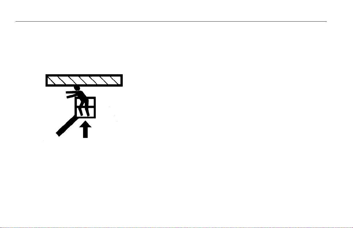
Platform or Boom Caught Overhead . . . . . . . . . 5-2
5.4 EMERGENCY TOWING PROCEDURES. . . . . . . . .5-2
SECTION - 6 - GENERAL SPECIFICATIONS & OPERATOR
MAINTENANCE
6.1 INTRODUCTION. . . . . . . . . . . . . . . . . . . . . . . . . . . .6-1
6.2 OPERATING SPECIFICATIONS. . . . . . . . . . . . . . . .6-1
Capacities . . . . . . . . . . . . . . . . . . . . . . . . . . . . . . 6-5
Engine. . . . . . . . . . . . . . . . . . . . . . . . . . . . . . . . . 6-6
Tires . . . . . . . . . . . . . . . . . . . . . . . . . . . . . . . . . . 6-9
Hydraulic Oil . . . . . . . . . . . . . . . . . . . . . . . . . . . 6-10
Critical Stability Weights . . . . . . . . . . . . . . . . . . 6-13
Serial Number Location . . . . . . . . . . . . . . . . . . 6-14
6.3 OPERATOR MAINTENANCE . . . . . . . . . . . . . . . . .6-28
6.4 TIRES & WHEELS . . . . . . . . . . . . . . . . . . . . . . . . .6-39
Tire Inflation . . . . . . . . . . . . . . . . . . . . . . . . . . . 6-39
Tire Damage . . . . . . . . . . . . . . . . . . . . . . . . . . . 6-39
Tire Replacement . . . . . . . . . . . . . . . . . . . . . . . 6-39
Wheel Replacement . . . . . . . . . . . . . . . . . . . . . 6-40
Wheel Installation . . . . . . . . . . . . . . . . . . . . . . . 6-40
ii – JLG Lift – 3121216

TABLE OF CONTENTS
SECTION - PARAGRAPH, SUBJECT PAGE SECTION - PARAGRAPH, SUBJECT PAGE
6.5 DRAINING OIL BUILD UP FROM THE PROPANE
REGULATOR (PRIOR TO S/N 0300109274) . . . .6-42
6.6 PROPANE FUEL FILTER REPLACEMENT. . . . . . .6-44
Removal . . . . . . . . . . . . . . . . . . . . . . . . . . . . . . 6-44
Installation. . . . . . . . . . . . . . . . . . . . . . . . . . . . . 6-44
6.7 PROPANE FUEL SYSTEM PRESSURE RELIEF . .6-46
6.8 SUPPLEMENTAL INFORMATION . . . . . . . . . . . . .6-46
SECTION - 7 - INSPECTION AND REPAIR LOG
LIST OF FIGURES
2-1. Basic Nomenclature. . . . . . . . . . . . . . . . . . . . . . . . . . . . . . . . . . 2-4
2-2. Daily Walk-Around Inspection - Sheet 1 of 3 . . . . . . . . . . 2-8
2-3. Daily Walk-Around Inspection - Sheet 2 of 3 . . . . . . . . . . 2-9
2-4. Daily Walk-Around Inspection - Sheet 3 of 3 . . . . . . . . . 2-10
3-1. Ground Control Station - S Models . . . . . . . . . . . . . . . . . . . 3-3
3-2. Ground Control Station - SJ Models. . . . . . . . . . . . . . . . . . . 3-4
3-3. Ground Control Indicator Panel
(Prior to S/N 93233) . . . . . . . . . . . . . . . . . . . . . . . . . . . . . . . . . 3-7
3-4. Ground Control Indicator Panel
(S/N 93233 to Present) . . . . . . . . . . . . . . . . . . . . . . . . . . . . . . 3-8
3-5. Platform Control Console . . . . . . . . . . . . . . . . . . . . . . . . . . . 3-11
3-6. Platform Control Console - w/Drive Orientation . . . . . . 3-12
3-7. Platform Control Indicator Panel . . . . . . . . . . . . . . . . . . . . 3-17
3-8. Platform Control Indicator Panel -
w/Drive Orientation . . . . . . . . . . . . . . . . . . . . . . . . . . . . . . . 3-17
3-9. Fuel Indicator. . . . . . . . . . . . . . . . . . . . . . . . . . . . . . . . . . . . . . . 3-18
4-1. Position Of Least Backward Stability . . . . . . . . . . . . . . . . . . 4-2
4-2. Position Of Least Forward Stability . . . . . . . . . . . . . . . . . . . 4-3
4-3. Grades and Sideslopes . . . . . . . . . . . . . . . . . . . . . . . . . . . . . . . 4-8
4-4. Machine Tie Down - 400S Models. . . . . . . . . . . . . . . . . . . . 4-16
4-5. Machine Tie Down - 460SJ Models. . . . . . . . . . . . . . . . . . . 4-17
4-6. Lifting and Tie Down. . . . . . . . . . . . . . . . . . . . . . . . . . . . . . . . 4-18
4-7. Drive Disconnect Hub. . . . . . . . . . . . . . . . . . . . . . . . . . . . . . . 4-19
4-8. Decal Installation - Sheet 1 of 4 . . . . . . . . . . . . . . . . . . . . . . 4-21
3121216 – JLG Lift – iii

TABLE OF CONTENTS
SECTION - PARAGRAPH, SUBJECT PAGE SECTION - PARAGRAPH, SUBJECT PAGE
4-9. Decal Installation - Sheet 2 of 4. . . . . . . . . . . . . . . . . . . . . . 4-22
4-10. Decal Installation - Sheet 3 of 4. . . . . . . . . . . . . . . . . . . . . . 4-23
4-11. Decal Installation - Sheet 4 of 4. . . . . . . . . . . . . . . . . . . . . . 4-24
6-1. Serial Number Location . . . . . . . . . . . . . . . . . . . . . . . . . . . . . 6-14
6-2. Engine Operating Temperature Specifications -
Deutz - Sheet 1 of 2. . . . . . . . . . . . . . . . . . . . . . . . . . . . . . . . 6-15
6-3. Engine Operating Temperature Specifications -
Deutz - Sheet 2 of 2. . . . . . . . . . . . . . . . . . . . . . . . . . . . . . . . 6-16
6-4. Engine Operating Temperature Specifications -
Ford - Sheet 1 of 2 . . . . . . . . . . . . . . . . . . . . . . . . . . . . . . . . . 6-17
6-5. Engine Operating Temperature Specifications -
Ford - Sheet 2 of 2 . . . . . . . . . . . . . . . . . . . . . . . . . . . . . . . . . 6-18
6-6. Engine Operating Temperature Specifications -
Caterpillar - Sheet 1 of 2 . . . . . . . . . . . . . . . . . . . . . . . . . . . 6-19
6-7. Engine Operating Temperature Specifications -
Caterpillar - Sheet 2 of 2 . . . . . . . . . . . . . . . . . . . . . . . . . . . 6-20
6-8. Engine Operating Temperature Specifications -
GM - Sheet 1 of 2 . . . . . . . . . . . . . . . . . . . . . . . . . . . . . . . . . . 6-21
6-9. Engine Operating Temperature Specifications -
GM - Sheet 2 of 2 . . . . . . . . . . . . . . . . . . . . . . . . . . . . . . . . . . 6-22
6-10. Engine Operating Temperature Specifications -
Perkins - Sheet 1 of 2 . . . . . . . . . . . . . . . . . . . . . . . . . . . . . . 6-23
6-11. Engine Operating Temperature Specifications -
Perkins - Sheet 2 of 2 . . . . . . . . . . . . . . . . . . . . . . . . . . . . . . 6-24
6-12. Operator Maintenance and Lubrication Diagram -
All Except Deutz 2.9 and GM . . . . . . . . . . . . . . . . . . . . . . . 6-25
6-13. Operator Maintenance and Lubrication Diagram -
Deutz 2.9. . . . . . . . . . . . . . . . . . . . . . . . . . . . . . . . . . . . . . . . . . 6-26
6-14. Operator Maintenance and Lubrication Diagram -
GM. . . . . . . . . . . . . . . . . . . . . . . . . . . . . . . . . . . . . . . . . . . . . . . . 6-27
6-15. Deutz D2011 Engine Dipsticks . . . . . . . . . . . . . . . . . . . . . . 6-31
6-16. Filter Lock Assembly . . . . . . . . . . . . . . . . . . . . . . . . . . . . . . . . 6-45
iv – JLG Lift – 3121216

TABLE OF CONTENTS
SECTION - PARAGRAPH, SUBJECT PAGE SECTION - PARAGRAPH, SUBJECT PAGE
LIST OF TABLES
1-1 Minimum Approach Distances (M.A.D.). . . . . . . . . 1-6
1-2 Beaufort Scale (For Reference Only) . . . . . . . . . . . 1-9
2-1 Inspection and Maintenance Table . . . . . . . . . . . . 2-3
4-1 Decals - 400S with 500 lb
(227 or 230 kg) Capacity . . . . . . . . . . . . . . . . . . . 4-25
4-2 Decals - 400S with 750 lb (340 kg) Capacity . . . . 4-29
4-3 Decals - 460SJ . . . . . . . . . . . . . . . . . . . . . . . . . . . 4-33
6-1 Operating Specifications - 400S
Prior to S/N 0300142870 . . . . . . . . . . . . . . . . . . . . 6-1
6-2 Operating Specifications - 400S
S/N 0300142870 to Present . . . . . . . . . . . . . . . . . . 6-2
6-3 Operating Specifications - 460SJ
Prior to S/N 0300142870 . . . . . . . . . . . . . . . . . . . . 6-3
6-4 Operating Specifications - 460SJ
S/N 0300142870 to Present . . . . . . . . . . . . . . . . . . 6-4
6-5 Capacities . . . . . . . . . . . . . . . . . . . . . . . . . . . . . . . . 6-5
6-6 Caterpillar 3024/C2.2 . . . . . . . . . . . . . . . . . . . . . . . 6-6
6-7 Deutz TCD2.9L4 Specifications . . . . . . . . . . . . . . . 6-6
6-8 Deutz F3M1011F/F3M2011F/D2011L03 . . . . . . . . 6-7
6-9 Ford LRG-425 (Gas or Dual Fuel) . . . . . . . . . . . . . 6-7
6-11 Isuzu 4LE1 . . . . . . . . . . . . . . . . . . . . . . . . . . . . . . . 6-8
6-12 Perkins 404D-22 . . . . . . . . . . . . . . . . . . . . . . . . . . . 6-8
6-10 GM 3.0L . . . . . . . . . . . . . . . . . . . . . . . . . . . . . . . . . 6-8
6-13 Tires . . . . . . . . . . . . . . . . . . . . . . . . . . . . . . . . . . . . 6-9
6-14 Hydraulic Oil . . . . . . . . . . . . . . . . . . . . . . . . . . . . . 6-10
6-15 Mobilfluid 424 Specs. . . . . . . . . . . . . . . . . . . . . . . 6-10
6-16 UCon Hydrolube HP-5046 . . . . . . . . . . . . . . . . . . 6-11
6-17 Mobil EAL 224H Specs . . . . . . . . . . . . . . . . . . . . . 6-11
6-18 Mobil EAL Envirosyn H Specs . . . . . . . . . . . . . . . 6-12
6-19 Exxon Univis HVI 26 Specs. . . . . . . . . . . . . . . . . . 6-12
6-20 Critical Stability Weights . . . . . . . . . . . . . . . . . . . . 6-13
6-21 Lubrication Specifications. . . . . . . . . . . . . . . . . . . 6-28
6-22 Wheel Torque Chart . . . . . . . . . . . . . . . . . . . . . . . 6-41
7-1 Inspection and Repair Log . . . . . . . . . . . . . . . . . . . 7-1
3121216 – JLG Lift – v

TABLE OF CONTENTS
SECTION - PARAGRAPH, SUBJECT PAGE SECTION - PARAGRAPH, SUBJECT PAGE
This page intentionally blank.
vi – JLG Lift – 3121216

1.1 GENERAL
SECTION 1 - SAFETY PRECAUTIONS
SECTION 1. SAFETY PRECAUTIONS
This section outlines the necessary precautions for proper and
safe machine usage and maintenance. It is mandatory that a daily
routine is established based on the content of this manual to pro
mote proper machine usage. A maintenance program, using the
information provided in this manual and the Service and Maintenance Manual, must also be established by a qualified person and
must be followed to ensure that the machine is safe to operate.
The owner/user/operator/lessor/lessee of the machine must not
accept operating responsibility until this manual has been read,
training is accomplished, and operation of the machine has been
completed under the supervision of an experienced and quali
fied operator.
This section contains the responsibilities of the owner, user, operator, lessor, and lessee concerning safety, training, inspection,
maintenance, application, and operation. If there are any ques
tions with regard to safety, training, inspection, maintenance,
application, and operation, please contact JLG Industries, Inc.
(“JLG”).
FAILURE TO COMPLY WITH THE SAFETY PRECAUTIONS LISTED IN THIS MANUAL
COULD RESULT IN MACHINE DAMAGE, PROPERTY DAMAGE, PERSONAL INJURY OR
DEATH.
-
1.2 PRE-OPERATION
Operator Training and Knowledge
• The Operation and Safety Manual must be read and understood in its entirety before operating the machine. For clarification, questions, or additional information regarding any
-
-
portions of this manual, contact JLG Industries, Inc.
3121216 – JLG Lift – 1-1

SECTION 1 - SAFETY PRECAUTIONS
• An operator must not accept operating responsibilities until
adequate training has been given by competent and authorized persons.
• Allow only those authorized and qualified personnel to operate the machine who have demonstrated that they understand the safe and proper operation and maintenance of the
unit.
• Read, understand, and obey all DANGERS, WARNINGS, CAUTIONS, and operating instructions on the machine and in this
manual.
• Ensure that the machine is to be used in a manner which is
within the scope of its intended application as determined by
JLG.
• All operating personnel must be familiar with the emergency
controls and emergency operation of the machine as specified
in this manual.
• Read, understand, and obey all applicable employer, local, and
governmental regulations as they pertain to your utilization
and application of the machine.
Workplace Inspection
• Precautions to avoid all hazards in the work area must be
taken by the user before and during operation of the machine.
• Do not operate or raise the platform from a position on trucks,
trailers, railway cars, floating vessels, scaffolds or other equipment unless the application is approved in writing by JLG.
• Before operation, check work area for overhead hazards such
as electric lines, bridge cranes, and other potential overhead
obstructions.
• Check operating surfaces for holes, bumps, drop-offs, obstructions, debris, concealed holes, and other potential hazards.
• Check the work area for hazardous locations. Do not operate
the machine in hazardous environments unless approved for
that purpose by JLG.
• Ensure that the ground conditions are adequate to support
the maximum tire load indicated on the tire load decals
located on the chassis adjacent to each wheel. Do not travel
on unsupported surfaces.
1-2 – JLG Lift – 3121216

SECTION 1 - SAFETY PRECAUTIONS
Machine Inspection
• Do not operate this machine until the inspections and functional checks as specified in Section 2 of this manual have
been performed.
• Do not operate this machine until it has been serviced and
maintained according to the maintenance and inspection
requirements as specified in the machine’s Service and Main
tenance Manual.
• Ensure all safety devices are operating properly. Modification
of these devices is a safety violation.
MODIFICATION OR ALTERATION OF AN AERIAL WORK PLATFORM SHALL BE MADE
ONLY WITH PRIOR WRITTEN PERMISSION FROM THE MANUFACTURER.
• Do not operate any machine on which the safety or instruction
placards or decals are missing or illegible.
• Check the machine for modifications to original components.
Ensure that any modifications have been approved by JLG.
• Avoid accumulation of debris on platform floor. Keep mud, oil,
grease, and other slippery substances from footwear and plat
form floor.
1.3 OPERATION
General
• Machine operation requires your full attention. Bring the
machine to a full stop before using any device, i.e. cell phones,
two-way radios, etc. that will distract your attention from
-
-
safely operating the machine.
• Do not use the machine for any purpose other than positioning personnel, their tools, and equipment.
• Before operation, the user must be familiar with the machine
capabilities and operating characteristics of all functions.
• Never operate a malfunctioning machine. If a malfunction
occurs, shut down the machine. Remove the unit from service
and notify the proper authorities.
• Do not remove, modify, or disable any safety devices.
• Never slam a control switch or lever through neutral to an
opposite direction. Always return switch to neutral and stop
before moving the switch to the next function. Operate con
trols with slow and even pressure.
• Do not allow personnel to tamper with or operate the
machine from the ground with personnel in the platform,
except in an emergency.
-
3121216 – JLG Lift – 1-3
SECTION 1 - SAFETY PRECAUTIONS
• Do not carry materials directly on platform railing unless
approved by JLG.
• When two or more persons are in the platform, the operator
shall be responsible for all machine operations.
• Always ensure that power tools are properly stowed and never
left hanging by their cord from the platform work area.
• When driving, always position boom over rear axle in line with
the direction of travel. Remember, if boom is over the front
axle, steer and drive functions will be reversed.
• Do not assist a stuck or disabled machine by pushing or pulling except by pulling at the chassis tie-down lugs.
• Fully lower platform and shut off all power before leaving
machine.
• Remove all rings, watches, and jewelry when operating
machine. Do not wear loose fitting clothing or long hair unrestrained which may become caught or entangled in equipment.
• Persons under the influence of drugs or alcohol or who are
subject to seizures, dizziness or loss of physical control must
not operate this machine.
Trip and Fall Hazards
• During operation, occupants in the platform must wear a full
body harness with a lanyard attached to an authorized lanyard
anchorage point. Attach only one (1) lanyard per lanyard
anchorage point..
• Enter and exit only through gate area. Use extreme caution
when entering or leaving platform. Ensure that the platform
assembly is fully lowered. Face the machine when entering or
leaving the platform. Always maintain “three point contact”
with the machine, using two hands and one foot or two feet
and one hand at all times during entry and exit.
1-4 – JLG Lift – 3121216
SECTION 1 - SAFETY PRECAUTIONS
• Before operating the machine, make sure all gates are closed
and fastened in their proper position.
• Keep both feet firmly positioned on the platform floor at all
times. Never position ladders, boxes, steps, planks, or similar
items on unit to provide additional reach for any purpose.
• Keep oil, mud, and slippery substances cleaned from footwear
and the platform floor.
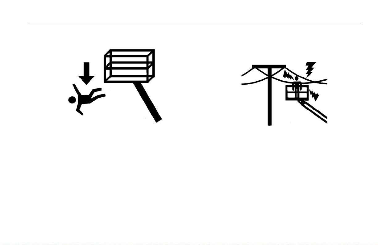
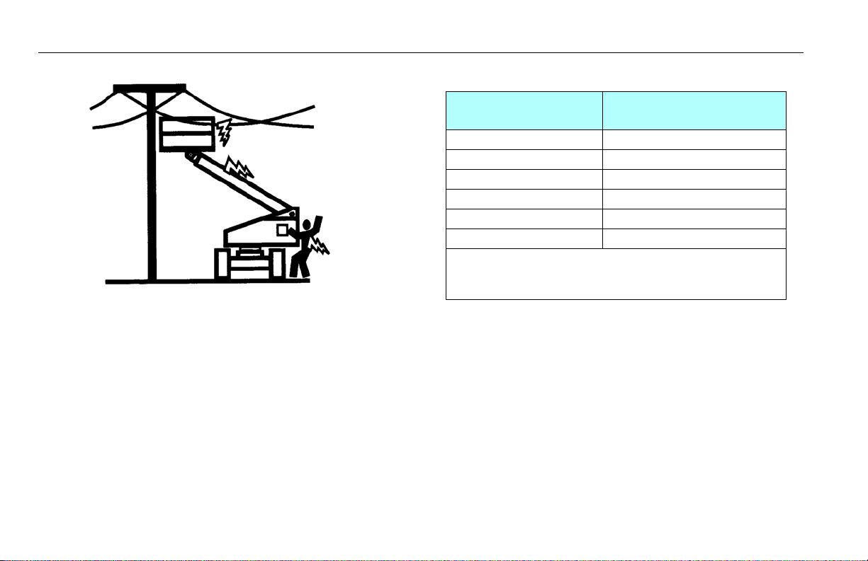
Electrocution Hazards
• This machine is not insulated and does not provide protection
from contact or proximity to electrical current.
3121216 – JLG Lift – 1-5
SECTION 1 - SAFETY PRECAUTIONS
Table 1-1. Minimum Approach Distances (M.A.D.)
• Maintain distance from electrical lines, apparatus, or any energized (exposed or insulated) parts according to the Minimum
Approach Distance (MAD) as shown in
• Allow for machine movement and electrical line swaying.
Tabl e 1-1 .
Voltage Range
(Phase to Phase)
0 to 50 KV 10 (3)
Over 50KV to 200 KV 15 (5)
Over 200 KV to 350 KV 20 (6)
Over 350 KV to 500 KV 25 (8)
Over 500 KV to 750 KV 35 (11)
Over 750 KV to 1000 KV 45 (14)
NOTE: This requirement shall apply except where
employer, local or governmental regulations are
more stringent.
• Maintain a clearance of at least 10 ft. (3m) between any part of
the machine and its occupants, their tools, and their equipment from any electrical line or apparatus carrying up to
50,000 volts. One foot additional clearance is required for
every additional 30,000 volts or less.
MINIMUM APPROACH DISTANCE
in Feet (Meters)
1-6 – JLG Lift – 3121216
SECTION 1 - SAFETY PRECAUTIONS
• The minimum approach distance may be reduced if insulating
barriers are installed to prevent contact, and the barriers are
rated for the voltage of the line being guarded. These barriers
shall not be part of (or attached to) the machine. The mini
mum approach distance shall be reduced to a distance within
the designed working dimensions of the insulating barrier.
This determination shall be made by a qualified person in
accordance with the employer, local, or governmental require
ments for work practices near energized equipment
DO NOT MANEUVER MACHINE OR PERSONNEL INSIDE PROHIBITED ZONE (MAD). ASSUME
ALL ELECTRICAL PARTS AND WIRING ARE ENERGIZED UNLESS KNOWN OTHERWISE.
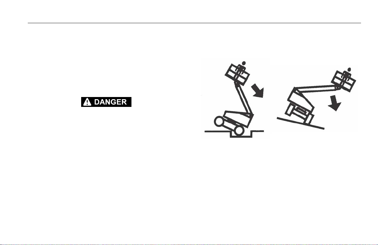
Tipping Hazards
• The user must be familiar with the surface before driving. Do
-
-
not exceed the allowable sideslope and grade while driving.
• Do not elevate platform or drive with platform elevated while
on or near a sloping, uneven, or soft surface. Ensure machine is
positioned on a firm, level and smooth surface before elevat
ing platform or driving with the platform in the elevated position.
• Before driving on floors, bridges, trucks, and other surfaces,
check allowable capacity of the surfaces.
-
3121216 – JLG Lift – 1-7

SECTION 1 - SAFETY PRECAUTIONS
• Never exceed the maximum work load as specified on the
platform. Keep all loads within the confines of the platform,
unless authorized by JLG.
• Keep the chassis of the machine a minimum of 2 ft. (0.6m)
from holes, bumps, drop-offs, obstructions, debris, concealed
holes, and other potential hazards at the ground level.
• Do not push or pull any object with the boom.
• Never attempt to use the machine as a crane. Do not tie-off
machine to any adjacent structure. Never attach wire, cable, or
any similar items to platform.
• Do not operate the machine when wind conditions exceed 28
mph (12.5 m/s). Refer to Table 1-2, Beaufort Scale (For Reference Only).
• Do not increase the surface area of the platform or the load.
Increase of the area exposed to the wind will decrease stability.
• Do not increase the platform size with unauthorized deck
extensions or attachments.
• If boom assembly or platform is in a position that one or more
wheels are off the ground, all persons must be removed before
attempting to stabilize the machine. Use cranes, forklift trucks,
or other appropriate equipment to stabilize machine.
1-8 – JLG Lift – 3121216
DO NOT OPERATE THE MACHINE WHEN WIND CONDITIONS EXCEED 28 MPH (12.5 M/S).
Table 1-2. Beaufort Scale (For Reference Only)
SECTION 1 - SAFETY PRECAUTIONS
Beaufort
Number
0 0 0-0.2 Calm Calm. Smoke rises vertically
1 1-3 0.3-1.5 Light air Wind motion visible in smoke
2 4-7 1.6-3.3 Light breeze Wind felt on exposed skin. Leaves rustle
3 8-12 3.4-5.4 Gentle breeze Leaves and smaller twigs in constant motion
4 13-18 5.5-7.9 Moderate breeze Dust and loose paper raised. Sm all branches begin to move.
5 19-24 8.0-10.7 Fresh breeze Smaller trees sway.
6 25-31 10.8-13.8 Strong breeze Large branches in motion. Flags waving near horizontal. Umbrella use
7 32-38 13.9-17.1 Near Gale/Moderate Gale Whole trees in motion. Effort needed to walk against the wind.
8 39-46 17.2-20.7 Fresh Gal e Twig s broken from trees. Cars veer on road.
9 47-54 20.8-24.4 Strong Gale Light structure damage.
Wind Speed
mph m/s
Description Land Conditions
becomes difficult.
3121216 – JLG Lift – 1-9
SECTION 1 - SAFETY PRECAUTIONS
Crushing and Collision Hazards
• Approved head gear must be worn by all operating and
ground personnel.
• Check work area for clearances overhead, on sides, and bottom of platform when lifting or lowering platform, and driving.
• During operation, keep all body parts inside platform railing.
• Use the boom functions, not the drive function, to position the
platform close to obstacles.
• Always post a lookout when driving in areas where vision is
obstructed.
• Keep non-operating personnel at least 6 ft. (1.8m) away from
machine during all driving and swing operations.
• Under all travel conditions, the operator must limit travel
speed according to conditions of ground surface, congestion,
visibility, slope, location of personnel, and other factors which
may cause collision or injury to personnel.
• Be aware of stopping distances in all drive speeds. When driving in high speed, switch to low speed before stopping. Travel
grades in low speed only.
• Do not use high speed drive in restricted or close quarters or
when driving in reverse.
• Exercise extreme caution at all times to prevent obstacles from
striking or interfering with operating controls and persons in
the platform.
• Be sure that operators of other overhead and floor level
machines are aware of the aerial work platform’s presence. Disconnect power to overhead cranes.
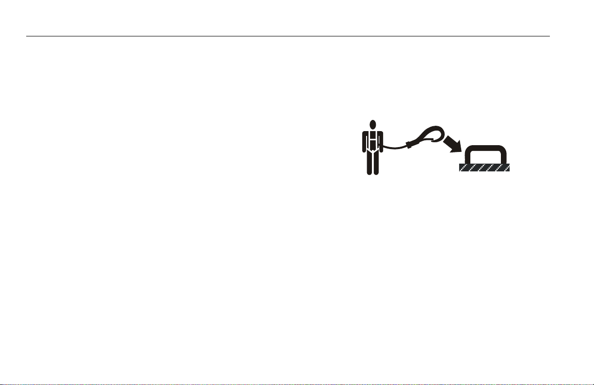
• Warn personnel not to work, stand, or walk under a raised
boom or platform. Position barricades on floor if necessary.
1-10 – JLG Lift – 3121216

SECTION 1 - SAFETY PRECAUTIONS
1.4 TOWING, LIFTING, AND HAULING
• Never allow personnel in platform while towing, lifting, or
hauling.
• This machine should not be towed, except in the event of
emergency, malfunction, power failure, or loading/unloading.
Refer to the Emergency Procedures section of this manual for
emergency towing procedures.
• Ensure boom is in the stowed position and the turntable
locked prior to towing, lifting or hauling. The platform must be
completely empty of tools.
• When lifting machine, lift only at designated areas of the
machine. Lift the unit with equipment of adequate capacity.
• Refer to the Machine Operation section of this manual for lifting information.
1.5 MAINTENANCE
This sub-section contains general safety precautions which must
be observed during maintenance of this machine. Additional pre
cautions to be observed during machine maintenance are
inserted at the appropriate points in this manual and in the Service and Maintenance Manual. It is of utmost importance that
maintenance personnel pay strict attention to these precautions
to avoid possible injury to personnel or damage to the machine
or property. A maintenance program must be established by a
qualified person and must be followed to ensure that the
machine is safe.
Maintenance Hazards
• Shut off power to all controls and ensure that all moving parts
are secured from inadvertent motion prior to performing any
adjustments or repairs.
• Never work under an elevated platform until it has been fully
lowered to the full down position, if possible, or otherwise
supported and restrained from movement with appropriate
safety props, blocking, or overhead supports.
• DO NOT attempt to repair or tighten any hydraulic hoses or fittings while the machine is powered on or when the hydraulic
system is under pressure.
• Always relieve hydraulic pressure from all hydraulic circuits
before loosening or removing hydraulic components.
-
3121216 – JLG Lift – 1-11
SECTION 1 - SAFETY PRECAUTIONS
• DO NOT use your hand to check for leaks. Use a piece of cardboard or paper to search for leaks. Wear gloves to help protect
hands from spraying fluid.
• Ensure replacement parts or components are identical or
equivalent to original parts or components.
• Never attempt to move heavy parts without the aid of a
mechanical device. Do not allow heavy objects to rest in an
unstable position. Ensure adequate support is provided when
raising components of the machine.
• Do not use machine as a ground for welding.
• When performing welding or metal cutting operations, precautions must be taken to protect the chassis from direct
exposure to weld and metal cutting spatter.
• Do not refuel the machine with the engine running.
• Use only approved non-flammable cleaning solvents.
• Do not replace items critical to stability, such as batteries or
solid tires, with items of different weight or specification. Do
not modify unit in any way to affect stability.
• Refer to the Service and Maintenance Manual for the weights
of critical stability items.
MODIFICATION OR ALTERATION OF AN AERIAL WORK PLATFORM SHALL BE MADE ONLY
WITH PRIOR WRITTEN PERMISSION FROM THE MANUFACTURER.
1-12 – JLG Lift – 3121216

Battery Hazards
SECTION 1 - SAFETY PRECAUTIONS
• Always disconnect batteries when servicing electrical components or when performing welding on the machine.
• Do not allow smoking, open flame, or sparks near battery during charging or servicing.
• Do not contact tools or other metal objects across the battery
terminals.
• Always wear hand, eye, and face protection when servicing
batteries. Ensure that battery acid does not come in contact
with skin or clothing.
BATTERY FLUID IS HIGHLY CORROSIVE. AVOID CONTACT WITH SKIN AND CLOTHING AT
ALL TIMES. IMMEDIATELY RINSE ANY CONTACTED AREA WITH CLEAN WATER AND SEEK
MEDICAL ATTENTION.
• Charge batteries only in a well ventilated area.
• Avoid overfilling the battery fluid level. Add distilled water to
batteries only after the batteries are fully charged.
3121216 – JLG Lift – 1-13

SECTION 1 - SAFETY PRECAUTIONS
NOTES:
1-14 – JLG Lift – 3121216

SECTION 2 - USER RESPONSIBILITIES, MACHINE PREPARATION, AND INSPECTION
SECTION 2. USER RESPONSIBILITIES, MACHINE PREPARATION, AND INSPECTION
2.1 PERSONNEL TRAINING
The aerial platform is a personnel handling device; so it is necessary that it be operated and maintained only by trained personnel.
Persons under the influence of drugs or alcohol or who are subject to seizures, dizziness or loss of physical control must not
operate this machine.
Operator Training
Operator training must cover:
1. Use and limitations of the controls in the platform and at
the ground, emergency controls and safety systems.
2. Control labels, instructions, and warnings on the machine.
3. Rules of the employer and government regulations.
4. Use of approved fall protection device.
5. Enough knowledge of the mechanical operation of the
machine to recognize a malfunction or potential malfunction.
6. The safest means to operate the machine where overhead
obstructions, other moving equipment, and obstacles,
depressions, holes, drop-offs.
7. Means to avoid the hazards of unprotected electrical conductors.
8. Specific job requirements or machine application.
Training Supervision
Training must be done under the supervision of a qualified person in an open area free of obstructions until the trainee has
developed the ability to safely control and operate the machine.
Operator Responsibility
The operator must be instructed that he/she has the responsibility and authority to shut down the machine in case of a malfunction or other unsafe condition of either the machine or the job
site.
3121216 – JLG Lift – 2-1

SECTION 2 - USER RESPONSIBILITIES, MACHINE PREPARATION, AND INSPECTION
2.2 PREPARATION, INSPECTION, AND MAINTENANCE
The following table covers the periodic machine inspections
and maintenance required by JLG Industries, Inc. Consult local
regulations for further requirements for aerial work platforms.
The frequency of inspections and maintenance must be
increased as necessary when the machine is used in a harsh or
hostile environment, if the machine is used with increased fre
quency, or if the machine is used in a severe manner.
JLG INDUSTRIES, INC. RECOGNIZES A FACTORY-TRAINED SERVICE TECHNICIAN AS A PERSON WHO HAS SUCCESSFULLY COMPLETED THE JLG SERVICE TRAINING SCHOOL FOR THE
SPECIFIC JLG PRODUCT MODEL.
-
2-2 – JLG Lift – 3121216

SECTION 2 - USER RESPONSIBILITIES, MACHINE PREPARATION, AND INSPECTION
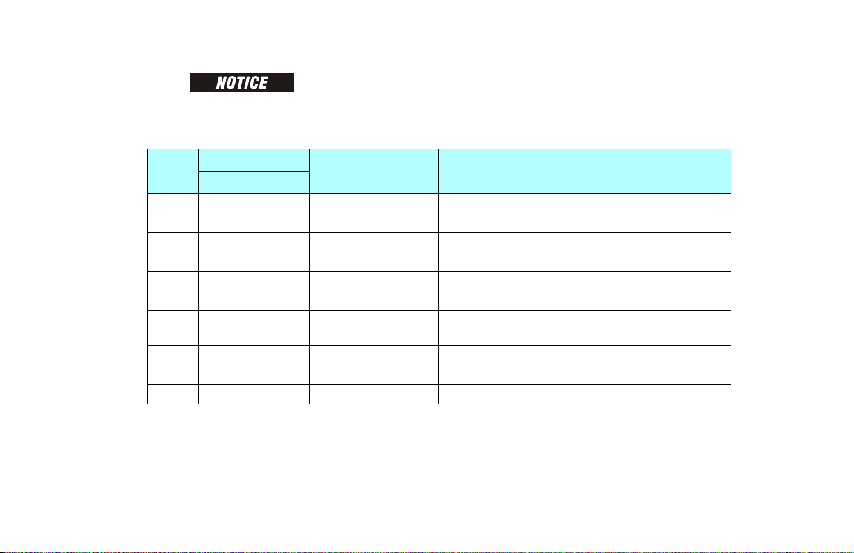
Table 2-1.Inspection and Maintenance Table
Type Frequenc y Primary Responsibility Service Qualification Reference
Pre-Start Inspection Before using each day; or
whenever there’s an Operator change.
Pre-Delivery Inspectio n (See
Note)
Frequent Inspection
(See Note)
Annual Machine Inspection
(See Note)
Preventative Maintenance At intervals as specified in the S ervice and Maintenance
NOTE: Inspection forms are available from JLG. Use the Service and Maintenance Manual to perform inspections.
Be f or e ea c h s a le , le a se , or r en t al d el i ve r y. Owner, Dealer, or User Q ualified JLG Mechanic Service and Maintenance Manual
In service for 3 months or 150 hours, whichever comes first;
o r
Out of service for a period of more than 3 months;
o r
Purchase d used.
An n ua l ly , n o la t er t ha n 13 m on t hs f ro m th e da te o f p r i or
inspection.
Manual.
User or Operator User or Operator Operator and Safety Manual
Owner, Dealer, or User Qualified JLG Mechanic Service and Maintenance Manual
Owner, Dealer, or User Factory-Qualified Service
Tec h ni c ia n
(Recommended)
Owner, Dealer, or User Qualified JLG Mechanic Service and Maintenance Manual
and applicable JLG inspection form
and applicable JLG inspection form
Service and Maintenance Manual
and applicable JLG inspection form
3121216 – JLG Lift – 2-3
SECTION 2 - USER RESPONSIBILITIES, MACHINE PREPARATION, AND INSPECTION
13
12
11
10
7
8
3
2
6
5
4
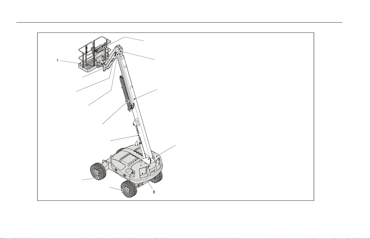
Figure 2-1. Basic Nomenclature
1. Platform
2. Jib (460SJ Only)
3. Jib Lift Cylinder (460SJ Only)
4. Level Cylinder
5. Power Track
6. Lift Cylinder
7. Drive Wheels
8. Steer Wheels
9. Ground Control
10. Turntable
11. B ase Boom
12. Fly B oom
13. Platform Console
2-4 – JLG Lift – 3121216

SECTION 2 - USER RESPONSIBILITIES, MACHINE PREPARATION, AND INSPECTION
Pre-Start Inspection
The Pre-Start Inspection should include each of the following:
1. Cleanliness – Check all surfaces for leakage (oil, fuel, or battery fluid) or foreign objects. Report any leakage to the
proper maintenance personnel.
2. Decals and Placards – Check all for cleanliness and legibility. Make sure none of the decals and placards are missing.
Make sure all illegible decals and placards are cleaned or
replaced.
3. Operation and Safety Manuals – Make sure a copy of the
Operator and Safety Manual, AEM Safety Manual (ANSI mar
kets only), and ANSI Manual of Responsibilities (ANSI markets only) is enclosed in the weather resistant storage
container.
4. “Walk-Around” Inspection – Refer to Figure 2-2. thru Figure 2-4.
5. Battery – Charge as required.
6. Fuel (Combustion Engine Powered Machines) – Add the
proper fuel as necessary.
7. Engine Oil Supply - Ensure the engine oil level is at the Full
mark on the dipstick and the filler cap is secure.
8. Hydraulic Oil – Check the hydraulic oil level. Ensure
hydraulic oil is added as required.
9. Accessories/Attachments - Reference the Operator and
Safety Manual of each attachment or accessory installed
upon the machine for specific inspection, operation, and
maintenance instructions.
10. Function Check – Once the “Walk-Around” Inspection is
complete, perform a functional check of all systems in an
area free of overhead and ground level obstructions. Refer
-
IF THE MACHINE DOES NOT OPERATE PROPERLY, TURN OFF THE MACHINE IMMEDIATELY! REPORT THE PROBLEM TO THE PROPER MAINTENANCE PERSONNEL. DO NOT
OPERATE THE MACHINE UNTIL IT IS DECLARED SAFE FOR OPERATION.
to Section 4 for more specific operating instructions.
3121216 – JLG Lift – 2-5

SECTION 2 - USER RESPONSIBILITIES, MACHINE PREPARATION, AND INSPECTION
Functional Check
First, using the ground controls, check all functions controlled
by the ground controls. Next, using the platform controls,
check all functions controlled by the platform controls.
1. Telescope boom IN and OUT several cycles at various
degrees of elevation lengths. Check for smooth telescope
operation.
2. Swing turntable to LEFT and RIGHT a minimum of 45
degrees. Check for smooth motion.
NOTE: Step 3 is only applicable for machines prior to S/N 0300140365.
3. Check the oscillating axle valve (if equipped) under the
turntable at the top front of frame. Observe that the valve
plunger is depressed when turntable is positioned forward,
and centered. Swing the turntable until bracket is past the
valve. The plunger should be fully extended.
NOTE: Step 4 is only applicable for machines prior to S/N 61718.
4. With the aid of an assistant to monitor the CHASSIS OUT OF
LEVEL indicator light on the platform control console, manually activate the indicator light by compressing any one of
the three tilt indicator mounting springs. If the light does
not illuminate, shut down machine and contact a qualified
service technician before continuing operation.
NOTE: Step 5 is applicable for machines built from S/N 61718 to present.
5. Check the chassis out of level indicator located on the platform control console by driving, with the machine in level
position, up a suitable ramp of at least 5° slope. Check the
out of level indicator, with the machine on the ramp. If the
light does not illuminate, return the machine to a level sur
face, shut down the machine, and contact a qualified technician before resuming operation.
6. Check that platform self-leveling system functions properly
during raising and lowering of boom.
7. Check rotator for smooth operation and assure platform
will rotate 90 degrees in both directions from centerline of
boom.
8. Drive forward and reverse; check for proper operation.
9. Check boom horizontal limit switches to see that they are
operable and not damaged. Raise and lower Boom. Check
for smooth operation.
NOTE: When the boom is raised above horizontal, high drive speed is
cut out.
10. Steer left and right; check for proper operation.
-
2-6 – JLG Lift – 3121216

SECTION 2 - USER RESPONSIBILITIES, MACHINE PREPARATION, AND INSPECTION
11. Footswitch.
FOOTSWITCH MUST BE ADJUSTED SO THAT FUNCTIONS WILL OPERATE WHEN PEDAL IS
APPROXIMATELY AT ITS CENTER OF TRAVEL. IF SWITCH OPERATES WITHIN LAST 1/4" OF
TRAVEL, TOP OR BOTTOM, IT SHOULD BE ADJUSTED.
a. Activate hydraulic system, by depressing footswitch.
Operate Telescope and hold control. Remove foot from
footswitch, motion should stop. If it does not, shut
down machine and contact a trained JLG service tech
nician.
b. With footswitch depressed, operate Lift and hold con-
trol. Remove foot from footswitch, motion should stop.
If it does not, shut down machine and contact a
trained JLG service technician.
c. With engine power shut down, depress the footswitch.
Attempt to start engine. Engine should not attempt to
start when footswitch is depressed. If starter engages or
engine turns over, shut down machine and contact a
trained JLG service technician.
12. Auxiliary Power.
Operate each function control switch (e.g. Tele, Lift, and
Swing) to ensure they function in both directions using
auxiliary power.
13. Ground Controls.
Place Ground/Platform Select switch to Ground. Start
engine. Platform controls should not operate.
-
3121216 – JLG Lift – 2-7

SECTION 2 - USER RESPONSIBILITIES, MACHINE PREPARATION, AND INSPECTION
Figure 2-2. Daily Walk-Around Inspection - Sheet 1 of 3
2-8 – JLG Lift – 3121216

SECTION 2 - USER RESPONSIBILITIES, MACHINE PREPARATION, AND INSPECTION
Walk-Around inspection
Begin the "Walk-Around Inspection" at Item 1, as noted on
the diagram. Continue to the right (counterclockwise viewed
from top) checking each item in sequence for the conditions
listed in the Walk-Around Inspection Checklist.
TO AVOID INJURY, BE SURE MACHINE POWER IS OFF.
DO NOT OPERATE MACHINE UNTIL ALL MALFUNCTIONS HAVE BEEN CORRECTED.
INSPECTION NOTE: On all components, make sure there are no
loose or missing parts, that they are securely fastened, and no visible damage, leaks or excessive wear exists in addition to any other
criteria mentioned.
1. Platform Assembly and Gate - Footswitch in good working
order, not modified, disabled or blocked.
2. Platform & Ground Control Consoles - Switches and levers
return to neutral, decals/placards secure and legible, control markings legible.
3. Rotator - See Inspection Note.
4. All Hydraulic Cylinders - No visible damage; pivot pins and
hydraulic hoses undamaged, not leaking.
5. Boom - See Inspection Note.
6. Drive Motor, Brake, and Hub - See Inspection Note.
7. Wheel/Tire Assembly -
No loose or missing lug nuts, proper
inflation (pneumatic). Inspect for worn tread, cuts, tears or
other discrepancies. Inspect wheels for damage and corrosion.
8. Turntable Bearing - Evidence of proper lubrication; no evidence of loose bolts or looseness between bearing or
structure.
9. Swing Drive - See Inspection Note.
10. Hood - See Inspection Note.
11. Control Valve - See Inspection Note.
12. Hydraulic Filter - See Inspection Note.
13. Hydraulic Oil Supply - Recommended oil level sight gauge.
(Check level with cold oil, systems shut down, machine in
stowed position) Cap in place and secure.
Figure 2-3. Daily Walk-Around Inspection - Sheet 2 of 3
3121216 – JLG Lift – 2-9

SECTION 2 - USER RESPONSIBILITIES, MACHINE PREPARATION, AND INSPECTION
14. Fuel Supply - Filler cap secure, no visible damage to the
tank or evidence of leaks.
NOTE: Lockout Valves were used prior to S/N 0300140365.
15. Oscillating Axle, Lockout Valves - See Inspection Note.
16. Tie Rod Ends and Steering Spindles - See Inspection Note.
17. Engine Air Filter - Element clean. See Inspection Note.
18. Engine Oil Supply - Full mark on dipstick; filler cap secure.
19. Muffler and Exhaust System - See Inspection Note.
20. Auxiliary Power Pump - See Inspection Note.
21. Hydraulic Pump - See Inspection Note.
22. Battery - Proper electrolyte levels; cables tight, no visible
damage or corrosion.
Figure 2-4. Daily Walk-Around Inspection - Sheet 3 of 3
2-10 – JLG Lift – 3121216

SECTION 2 - USER RESPONSIBILITIES, MACHINE PREPARATION, AND INSPECTION
2.3 OSCILLATING AXLE LOCKOUT TEST (IF EQUIPPED)
LOCKOUT SYSTEM TEST MUST BE PERFORMED QUARTERLY, ANY TIME A SYSTEM COMPONENT IS REPLACED, OR WHEN IMPROPER SYSTEM OPERATION IS SUSPEC TED.
NOTE: Ensure boom is fully retracted, lowered, and centered between
drive wheels prior to beginning lockout cylinder test.
1. Place a 6 inches (15.2 cm) high block with ascension ramp
in front of left front wheel.
2. From platform control station, start engine
3. Place DRIVE control lever to FORWARD position and care-
fully drive machine up ascension ramp until left front wheel
is on top of block.
4. Carefully activate SWING control lever and position boom
over right side of machine.
5. With boom over right side of machine, place DRIVE control
lever to REVERSE and drive machine off of block and ramp.
6. Have an assistant check to see that left front or right rear
wheel remains elevated in position off of ground.
7. Carefully activate SWING control lever and return boom to
stowed position (centered between drive wheels). When
boom reaches center, stowed position, lockout cylinders
should release and allow wheel to rest on ground, it may be
necessary activate DRIVE to release cylinders.
8. Place the 6 inches (15.2 cm) high block with ascension ramp
in front of right front wheel.
9. Place DRIVE control lever to FORWARD and carefully drive
machine up ascension ramp until right front wheel is on top
of block.
3121216 – JLG Lift – 2-11

SECTION 2 - USER RESPONSIBILITIES, MACHINE PREPARATION, AND INSPECTION
10. With boom over left side, place DRIVE control lever to
REVERSE and drive machine off block and ramp.
11. Have an assistant check to see that right front or left rear
wheel remains elevated in position off of ground.
12. Carefully activate SWING control lever and return boom to
stowed position (centered between drive wheels). When
boom reaches center, stowed position, lockout cylinders
should release and allow wheel to rest on ground, it may be
necessary activate DRIVE to release cylinders.
13. If lockout cylinders do not function properly, have qualified
personnel correct the malfunction prior to any further
operation.
2-12 – JLG Lift – 3121216

SECTION 3 - MACHINE CONTROLS AND INDICATORS
SECTION 3. MACHINE CONTROLS AND INDICATORS
3.1 GENERAL
THE MANUFACTURER HAS NO DIRECT CONTROL OVER MACHINE APPLICATION AND
OPERATION. THE USER AND OPERATOR ARE RESPONSIBLE FOR CONFORMING WITH
GOOD SAFETY PRACTICES.
This section provides the necessary information needed to
understand control functions.
3.2 CONTROLS AND INDICATORS
NOTE: All machines are equipped with control panels that use symbols to indicate control
functions. On ANSI machines refer to decal located on the control box guard in front of
the control box or by the ground controls for these symbols and the corresponding
functions.
NOTE: The indicator panels use different shaped symbols to alert the operator to different
types of operational situations that could arise. The meaning of those symbols are
explained below.
Indicates a potentially hazardous situation, which if
not corrected, could result in serious injury or death.
This indicator will be red.
Indicates an abnormal operating condition, which if
not corrected, may result in machine interruption or
damage. This indicator will be yellow.
Indicates important information regarding the o perating condition, i.e. procedures essential for safe operation. This indicator will be green with the exception of
the capacity indicator which will be green or yellow
depending upon platform position.
3121216 – JLG Lift – 3-1

SECTION 3 - MACHINE CONTROLS AND INDICATORS
Ground Controls
See Figure 3-1., Ground Control Station - S Models and Figure 3-2.,
Ground Control Station - SJ Models
PERFORM PRE-OPERATIONAL CHECKS AND INSPECTIONS
FROM THE GROUND CONTROL STATION. WHEN PERSONNEL ARE IN THE PLATFORM, OPERATION OF THE BOOM
WILL ONLY BE PERFORMED WITH THE PERMISSION OF THE
PLATFORM OCCUPANT(S).
NOTE: Engine Start/Auxiliary Power, Main Lift, Swing, Platform Level, Main Telescope, and
Platform Rotator control switches are spring-loaded and will automatically return to
neutral (off) when released.
TO AVOID SERIOUS INJURY, DO NOT OPERATE MACHINE IF ANY CONTROL LEVERS OR
TOGGLE SWITCHES CONTROLLING PLATFORM MOVEMENT DO NOT RETURN TO THE
OFF POSITION WHEN RELEASED.
NOTE: If equipped, the Function Enable switch must be held down in
order to operate Telescope, Swing, Lift, Jib Lift, Platform Level
Override, and Platform Rotate functions.
1. Platform Rotate
Permits rotation of the platform when positioned to the left
or right.
ONLY USE THE PLATFORM LEVELING OVERRIDE FUNCTION FOR SLIGHT LEVELING OF
THE PLATFORM. INCORRECT USE COULD CAUSE THE LOAD/OCCUPANTS TO SHIFT OR
FALL. FAILURE TO DO SO COULD RESULT IN DEATH OR SERIOUS INJURY.
2. Platform Leveling Override
A three position switch allows the operator to adjust the
automatic self leveling system. This switch is used to adjust
the platform level in situations such as ascending/descend
ing a grade.
3. Articulating Jib Boom (If Equipped)
Provides raising and lowering of the jib when positioned up
or down.
-
3-2 – JLG Lift – 3121216

Figure 3-1. Ground Control Station - S Models
1. Platform Rotate
2. Platform Leveling Override
3. Not Used
4. Power/Emergency Stop
5. Engine Start/Auxiliary Power
o r
En g in e St a r t/ A ux i li a r y P ow e r/ F un c ti o n E n ab l e
6. Boom Lift
7. Hourmeter
8. Platform/Ground Select Switch
9. Swing
10. Boom Telescope
SECTION 3 - MACHINE CONTROLS AND INDICATORS
3121216 – JLG Lift – 3-3

SECTION 3 - MACHINE CONTROLS AND INDICATORS
Figure 3-2. Ground Control Station - SJ Models
1. Platform Rotate
2. Platform Leveling Override
3. Articulating Jib Boom
4. Power/Emergency Stop
5. Engine Star t/Auxiliary Power
o r
En g in e S ta r t/ A ux i li a r y P ow e r/ F un c ti o n E n ab l e
6. Boom Lift
7. Hourmeter
8. Platform/Ground Select Switch
9. Swing
10. Boom Telescope
3-4 – JLG Lift – 3121216

WHEN THE MACHINE IS SHUT DOWN THE MASTER/EMERGENCY STOP SWITCH MUST
BE POSITIONED TO THE OFF POSITION TO PREVENT DRAINING THE BATTERY.
4. Power/Emergency Stop Switch
A two-position red mushroom shaped switch supplies
power to PLATFORM/GROUND SELECT switch when pulled
out (on). When pushed in (off), power is shut off to the
PLATFORM/GROUND SELECT switch.
NOTE: When Power/Emergency Stop switch is in the on position and engine is not running,
an alarm will sound, indicating Ignition is on.
SECTION 3 - MACHINE CONTROLS AND INDICATORS
5. Engine Start/Auxiliary Power Switch
or
Engine Start/ Auxiliary Power Switch /Function Enable
To start the engine, the switch must be held "UP"
until the engine starts.
To use auxiliary power, the switch must be held
“DOWN” for duration of auxiliary pump use. Aux
power can only be used if the engine is not running.
If equipped, the enable switch must be held
"DOWN" to enable all boom controls when the
engine is running.
NOTE: Auxiliary power only works if there is no oil pressure, and is disabled if engine is
running.
3121216 – JLG Lift – 3-5

SECTION 3 - MACHINE CONTROLS AND INDICATORS
WHEN OPERATING THE BOOM ENSURE THERE ARE NO PERSONNEL AROUND OR
UNDER PLATFORM.
6. Boom Lift Control
Provides raising and lowering of the boom when positioned up or down.
7. Hourmeter
Registers the amount of time the machine has been in use,
with the engine running. By connecting into the oil pressure circuit of the engine, only engine run hours are
recorded. The hourmeter registers up to 9,999.9 hours and
cannot be reset.
8. Platform/Ground Select Switch
Supplies power to the platform control console when positioned to PLATFORM. With the switch in GROUND position,
power is shut off to the platform control console, and only
the controls on the ground control panel are operable.
NOTE: With the Platform/Ground Select Switch in the center position, power is shut off to
controls at both operating stations. Remove the key to prevent the controls from
being actuated.
9. Swing Control
Provides 360 degrees non-continuous turntable rotation
when positioned to the right or left.
10. Main Telescope Control
Provides extension and retraction of the main boom, when
positioned to in or out.
3-6 – JLG Lift – 3121216

Ground Control Indicator Panel
1. Battery Charging
2. Engine Oil Pressure
3. Engine Coolant Temp
4. Engine Oil Temp
5. Engine Malfunction
6. Low Fuel
7. Glow Plug
8. Hyd. Filter Bypass
9. Trans Filter Bypass
10. Engine Air Filter Bypass
Figure 3-3. Ground Control Indicator Panel
(Prior to S/N 93233)
See Figure 3-3., Ground Control Indicator Panel (Prior to S/N 93233)
and Figure 3-4., Ground Control Indicator Panel (S/N 93233 to Present)
1. Battery Charging Indicator
Indicates a problem in the battery or charging circuit and
service is required.
2. Engine Oil Pressure Indicator
Indicates that engine oil pressure is below normal and service is required.
3. Engine Coolant Temperature (Ford and Isuzu) Indicator
Indicates that engine coolant temperature is abnormally
high and service is required.
SECTION 3 - MACHINE CONTROLS AND INDICATORS
3121216 – JLG Lift – 3-7

SECTION 3 - MACHINE CONTROLS AND INDICATORS
12
11
1. Battery Charging
2. Engine Oil Pressure
3. Engine Coolant Temp
4. Engine Oil Temp
5. Engine Malfunction
6. Low Fuel
7. Glow Plug
8. Not Used
9. Not Used
10. Not Used
11. Platform Overload CE Only
12. Drive and Steer Disable
Figure 3-4. Ground Control Indicator Panel
(S/N 93233 to Present)
4. Engine Oil Temperature Indicator (Deutz)
Indicates that the temperature of the engine oil, which also
serves as engine coolant, is abnormally high and service is
required.
5. Engine Malfunction Indicator (Ford Only, prior to S/N
61718)
If an electrical malfunction occurs, this light will illuminate
and stay lit until problem is eliminated. To find the specific
malfunction, use the test of the EFI diagnostics
Engine Con-
trol Module To show flash code of problem area.
6. Low Fuel Indicator
NOTE: Refer to Fuel Reser ve/Shut-Off System in Section 4 for detailed information.
Indicates fuel level is 1/8 full or less.
3-8 – JLG Lift – 3121216

SECTION 3 - MACHINE CONTROLS AND INDICATORS
7. Glow Plug Wait Indicator (Diesel)
Indicates the glow plugs are on. The glow plugs are automatically turned on with the ignition circuit and remain on
for approximately seven seconds. Start the engine only
after the light goes out.
8. Hydraulic Filter Bypass Indicator
Indicates that the return oil filter is too restrictive and needs
to be replaced.
9. Transmission Pump Oil Filter Indicator
Indicates that charge pump filter is too restrictive and
needs to be replaced. This indicator has an integral temperature sensor (70 degrees F.) so that false signals are not generated when the hydraulic oil is below normal operating
temperature.
10. Engine Air Filter Indicator
Indicates the air filter is too restrictive and needs to be
replaced.
11. Platform Overload (CE Only)
Indicates the platform has been overloaded.
12. Drive and Steer Disable Indicator (If equipped)
Indicates the Drive and Steer Disable function has been
activate
3121216 – JLG Lift – 3-9

SECTION 3 - MACHINE CONTROLS AND INDICATORS
Platform Station
See Figure 3-5., Platform Control Console and Figure 3-6., Platform
Control Console - w/Drive Orientation
When starting at platform, the Platform/Ground Switch, at the
ground control box be selected platform, and the large red
Power Stop Button be pulled out at platform and ground control.
TO AVOID SERIOUS INJURY, DO NOT OPERATE MACHINE IF ANY CONTROL LEVERS OR
TOGGLE SWITCHES CONTROLLING PLATFORM MOVEMENT DO NOT RETURN TO THE
OFF OR NEUTRAL POSITION WHEN RELEASED.
1. Drive Speed Switch/Torque Select
The switch has three positions. The forward position gives
maximum drive speed. The back position gives maximum
torque for rough terrain and climbing grades. The center
position allows the machine to be driven as quietly as pos
sible by leaving the engine at mid speed and the drive
motors in maximum displacement.
ONLY USE THE PLATFORM LEVELING OVERRIDE FUNCTION FOR SLIGHT LEVELING OF
THE PLATFORM. INCORRECT USE COULD CAUSE THE LOAD/OCCUPANTS TO SHIFT OR
FALL. FAILURE TO DO SO COULD RESULT IN DEATH OR SERIOUS INJURY.
2. Platform Leveling Override
A three position switch allows the operator to adjust the
automatic self leveling system. This switch is used to adjust
the platform level in situations such as ascending/descend
ing a grade.
3. Horn
Supplies electrical power to an audible warning device
when pressed.
4. Power/Emergency Stop
An on-off Power/Emergency Stop switch and a separate
-
Engine Start/Auxiliary Power toggle switch on the platform
console supply electrical power to the starter solenoid,
when the ignition switch is placed in the ON position and
the ENGINE START switch is push forward.
-
3-10 – JLG Lift – 3121216

SECTION 3 - MACHINE CONTROLS AND INDICATORS
12
3
4
56
7
8910111213
1. Drive Speed/Torque Select
2. Platform Leveling Override
3. Horn
4. Power/Emergency Stop
5. Auxiliary Power
6. Fuel Select
7. Lights
8. Drive Steer
9. Main Telescope Control
10. J ib Lift
11. Platform Rotate
12. Func tion Speed
13. Main Lift/Swing
14. Footswitch (Not Shown)
Figure 3-5. Platform Control Console
3121216 – JLG Lift – 3-11

SECTION 3 - MACHINE CONTROLS AND INDICATORS
1001107677 A
1705170 A
1702938
12
3
4
56
15
89
7
1011 17 161213
1. Drive Speed/Torque Select
2. Platform Leveling Override
3. Horn
4. Power/Emergency Stop
5. Auxiliary Power
6. Fuel Select
7. Lights
8. Drive Steer
9. Main Telescope Control
10. Jib Lift
11. Platform Rotate
12. Function Speed
13. Main Lift/Swing
14. Footswitch (Not Shown)
15. Drive Or ientation Override
16. Sof t Touch Override
17. Soft Touch Indicator
Figure 3-6. Platform Control Console - w/Drive Orientation
3-12 – JLG Lift – 3121216

SECTION 3 - MACHINE CONTROLS AND INDICATORS
5. Auxiliary Power
Energizes the electrically operated pump, when actuated.
(Switch must be held ON for duration of auxiliary pump
use.)
The auxiliary pump functions to provide sufficient oil flow
to operate the basic machine functions should the main
pump or engine fail. The auxiliary pump will operate tower
boom lift, tower telescope, main boom lift, main telescope
and swing.
It should be noted that the functions will operate at a
slower than normal rate because of the lower gpm delivered.
WHEN OPERATING ON AUXILIARY POWER, DO NOT OPERATE MORE THAN ONE FUNCTION AT THE SAME TIME. SIMULTANEOUS OPERATION CAN OVERLOAD THE AUXILIARY PUMP MOTOR.
NOTE: The main function of auxiliary power is to lower the platform in the event of primary
power failure. Determine the reason for primary power failure and have the problem
corrected by a certified JLG service technician.
6. Fuel Select (Dual Fuel Engine Only) (If Equipped)
Gasoline or liquid propane fuel may be selected by moving
the switch to the appropriate position. It is unnecessary to
purge the fuel system before switching fuels, so there is no
waiting period when switching fuels while the engine is
running.
7. Lights (If Equipped)
Operates control console panel lights and head lights if the
machine is so equipped. The ignition switch does not have
to be on to operate the lights, so care must be taken to
avoid draining the battery if left unattended. The master
switch and / or the ignition switch at the ground control
will turn off power to all lights.
3121216 – JLG Lift – 3-13

SECTION 3 - MACHINE CONTROLS AND INDICATORS
8. Drive/Steer
Provides for driving either forward or backward. Push forward to drive forward, pull back to drive in reverse.
Steering is controlled by a thumb-activated rocker switch
on top of the joystick.
NOTE: Both drive and steer functions work in the opposite direction when the boom is posi-
tioned over front of the chassis.
9. Main Telescope Control
Allows extension and retraction of the main boom when
positioned to in or out.
10. Articulating Jib Lift (460SJ Only)
Push level, toggle switch forward to lift up, pull back to lift
down.
11. Platform Rotate
Allows the operator to rotate the basket to the left or right
when positioned to the desired direction.
DO NOT OPERATE MACHINE IF DRIVE SPEED/TORQUE SELECT OR FUNCTION SPEED
SWITCHES OPERATE WHEN BOOM IS ABOVE HORIZONTAL.
12. Function Speed
Provides variable speed control of all boom functions
grouped to the right of the knob. For smoothest operation of
these functions, use two hands: rotate the knob counterclockwise to the slowest position, select the function switch,
and while holding the switch on, rotate the knob to the
desired speed. To achieve a smooth stop, rotate the knob
ccw to a slow speed prior to letting go of the function switch.
Rotating the knob fully counterclockwise until a click is heard
puts all controls, including drive, main lift, and swing into
creep speed. This slow speed is used for fine positioning of
the platform when close to obstacles. A snail symbol is used
to indicate “creep” speed and is shown at the Function Speed
knob as well as near the proportional controllers to act as a
reminder.
3-14 – JLG Lift – 3121216

SECTION 3 - MACHINE CONTROLS AND INDICATORS
NOTE: When boom is positioned above horizontal and any of the following switches, Drive
Speed/torque Select or Function Speed, are positioned to High, high function speeds
are automatically cut out and the machine continues to operate at a lower speed.
13. Main Lift/Swing Controller
The dual axis joystick is provided for main lift and swing.
Push forward to lift up, pull backward to lift down. Move
right to swing right, move left to swing left. Moving the joystick activates switches to provide the functions selected.
Proportional control of these functions can be attained by
using the Function Speed knob.
NOTE: Main Lift, Swing, and Drive control levers are spring-loaded and will automatically
retur n to neut ral (off ) pos ition wh en relea sed.
NOTE: Main lift and swing functions may be selected in combination. The handle features a
round gate so that maximum speed is reduced when multiple functions are selected.
14. Footswitch (Not Shown)
This feature makes it necessary to depress the footswitch to
allow operation of the platform controls.
TO AVOID SERIOUS INJURY, DO NOT REMOVE, MODIFY OR DISABLE THE FOOTSWITCH
BY BLOCKING OR ANY OTHER MEANS.
FOOTSWITCH MUST BE ADJUSTED SO THAT FUNCTIONS WILL OPERATE WHEN PEDAL
IS APPROXIMATELY AT ITS CENTER OF TRAVEL. IF SWITCH OPERATES WITHIN LAST 1/
4" OF TRAVEL, TOP OR BOTTOM, IT SHOULD BE ADJUSTED.
NOTE: For engine starting, the footswitch must be in the released (up) position. Footswitch
must be actuated in order for the platform controls to function.
NOTE: These machines have a 7 second delay timer. If function has not been activated
within 7 seconds after depressing the footswitch, recycle footswitch.
3121216 – JLG Lift – 3-15

SECTION 3 - MACHINE CONTROLS AND INDICATORS
15. Drive Orientation Override
When the boom is swung over the rear tires or further in
either direction, the Drive Orientation indicator will illumi
nate when the drive function is selected. Push and release
the switch, and within 3 seconds move the Drive/Steer control to activate drive or steer. Before driving, locate the
black/white orientation arrows on both the chassis and the
platform controls. Move the drive controls in a direction
matching the directional arrows.
16. Soft Touch Override Switch (If equipped)
Enables the functions that were cut out by the Soft Touch
system to operate again at creep speed, allowing the operator to move the platform away from the obstacle that
caused the shutdown situation.
17. Soft Touch Indicator (If Equipped)
Indicates the Soft Touch bumper is against an object. All
controls are cut out until the override button is pushed, at
which time controls are active in the Creep Mode.
Platform Control Indicator Panel
(See Figure 3-7., Platform Control Indicator Panel) and Figure 3-8., Plat-
-
form Control Indicator Panel - w/Drive Orientation.
1. Tilt Alarm Warning Light and Alarm
This orange illuminator indicates that the chassis is on a
slope. An alarm will also sound when the chassis is on a
slope and the boom is above horizontal. If lit when boom is
raised or extended, retract and lower to below horizontal
then reposition machine so that it is level before continuing
operation. If the boom is above horizontal and the machine
is on a slope, the tilt alarm warning light will illuminate and
an alarm will sound and CREEP is automatically activated.
IF TILT WARNING LIGHT IS ILLUMINATED WHEN BOOM IS RAISED OR EXTENDED,
RETRACT AND LOWER TO BELOW HORIZONTAL THEN REPOSITION MACHINE SO THAT
IT IS LEVEL BEFORE EXTENDING BOOM OR RAISING BOOM ABOVE HORIZONTAL.
2. Platform Overload (If equipped)
Indicates the platform has been overloaded.
3-16 – JLG Lift – 3121216

SECTION 3 - MACHINE CONTROLS AND INDICATORS
1. Tilt
2. Platform Overload
3. Capacity
4. Fuel Level
5. Enable
6. Glow Plug
7. Malfunction
8. Generator
9. Soft Touch
10. Creep Speed
Figure 3-7. Platform Control Indicator Panel
1001107849 B
6
7
8
11
1
10
2
3
5
4
1. Tilt
2. Platform Overload
3. Capacity
4. Fuel Level
5. Enable
6. Glow Plug
7. Malfunction
8. Generator
9. Not Used
10. Creep Speed
11. Dri ve Orientation
Figure 3-8. Platform Control Indicator Panel -
w/Drive Orientation
3121216 – JLG Lift – 3-17

SECTION 3 - MACHINE CONTROLS AND INDICATORS
FULL TANK
3/4 TANK
1/4 TANK
LOW F UEL
(FLASHES ONCE
PER SECOND)
1/2 TANK
EMPTY
(FLASHES TEN
TIMES
PER SECOND)
Figure 3-9. Fuel Indicator
3. Capacity Indicator
Indicates the maximum capacity for the current position of
the platform.
4. Fuel Level Indicator
NOTE: Refer to Fuel Reser ve/Shut-Off System in Section 4 for detailed information.
Shows fuel level in tank and provides visual low fuel alarms.
3-18 – JLG Lift – 3121216

SECTION 3 - MACHINE CONTROLS AND INDICATORS
5. Enable Indicator
Indicates that the footswitch is depressed and the platform
controls are ready for use. To enable the controls, depress
the footswitch and select any function within seven sec
onds. The controls will then remain active as long as there is
not a delay of seven seconds between stopping one func
tion and starting the next one. If the seven second interval
is exceeded, the enable light will go out and the controls
will not operate. To enable the controls again, remove your
foot from the footswitch and depress the footswitch.
6. Glow Plug Indicator
Illuminates when the glow plugs are operating. Wait until
the light goes out before cranking engine.
7. Malfunction Indicator
On machines prior to S/N 61718, the light turns on and an
alarm sounds when machine’s power system requires
-
-
immediate service. Any of the following conditions will turn
on light and alarm: low engine oil pressure, high engine
coolant temperature, clogged engine air filter, low alterna
tor output, clogged hydraulic oil return filter, or clogged
charge pump filter.
On machines from S/N 61718 to present, the light indicates
that the Control System has detected a malfunction and a
Diagnostic Trouble Code has been set in the system mem
ory. Refer to the Service Manual for instructions concerning
the trouble codes and trouble code retrieval.
The malfunction indicator light will illuminate for 2-3 seconds when the key is positioned to the on position to act as
a self test.
-
-
3121216 – JLG Lift – 3-19

SECTION 3 - MACHINE CONTROLS AND INDICATORS
8. AC Generator (If Equipped)
When illuminated (Green), indicates the generator is in
operation.
9. Soft Touch Indicator (If Equipped)
When illuminated (Yellow), indicates the Soft Touch bumper is against an object. All controls are cut out until the
override button is pushed, at which time controls are active
in the Creep mode.
10. Creep Speed Indicator
Illuminated (Green) when the Function Speed Control is
turned to the creep position, the indicator acts as a
reminder that all functions are set to the slowest speed.
11. Drive Orientation Indicator
When the boom is swung beyond the rear drive tires or further in either direction, the Drive Orientation indicator will
illuminate when the drive function is selected. This is a signal for the operator to verify that the drive control is being
operated in the proper direction (i.e. controls reversed situ
ations).
-
3-20 – JLG Lift – 3121216

SECTION 4. MACHINE OPERATION
SECTION 4 - MACHINE OPERATION
4.1 DESCRIPTION
This machine is a self-propelled hydraulic personnel lift
equipped with a work platform on the end of an elevating and
rotating boom.
The primary operator control station is in the platform. From
this control station, the operator can drive and steer the
machine in both forward and reverse directions. The operator
can raise or lower the main or tower boom or swing the boom
to the left or right. Standard boom swing is 360 degree contin
uous left and right of the stowed position. The machine has a
Ground Control Station which will override the Platform Control Station. Ground Controls operate Boom Lift and Swing,
and are to be used in an emergency to lower the platform to
the ground should the operator in the platform be unable to
do so.
4.2 OPERATING CHARACTERISTICS AND LIMITATIONS
Capacities
Raising boom above horizontal and/or extension of boom
beyond retracted position with or without any load in platform, is based on the following criteria:
1. Machine is positioned on a smooth, firm and level surface.
-
2. Load is within manufacturer’s rated design capacity.
3. All machine systems are functioning properly.
4. Proper tire pressure exists in the tires.
5. Machine is as originally equipped from JLG.
3121216 – JLG Lift – 4-1

SECTION 4 - MACHINE OPERATION
Figure 4-1. Position Of Least Backward Stability
ROTATE PLATFORM
90 DEGREES
BOOM FULLY
ELEVATED AND
FULLY RETRACTED
MACHINE WILL TIP
OVER IN THIS DIRECTION IF
OVERLOADED OR OPERATED ON
AN OUT-OF-LEVEL
SURFACE
Stability
This machine as originally manufactured by JLG Industries Inc.,
when operated within its rated capacity on a smooth, firm and
level supporting surface, and in accordance with the instruc
tions provided on the machine and this manual, provides a
stable machine for all platform positions.
Machine stability is based on two positions which are called
FORWARD STABILITY and BACKWARD STABILITY. The machines
position of least backward stability is shown in
its position of least forward stability is shown in Figure 4-2.
TO AVOID FORWARD OR BACKWARD UPSET, DO NOT OVERLOAD MACHINE OR OPERATE
ON AN OUT-OF-LEVEL SURFACE.
Figure 4-1., and
-
4-2 – JLG Lift – 3121216

SECTION 4 - MACHINE OPERATION
TELESCOPE
FULL Y EX TENDED
BOOM
HORIZONTA L
Figure 4-2. Position Of Least Forward Stability
BOOM
HORIZONTAL
MACHINE WILL TIP OVER IN
THIS DIRECTION IF OVERLOADED OR
OPERATED ON AN OUT-OF-LEVEL SURFACE
TELESCOPE
FULLY EXTENDED
3121216 – JLG Lift – 4-3

SECTION 4 - MACHINE OPERATION
4.3 ENGINE OPERATION
NOTE: Initial starting should always be performed from the Ground
Control station.
Starting Procedure
1. Check engine oil. If necessary, add oil in accordance with
the Engine Manufacturer’s manual.
2. Check fuel level. Add fuel if necessary.
3. Check that air cleaner components are in place and
securely fastened.
IF ENGINE FAILS TO START PROMPTLY, DO NOT CRANK FOR AN EXTENDED PERIOD.
SHOULD ENGINE FAIL TO START ONCE AGAIN, ALLOW STARTER TO "COOL OFF" FOR 2-3
MINUTES. IF ENGINE FAILS AFTER SEVERAL ATTEMPTS, REFER TO ENGINE MAINTENANCE
MANUAL.
NOTE: Machines with diesel engines, after turning on ignition, opera-
tor must wait until glow plug indicator light goes out before
cranking engine.
4. Turn key of SELECT switch to GROUND. Position POWER/
EMERGENCY STOP switch to ON, then push the ENGINE
START switch to the upward position until engine starts.
ALLOW ENGINE TO WARM-UP FOR A FEW MINUTES AT LOW SPEED BEFORE APPLYING
ANY LOAD.
5. After engine has had sufficient time to warm up, shut
engine off.
4-4 – JLG Lift – 3121216

SECTION 4 - MACHINE OPERATION
6. Turn key of SELECT switch to PLATFORM.
7. From Platform position POWER/EMERGENCY STOP switch
to ON, then push the ENGINE START switch to the forward
position until engine starts.
NOTE: Footswitch must be in released (up) position before starter will
operate. If starter operates with footswitch in the depressed
position, DO NOT OPERATE MACHINE.
Shutdown Procedure
IF AN ENGINE MALFUNCTION NECESSITATES UNSCHEDULED SHUTDOWN, DETERMINE
AND CORRECT CAUSE BEFORE RESUMING ANY OPERATION.
1. Remove all load and allow engine to operate at low speed
setting for 3-5 minutes; this allows for further reduction of
internal engine temperature.
2. Position POWER/EMERGENCY STOP switch to OFF.
3. Turn key of MASTER switch to OFF position.
NOTE: Refer to Engine Manufacturer’s manual for detailed informa-
tion.
3121216 – JLG Lift – 4-5

SECTION 4 - MACHINE OPERATION
Fuel Reserve / Shut-Off System
NOTE: Reference the Service and Maintenance Manual along with a
qualified JLG Mechanic to verify your machine setup.
The Fuel Shutoff System monitors fuel and
senses when fuel level is getting low. The JLG
Control System automatically shuts the engine
down before the fuel tank is emptied unless
the machine is set up for Engine Restart.
If fuel level reaches the Empty range the ¼
tank indicator will flash once a second and
there will be approximately 5 minutes of
engine run time left. If the system is in this con
dition and automatically shuts down the engine, or the engine is
manually shut down before the 5 minute run time is complete,
the ¼ tank indicator will flash 10 times a second and the engine
will react according to machine setup. Setup options are as fol
lows:
-
• Engine One Restart - When the engine shuts down, the
operator will be permitted to cycle power and restart the
engine once with approximately 2 minutes of run time.
After the 2 minute run time is complete or if the engine is
shut down by the operator prior to the completion of the
2 minute run time, it cannot be restarted until fuel is
added to the tank.
• Engine Restart - When the engine shuts down, the operator will be permitted to cycle power and restart the
engine for approximately 2 minutes of run time. After the
2 minutes of run time is complete, the operator may cycle
power and restart the engine for an additional 2 minutes
of run time. The operator can repeat this process until
there is no more fuel available.
• Engine Stop - The engine will shut down. No restarts will
be permitted until fuel is added to the tank.
-
4-6 – JLG Lift – 3121216

4.4 TRAVELING (DRIVING)
SECTION 4 - MACHINE OPERATION
See Figure 4-3., Grades and Sideslopes
DO NOT DRIVE WITH BOOM EXTENDED OR ABOVE HORIZONTAL EXCEPT ON A SMOOTH,
FIRM AND LEVEL SURFACE.
DO NOT DRIVE WITH HOODS RAISED OR UNLATCHED.
TO AVOID LOSS OF TRAVEL CONTROL OR UPSET ON GRADES AND SIDESLOPES, DO NOT
DRIVE MACHINE ON GRADES OR SIDESLOPES EXCEEDING THOSE SPECIFIED ON MACHINE
INFORMATION PLACARD ON THE LEFT SIDE OF THE FRAME.
TRAVEL GRADES WITH DRIVE SPEED/TORQUE SELECT SWITCH IN THE FORWARD POSITION. USE EXTREME CAUTION WHEN DRIVING IN REVERSE AND AT ALL TIMES WHEN
DRIVING WITH PLATFORM ELEVATED AND ESPECIALLY WHEN DRIVING WITH ANY PART
OF MACHINE WITHIN 6 FEET (2 M) OF AN OBSTRUCTION. DO NOT USE DRIVE TO MANEU
VER PLATFORM CLOSE TO AN OBSTRUCTION...USE ONE OF THE BOOM FUNCTIONS.
BEFORE DRIVING, LOCATE THE BLACK/WHITE ORIENTATION ARROWS ON BOTH THE
CHASSIS AND THE PLATFORM CONTROLS. MOVE THE DRIVE CONTROLS IN A DIRECTION
MATCHING THE DIRECTIONAL ARROWS.
Traveling is limited by two factors:
1. Gradeability, which is the percent of grade of the incline the
machine can climb.
-
2. Sideslope, which is the angle of the slope the machine can
be driven across.
When the boom is raised or extended, the machine should not
be operated on grades or sideslopes that are greater than that
detected by the tilt alarm. The tilt alarm will sound to alert the
operator when the machine is on an unsafe slope. The
machines high drive function will also be cut back to low drive.
3121216 – JLG Lift – 4-7

SECTION 4 - MACHINE OPERATION
Figure 4-3. Grades and Sideslopes
DO NOT DRIVE MACHINE ON GRADES EXCEEDING THOSE SPECIFIED
ON MANUFACTURER’S NAMEPLATE
G
R
A
DE
S
I
D
E
S
L
O
P
E
LEVEL
4-8 – JLG Lift – 3121216

SECTION 4 - MACHINE OPERATION
Traveling Forward or Reverse
1. With engine running, depress footswitch and position
DRIVE control to FORWARD and hold for the duration of for
ward travel desired.
NOTE: When DRIVE or STEER functions are being operated there is an
interlock which prevents operation of boom functions.
2. Depress footswitch and position DRIVE control to REVERSE
and hold for duration of reverse travel desired.
3. Depress footswitch and position STEER control to RIGHT for
traveling right and LEFT for traveling left.
4. To obtain maximum travel speed, position the DRIVE controller to FAST and activate the following switches:
Position DRIVE SPEED/TORQUE SELECT switch to FAST. (Forward Position)
5. Prior to stopping the machine, position switches as follows:
Position DRIVE SPEED/TORQUE SELECT switch to LOW.
(Backward Position)
6. For traveling up grades, position switches as follows:
Position DRIVE SPEED/TORQUE SELECT switch to HIGH.
NOTE: For smoother operation when driving with fully extended
-
boom, place DRIVE control to SLOW before stopping.
This machine is equipped with a Drive Orientation Indicator. The
yellow light on the platform control console indicates that the
boom is swung beyond the rear drive tires and the machine may
Drive/Steer in the opposite direction from the movement of the
controls. If the indicator is illuminated, operate the Drive func
tion in the following manner:
1. Match the black and white direction arrows on both platform control panel and the chassis to determine the direction the machine will travel.
2. Push and release the Drive Orientation Override switch.
Within 3 seconds, slowly move the Drive control toward the
arrow matching the intended direction of machine travel.
The indicator light will flash during the 3 second interval
until the drive function is selected.
-
3121216 – JLG Lift – 4-9

SECTION 4 - MACHINE OPERATION
4.5 STEERING
Depress footswitch to steer machine, push on the left side of
the switch to steer left, on the right side to steer right.
BEFORE OPERATING MACHINE, MAKE SURE BOOM IS POSITIONED OVER REAR AXLE. IF
BOOM IS OVER FRONT AXLE (STEER WHEELS), STEER AND DRIVE CONTROLS WILL MOVE
IN OPPOSITE DIRECTION THAN INDICATED ON MACHINE PLACARDS.
4.6 PARKING AND STOWING
Park and stow machine as follows:
1. Park machine in travel position; boom lowered over rear, all
access panels and doors closed and secured, ignition off.
2. Check that brakes hold machine in position.
3. Chock wheels front and rear.
4. Turn off SELECT switch and remove key.
4.7 PLATFORM
Loading from Ground Level
1. Position chassis on a smooth, firm and level surface.
2. If total load (personnel, tools, and supplies) is less than
rated capacity, distribute load uniformly on platform floor,
and proceed to work position.
Loading From Positions Above Ground Level
Before loading weight to platform above ground level:
1. Determine what the total rated capacity weight will be after
additional weight is loaded (personnel, tools and supplies).
2. If total weight in platform will be less then rated capacity,
proceed with adding weight.
4-10 – JLG Lift – 3121216

SECTION 4 - MACHINE OPERATION
Platform Level Adjustment
ONLY USE THE PLATFORM LEVELING OVERRIDE FUNCTION FOR SLIGHT LEVELING OF THE
PLATFORM. INCORRECT USE COULD CAUSE THE LOAD/OCCUPANTS TO SHIFT OR FALL.
FAILURE TO DO SO COULD RESULT IN DEATH OR SERIOUS INJURY.
This switch is used to adjust the platform level in situations such
as ascending/descending a grade. To Level Up or Down - Posi
tion the Platform/Level control switch Up or Down and hold
until the platform is level.
Platform Rotation
1. Depress footswitch to rotate platform to the left, PLATFORM ROTATE control is positioned to the LEFT and held
until desired position is reached.
2. Depress footswitch to rotate platform to the right, PLATFORM ROTATE control is positioned to the RIGHT and held
until desired position is reached.
4.8 BOOM
A TILT WARNING LIGHT IS LOCATED ON THE CONTROL CONSOLE WHICH LIGHTS WHEN
THE CHASSIS IS ON A 5 DEGREE OR GREATER SLOPE. DO NOT SWING OR RAISE BOOM
ABOVE HORIZONTAL WHEN LIGHT IS LIT.
DO NOT DEPEND ON TILT ALARM AS A LEVEL INDICATOR FOR THE CHASSIS. THE TILT
ALARM INDICATES THE CHASSIS IS ON A SEVERE SLOPE (5 DEGREE OR GREATER). CHAS-
-
SIS MUST BE LEVEL BEFORE SWINGING, OR RAISING BOOM ABOVE HORIZONTAL.
TO AVOID MACHINE UPSET IF THE TILT WARNING LIGHT ILLUMINATED WHEN THE BOOM
IS RAISED ABOVE HORIZONTAL, LOWER THE PLATFORM TO GROUND LEVEL, THEN REPOSITION MACHINE SO THAT CHASSIS IS LEVEL BEFORE RAISING BOOM.
TRAVELING WITH BOOM BELOW HORIZONTAL IS PERMITTED ON GRADES AND SIDE
SLOPES SPECIFIED ON SERIAL NUMBER PLACARD.
TO AVOID SERIOUS INJURY, DO NOT OPERATE MACHINERY IF ANY CONTROL LEVER OR
TOGGLE SWITCH CONTROLLING PLATFORM MOVEMENT DOES NOT RETURN TO THE "OFF"
POSITION WHEN RELEASED.
3121216 – JLG Lift – 4-11

SECTION 4 - MACHINE OPERATION
TO AVOID A COLLISION AND INJURY IF PLATFORM DOES NOT STOP WHEN A CONTROL
SWITCH OR LEVER IS RELEASED, REMOVE FOOT FROM FOOTSWITCH OR USE EMERGENCY
STOP SWITCH TO STOP MACHINE.
Swinging the Boom
Depress footswitch to swing boom, with footswitch activated,
position SWING control switch to RIGHT or LEFT for direction
desired.
WHEN SWINGING THE BOOM MAKE SURE THERE IS AMPLE ROOM FOR THE BOOM TO
CLEAR SURROUNDING WALLS, PARTITIONS AND EQUIPMENT.
Raising and Lowering the Main Boom
NOTE: Lift up will not function when the boom is near full elevation
and the platform is out of level.
To raise or lower the Main Boom, with footswitch activated,
position Main Boom Lift lever to UP or DOWN until desired
height is reached.
Telescoping the Main Boom
To extend or retract the main boom, with the footswitch activated, position the Main Telescope Control Switch to the in or
out position and hold until the platform reaches the desired
position.
4-12 – JLG Lift – 3121216

SECTION 4 - MACHINE OPERATION
4.9 AUXILIARY POWER - NON ADE EQUIPPED MACHINES
WHEN OPERATING ON AUXILIARY POWER, DO NOT OPERATE MORE THAN ONE FUNCTION
AT A TIME. (SIMULTANEOUS OPERATION CAN OVERLOAD THE 12-VOLT AUXILIARY PUMP
MOTOR.)
A toggle type auxiliary power control switch is located on the
platform control station and another is located on the ground
control station. Operation of either switch turns on the electrically driven auxiliary hydraulic pump. This should be used in
case of failure of the main power plant. The auxiliary pump will
operate boom lift, telescope and swing. To activate auxiliary
power:
Activating from the Platform Control Station
1. Position PLATFORM/GROUND SELECT KEY SWITCH to PLATFORM.
2. Position POWER/EMERGENCY STOP switch to ON.
3. Depress and hold footswitch.
4. Operate appropriate control switch, lever or controller for
desired function and hold.
5. Position AUXILIARY POWER switch to ON and hold.
6. Release AUXILIARY POWER switch, selected control switch,
lever or controller, and footswitch.
7. Position POWER/EMERGENCY STOP switch to OFF.
Activating from the Ground Control Station
1. Position PLATFORM/GROUND SELECT KEY SWITCH to
GROUND.
2. Position POWER/EMERGENCY STOP switch to ON.
3. Operate appropriate control switch or controller for desired
function and hold.
4. Position AUXILIARY POWER switch to ON and hold.
5. Release AUXILIARY POWER switch, and appropriate control
switch or controller.
6. Position POWER/EMERGENCY STOP switch to OFF.
3121216 – JLG Lift – 4-13

SECTION 4 - MACHINE OPERATION
4.10 AUXILIARY POWER - ADE EQUIPPED MACHINES
WHEN OPERATING ON AUXILIARY POWER, DO NOT OPERATE MORE THAN ONE FUNCTION
AT A TIME. (SIMULTANEOUS OPERATION CAN OVERLOAD THE 12-VOLT AUXILIARY PUMP
MOTOR.)
A toggle type auxiliary power control switch is located on the
platform control station and another is located on the ground
control station. Operation of either switch turns on the electri
cally driven auxiliary hydraulic pump. This should be used in
case of failure of the main power plant. The auxiliary pump will
operate boom lift, telescope and swing. To activate auxiliary
power:
Activating from the Platform Control Station
1. Position PLATFORM/GROUND SELECT KEY SWITCH to PLATFORM.
2. Position POWER/EMERGENCY STOP switch to ON.
3. Depress and hold footswitch.
4. Position AUXILIARY POWER switch to ON and hold.
5. Operate appropriate control switch, lever or controller for
desired function and hold.
6. Release AUXILIARY POWER switch, selected control switch,
lever or controller, and footswitch.
7. Position POWER/EMERGENCY STOP switch to OFF.
Activating from the Ground Control Station
1. Position PLATFORM/GROUND SELECT KEY SWITCH to
-
GROUND.
2. Position POWER/EMERGENCY STOP switch to ON.
3. Position AUXILIARY POWER switch to ON and hold.
4. Operate appropriate control switch or controller for desired
function and hold.
5. Release AUXILIARY POWER switch, and appropriate control
switch or controller.
6. Position POWER/EMERGENCY STOP switch to OFF.
4-14 – JLG Lift – 3121216

SECTION 4 - MACHINE OPERATION
4.11 SHUT DOWN AND PARK
1. Drive machine to a protected area.
2. Assure main boom is fully retracted and lowered over rear
(Drive) axle; all access panels and doors closed and secured.
3. Remove all load and allow engine to operate 3-5 minutes at
LOW setting to permit reduction of engine internal temper
atures.
4. At Ground Controls, turn KEY SELECT switch to (center) OFF.
Position, POWER/EMERGENCY STOP switch (down) to OFF.
Remove key.
5. Cover Platform Control console to protect instruction placards, warning decals and operating controls from hostile
environment.
4.12 TIE DOWN AND LIFTING
The weight of the machine is stamped on the serial number
plate. If the plate is missing or illegible, call JLG Industries or
weigh the individual unit to find out the Gross Vehicle Weight.
When transporting machine, boom must be in the stowed
-
mode and machine securely tied down to truck or trailer deck.
Four tie down eyes are provided in the frame slab, one at each
corner of the machine. Lock turntable before traveling long
distances or before hauling machine on a truck or trailer.
If it becomes necessary to lift the machine using an overhead
or mobile crane, it is very important that the lifting devices are
attached only to the designated lifting area. (See Figure 4-6
Lifting and Tie Down Decal)
NOTE: Tie down eyes are provided at the front, center, and rear in the
frame slab. Lifting eyes are located in plate mounted on
machine front at boom pivot. (See Figure 4-6 Lifting and Tie
Down Decal)
3121216 – JLG Lift – 4-15

SECTION 4 - MACHINE OPERATION
Figure 4-4. Machine Tie Down - 400S Models
NOTE: When transporting machine over rough terrain
or long distance, the boom needs to be chocked
and strapped whenever the base boom is
unable to rest on its pad. This prevents the
boom from bouncing up and down and preventing possible damage while transporting.
4-16 – JLG Lift – 3121216

SECTION 4 - MACHINE OPERATION
Figure 4-5. Machine Tie Down - 460SJ Models
NOTE: When transporting machine over rough
terrain or long distance, the boom needs
to be chocked and strapped whenever the
base boom is unable to rest on its pad.
This prevents the boom from bouncing up
and down and preventing possible damage while transporting.
3121216 – JLG Lift – 4-17

SECTION 4 - MACHINE OPERATION
Figure 4-6. Lifting and Tie Down
4-18 – JLG Lift – 3121216

SECTION 4 - MACHINE OPERATION
Figure 4-7. Drive Disconnect Hub
4.13 TOWING
RUNAWAY VEHICLE/MACHINE HAZARD. MACHINE HAS NO TOWING BRAKES. TOWING
VEHICLE MUST BE ABLE TO CONTROL MACHINE AT ALL TIMES. ON-HIGHWAY TOWING
NOT PERMITTED. FAILURE TO FOLLOW INSTRUCTIONS COULD CAUSE SERIOUS INJURY OR
DEATH.
MAXIMUM TOWING SPEED 5 M.P.H. (8 KM/H.) FOR NO LONGER THAN 30-45 MINUTES.
MAXIMUM TOWING GRADE 25%.
Prior to towing the machine, complete the following:
DO NOT TOW MACHINE WITH ENGINE OPERATING OR DRIVE HUBS ENGAGED.
1. Retract, lower and position boom over rear drive wheels in
line with direction of travel.
2. Disconnect drive hubs by inverting the disconnect cap.
(See Figure 4-7.) After towing the machine, complete the
following:
3. Reconnect drive hubs by inverting the disconnect cap. (See
Figure 4-7.)
3121216 – JLG Lift – 4-19

SECTION 4 - MACHINE OPERATION
4.14 PLACARDS AND DECALS
Read and understand all placards and decals. Do not operate
any machine on which DANGER, WARNING, CAUTION OR
INSTRUCTION PLACARDS OR DECALS ARE MISSING OR ILLEGI
BLE. Replace placards and decals if damaged, missing or illegible.
Decals are made with a Pressure Sensitive Adhesive on the
back with a protective film on the front. Remove the damaged
decal and thoroughly clean surface before installing a new
decal. Simply peel off the back, and press new decal onto sur
-
face and remove the protective film.
NOTE: Placards and Decals can be ordered by using part numbers
located by each placard or decal.
-
4-20 – JLG Lift – 3121216

SECTION 4 - MACHINE OPERATION
Figure 4-8. Decal Installation - Sheet 1 of 4
3121216 – JLG Lift – 4-21

SECTION 4 - MACHINE OPERATION
400S
7
50
49
8
24
45
46
35
3
1920223321
45 24 26
35
24
25
Figure 4-9. Decal Installation - Sheet 2 of 4
4-22 – JLG Lift – 3121216

SECTION 4 - MACHINE OPERATION
Figure 4-10. Decal Installation - Sheet 3 of 4
3121216 – JLG Lift – 4-23

SECTION 4 - MACHINE OPERATION
Figure 4-11. Decal Installation - Sheet 4 of 4
4-24 – JLG Lift – 3121216

SECTION 4 - MACHINE OPERATION
Table 4-1. Decals - 400S with 500 lb (227 or 230 kg) Capacity
Item # ANSI
0259159-C
1 1703797 1705921 1703928 1703925 1703924 1703926 1703927 1703923
2 1703798 1705822 1703934 1703931 1703930 1703932 1703933 1703929
3 1703805 1705961 1703940 1703937 1703936 1703938 1703939 1703935
4 1703804 1701518 1703952 1703949 1703948 1703950 1703951 1703947
5 1001108492 - - 1001108492 1001108492 1001108492 1001108492 1001108492 1001108492
6 1706941 - - 1706741 1706941 1706941 1706741 1706941 1706941
7 1704472 1704472 1704472 1704472 1704472 1704472 1704472 1704472
8 - - - - - - - - - - - - - - - -
9 - - - - - - - - - - - - - - - 10 - - - - - - - - - - - - - - - 11 1702868 - - 1704002 - - 1704000 - - - - 1704001
12 1704277 1704277 1704277 1704277 1704277 1704277 1704277 1704277
13 1001121800 1705978 1001125330 1001121809 1001121802 1001121807 1001122200 1001121804
14 1001121813 1705978 1001125338 1001121822 1001121815 1001121820 1001122201 1001121817
15 3251813 1705084 3251813 - - 3251813 - - - - 3251813
16 - - - - - - - - - - - - - - - 17 - - - - - - - - - - - - - - - -
CE/Australian
0275066-D
Port uguese /
Spanish
0259185-D
Chinese/
0259183-D
French
0259181-D
Japanese
0259175-D
Korean
0259177-D
English/
Spanish
0259179-D
3121216 – JLG Lift – 4-25

SECTION 4 - MACHINE OPERATION
Table 4-1. Decals - 400S with 500 lb (227 or 230 kg) Capacity
Item # ANSI
0259159-C
18 1701504 1701504 1701504 1701504 1701504 1701504 1701504 1701504
19 - - - - 1704008 - - 1704006 - - - - 1704007
20 1702631 1702631 1702631 1702631 1702631 1702631 1702631 1702631
21 1001131269 -- -- -- 1001131269 -- -- -22 -- - - - - - - - - - - - - - 23 1701509 1701509 1701509 1701509 1701509 1701509 1701509 1701509
24 1702300 1702300 1702300 1702300 1702300 1702300 1702300 1702300
25 1701500 1701500 1701500 1701500 1701500 1701500 1701500 1701500
26 1701529 1701529 1701529 1701529 1701529 1701529 1701529 1701529
27 -- - - - - - - - - - - - - - 28 -- - - - - - - - - - - - - - 29 - - - - - - - - - - - - - - - 30 - - - - - - - - - - - - - - - 31 - - - - - - - - - - - - - - - 32 - - - - - - - - - - - - - - - 33 - - - - - - - - - - - - - - - 34 3252347 1705828 1703985 1703982 1703984 1703980 1703981 1703983
35 1706126 1706126 - - 1706126 1706126 1706126 1706126 - -
CE/Australian
0275066-D
Port uguese /
Spanish
0259185-D
Chinese/
0259183-D
French
0259181-D
Japanese
0259175-D
Korean
0259177-D
English/
Spanish
0259179-D
4-26 – JLG Lift – 3121216

SECTION 4 - MACHINE OPERATION
Table 4-1. Decals - 400S with 500 lb (227 or 230 kg) Capacity
Item # ANSI
0259159-C
36 - - - - - - - - - - - - - - - 37 - - - - - - - - - - - - - - - 38 - - - - - - - - - - - - - - - 39 - - - - - - - - 1705514 - - - - - 40 - - - - - - - - - - - - - - - 41 - - - - - - - - - - - - - - - 42 - - - - - - - - - - - - -- - 43 - - - - - - - - - - - - -- - 44 - - - - - - - - - - - - -- - 45 1701499 1701499 1701499 1701499 1701499 1701499 1701499 1701499
46 1001145140 1001145140 1001145140 1001145140 1001145140 1001145140 1001145140 1001145140
47 1704412 1704412 1704412 1704412 1704412 1704412 1704412 1704412
48 - - - - - - - - - - - - - - - 49 1701691 1701691 1701691 1701691 1701691 1701691 1701691 1701691
50 1704726 1704726 1704726 1704726 1704726 1704726 1704726 1704726
51 - - - - - - - - - - - - - - - 52 - - - - - - - - - - - - - - - -
CE/Australian
0275066-D
Port uguese /
Spanish
0259185-D
Chinese/
0259183-D
French
0259181-D
Japanese
0259175-D
Korean
0259177-D
English/
Spanish
0259179-D
3121216 – JLG Lift – 4-27

SECTION 4 - MACHINE OPERATION
Table 4-1. Decals - 400S with 500 lb (227 or 230 kg) Capacity
Item # ANSI
0259159-C
53 - - - - - - - - - - - - - - - 54 1705351 - - 1705905 1705430 1705429 1705426 1705427 1705910
CE/Australian
0275066-D
Port uguese /
Spanish
0259185-D
Chinese/
0259183-D
French
0259181-D
Japanese
0259175-D
Korean
0259177-D
English/
Spanish
0259179-D
4-28 – JLG Lift – 3121216

Table 4-2. Decals - 400S with 750 lb (340 kg) Capacity
SECTION 4 - MACHINE OPERATION
Item # ANSI
0259981-D
1 1703797 1705921 1703928 1703925 1703924 1703926 1703927 1703923
2 1703798 1705822 1703934 1703931 1703930 1703932 1703933 1703929
3 1703805 1705961 1703940 1703937 1703936 1703938 1703939 1703935
4 1703804 1701518 1703952 1703949 1703948 1703950 1703951 1703947
5 1001108492 - - 1001108492 1001108492 1001108492 1001108492 1001108492 1001108492
6 1706941 - - 1706941 1706741 1706741 1706941 1706941 1706941
7 1704472 1704472 1704472 1704472 1704472 1704472 1704472 1704472
8 - - - - - - - - - - - - - - - -
9 - - - - - - - - - - - - - - - 10 - - - - - - - - - - - - - - - 11 1702868 - - 1704002 - - 1704000 - - - - 1704001
12 1704277 1704277 1704277 1704277 1704277 1704277 1704277 1704277
13 1001125322 1706382 1001125329 1001125328 1001125327 1001125323 1001125324 1001125325
14 1001125331 1706382 1001125337 1001125336 1001125335 1001125332 1001125333 1001125334
15 3251813 1705084 3251813 - - 3251813 - - - - 3251813
16 - - - - - - 1701502 - - - - - - -17 - - - - - - 1701503 - - - - - - --
CE
0275068-D
Port uguese /
Spanish
0259994-D
Chinese
0259993-D
French
0259992-D
Japanese
0259989-D
Korean
0259990-D
English/
Spanish
0259991-D
3121216 – JLG Lift – 4-29

SECTION 4 - MACHINE OPERATION
Table 4-2. Decals - 400S with 750 lb (340 kg) Capacity
Item # ANSI
0259981-D
18 1701504 1701504 1701504 1701504 1701504 1701504 1701504 1701504
19 - - - - 1704008 - - 1704006 - - - - 1704007
20 1702631 1702631 1702631 1702631 1702631 1702631 1702631 1702631
21 1001131269 -- -- -- 1001131269 -- -- -22 - - - - - - - - - - -- - - - 23 1701509 1701509 1701509 1701509 1701509 1701509 1701509 1701509
24 1702300 1702300 1702300 1702300 1702300 1702300 1702300 1702300
25 1701500 1701500 1701500 1701500 1701500 1701500 1701500 1701500
26 1701529 1701529 1701529 1701529 1701529 1701529 1701529 1701529
27 - - - - - - - - - - - - - - - 28 - - - - - - - - - - - - - - - 29 - - - - - - - - - - - - - - - 30 - - - - - - - - - - - - - - - 31 - - - - - - - - - - - - - - - 32 - - - - - - - - - - - - - - - 33 - - - - - - - - - - - - - - - 34 - - 1705828 1703985 1703982 1703984 1703980 1703981 1703983
35 1704829 1704829 - - 1704829 1704829 1704829 1704829 - -
CE
0275068-D
Port uguese /
Spanish
0259994-D
Chinese
0259993-D
French
0259992-D
Japanese
0259989-D
Korean
0259990-D
English/
Spanish
0259991-D
4-30 – JLG Lift – 3121216

Table 4-2. Decals - 400S with 750 lb (340 kg) Capacity
SECTION 4 - MACHINE OPERATION
Item # ANSI
0259981-D
36 - - - - - - - - - - - - - - - 37 - - - - - - - - - - - - - - - 38 - - - - - - - - - - - - - - - 39 - - - - - - - - 1705514 - - - - - 40 - - - - - - - - - - - - - - - 41 - - - - - - - - - - - - - - - 42 - - - - - - - - - - - - - - - 43 - - - - - - - - - - - - - - - 44 - - - - - - - - - - - - - - - 45 1701499 1701499 1701499 1701499 1701499 1701499 1701499 1701499
46 1001145140 1001145140 1001145140 1001145140 1001145140 1001145140 1001145140 1001145140
47 1704412 1704412 1704412 1704412 1704412 1704412 1704412 1704412
48 - - - - - - - - - - - - - - - 49 1701691 1701691 1701691 1701691 1701691 1701691 1701691 1701691
50 1704726 1704726 1704726 1704726 1704726 1704726 1704726 1704726
51 - - - - - - - - - - - - - - - 52 - - - - - - - - - - - - - - - -
CE
0275068-D
Port uguese /
Spanish
0259994-D
Chinese
0259993-D
French
0259992-D
Japanese
0259989-D
Korean
0259990-D
English/
Spanish
0259991-D
3121216 – JLG Lift – 4-31

SECTION 4 - MACHINE OPERATION
Table 4-2. Decals - 400S with 750 lb (340 kg) Capacity
Item # ANSI
0259981-D
53 - - - - - - - - - - - - - - - 54 1705351 - - 1705905 1705430 1705429 1705426 1705427 1705910
CE
0275068-D
Port uguese /
Spanish
0259994-D
Chinese
0259993-D
French
0259992-D
Japanese
0259989-D
Korean
0259990-D
English/
Spanish
0259991-D
4-32 – JLG Lift – 3121216

Table 4-3. Decals - 460SJ
SECTION 4 - MACHINE OPERATION
Item # ANSI
0259160-C
1 1703797 1705921 1703928 1703925 1703924 1703926 1703927 1703923
2 1703798 1705822 1703934 1703931 1703930 1703932 1703933 1703929
3 1703805 1705961 1703940 1703937 1703936 1703938 1703939 1703935
4 1703804 1701518 1703952 1703949 1703948 1703950 1703951 1703947
5 1001108492 - - 1001108492 1001108492 1001108492 1001108492 1001108492 1001108492
6 1706941 - - 1706941 1706941 1706941 1706941 1706941 1706941
7 1704473 1704473 1704473 1704473 1704473 1704473 1704473 1704473
8 - - - - - - - - - - - - - - - -
9 - - - - - - - - - - - - - - - 10 - - - - - - - - - - - - - - - 11 1702868 - - 1704002 - - 1704000 - - - - 1704001
12 1704277 1704277 1704277 1704277 1704277 1704277 1704277 1704277
13 1001121801 1705978 1001121920 1001121812 1001121803 1001121808 1001121918 1001121801
14 1001121814 1705978 1001121923 1001121825 1001121816 1001121821 1001121921 1001121814
15 3251813 1705084 3251813 - - 3251813 - - - - 3251813
16 - - - - - - - - - - - - - - - 17 - - - - - - - - - - - - - - - -
Australian
1001114405-D
Portuguese/
Spanish
0259186-D
Chinese
0259184-D
French
0259182-D
Japanese
0259176-D
Korean
0259178-D
English/
Spanish
0259180-D
3121216 – JLG Lift – 4-33

SECTION 4 - MACHINE OPERATION
Table 4-3. Decals - 460SJ
Item # ANSI
0259160-C
18 1701504 1701504 1701504 1701504 1701504 1701504 1701504 1701504
19 - - - - 1704008 - - 1704006 - - - - 1704007
20 1702631 1702631 1702631 1702631 1702631 1702631 1702631 1702631
21 1001131269 -- -- -- 1001131269 -- -- -22 - - - - - - - - - - - - - - - 23 1701509 1701509 1701509 1701509 1701509 1701509 1701509 1701509
24 1702300 1702300 1702300 1702300 1702300 1702300 1702300 1702300
25 1701500 1701500 1701500 1701500 1701500 1701500 1701500 1701500
26 1701529 1701529 1701529 1701529 1701529 1701529 1701529 1701529
27 - - - - - - - - - - - - - - - 28 - - - - - - - - - - - - - - - 29 - - - - - - - - - - - - - - - 30 - - - - - - - - - - - - - - - 31 - - - - - - - - - - - - - - - 32 - - - - - - - - - - - - - - - 33 - - - - - - - - - - - - - - - 34 3252347 1705828 1703985 1703982 1703984 1703980 1703981 1703983
35 1704828 1704828 - - 1704828 1704828 1704828 1704828 - -
Australian
1001114405-D
Portuguese/
Spanish
0259186-D
Chinese
0259184-D
French
0259182-D
Japanese
0259176-D
Korean
0259178-D
English/
Spanish
0259180-D
4-34 – JLG Lift – 3121216

Table 4-3. Decals - 460SJ
SECTION 4 - MACHINE OPERATION
Item # ANSI
0259160-C
36 - - - - - - - - - - - - - - - 37 - - - - - - - - - - - - - - - 38 - - - - - - - - - - - - - - - 39 - - - - - - - - 1705514 - - - - - 40 - - - - - - - - - - - - - - - 41 - - - - - - - - - - - - - - - 42 - - - - - - - - - - - - - - - 43 - - - - - - - - - - - - - - - 44 - - - - - - - - - - - - - - - 45 1701499 1701499 1701499 1701499 1701499 1701499 1701499 1701499
46 101145140 101145140 101145140 101145140 101145140 101145140 101145140 3101145140
47 1704412 1704412 1704412 1704412 1704412 1704412 1704412 1704412
48 - - - - - - - - - - - - - - - 49 1701691 1701691 1701691 1701691 1701691 1701691 1701691 1701691
50 1704726 1704726 1704726 1704726 1704726 1704726 1704726 1704726
51 - - - - - - - - - - - - - - - 52 - - - - - - - - - - - - - - - 53 - - - - - - - - - - - - - - - -
Australian
1001114405-D
Portuguese/
Spanish
0259186-D
Chinese
0259184-D
French
0259182-D
Japanese
0259176-D
Korean
0259178-D
English/
Spanish
0259180-D
3121216 – JLG Lift – 4-35

SECTION 4 - MACHINE OPERATION
Table 4-3. Decals - 460SJ
Item # ANSI
0259160-C
54 1705351 - - 1705905 1705430 1705429 1705426 1702427 1705910
55 - - 1001112551 - - - - - - - - - - - -
Australian
1001114405-D
Portuguese/
Spanish
0259186-D
Chinese
0259184-D
French
0259182-D
Japanese
0259176-D
Korean
0259178-D
English/
Spanish
0259180-D
4-36 – JLG Lift – 3121216

5.1 GENERAL
SECTION 5 - EMERGENCY PROCEDURES
SECTION 5. EMERGENCY PROCEDURES
This section explains the steps to be taken in case of an emergency situation while operating.
5.2 INCIDENT NOTIFICATION
JLG Industries, Inc. must be notified immediately of any incident
involving a JLG product. Even if no injury or property damage is
evident, the factory should be contacted by telephone and provided with all necessary details.
In USA:
JLG Phone: 877-JLG-SAFE (554-7233)
(8am till 4:45pm EST)
Outside USA:
240-420-2661
E-mail:
ProductSafety@JLG.com
Failure to notify the manufacturer of an incident involving a JLG
Industries product within 48 hours of such an occurrence may
void any warranty consideration on that particular machine.
FOLLOWING ANY ACCIDENT, THOROUGHLY INSPECT THE MACHINE AND TEST ALL
FUNCTIONS FIRST FROM THE GROUND CONTROLS, THEN FROM THE PLATFORM CONTROLS. DO NOT LIFT ABOVE 10 FT (3 M) UNTIL YOU ARE SURE THAT ALL DAMAGE
HAS BEEN REPAIRED, IF REQUIRED, AND THAT ALL CONTROLS ARE OPERATING CORRECTLY.
5.3 EMERGENCY OPERATION
Operator Unable to Control Machine
IF THE PLATFORM OPERATOR IS PINNED, TRAPPED OR UNABLE
TO OPERATE OR CONTROL MACHINE:
1. Other personnel should operate the machine from ground
controls only as required.
2. Other qualified personnel on the platform may use the platform controls. DO NOT CONTINUE OPERATION IF CONTROLS DO NOT FUNCTION PROPERLY.
3. Cranes, forklift trucks or other equipment can be used to
remove platform occupants and stabilize motion of the
machine.
3121216 – JLG Lift – 5-1

SECTION 5 - EMERGENCY PROCEDURES
Platform or Boom Caught Overhead
If the platform or boom becomes jammed or snagged in overhead structures or equipment, rescue platform occupants prior
to freeing the machine.
5.4 EMERGENCY TOWING PROCEDURES
Towing this machine is prohibited, unless properly equipped.
However, provisions for moving the machine have been incor
porated. For specific procedures, refer to Section 4.
-
5-2 – JLG Lift – 3121216

SECTION 6 - GENERAL SPECIFICATIONS & OPERATOR MAINTENANCE
SECTION 6. GENERAL SPECIFICATIONS & OPERATOR MAINTENANCE
6.1 INTRODUCTION
This section of the manual provides additional necessary information to the operator for proper operation and maintenance of
this machine.
The maintenance portion of this section is intended as information to assist the machine operator to perform daily maintenance
tasks only, and does not replace the more thorough Preventive
Maintenance and Inspection Schedule included in the Service
and Maintenance Manual.
Other Publications Available:
Service and Maintenance Manual (ANSI, CSA)......................3120788
Service and Maintenance Manual (CE, AUS)..........................3120895
Illustrated Parts Manual (ANSI, CSA)
Prior to S/N 96000 .......................................................................3120789
Illustrated Parts Manual (CE, AUS)
Prior to S/N 96000 .......................................................................3120896
Illustrated Parts Manual (Global)
S/N 96000 to Present..................................................................3121236
6.2 OPERATING SPECIFICATIONS
Table 6-1. Operating Specifications - 400S Prior to S/N 0300142870
Maximum Work Load (Capacity):
Un r es t ri c te d :
Re s tr i c te d :
O pt i on a l:
Maximum Travel Grade, Stowed Position
(Gradeability) see Figure 4-3.
Maximum Travel Grade, Stowed Position
(Side Slope) see Figure 4-3.
Maximum Vertical Platform Height: 40 ft. (12 m)
Maximum Horizontal Platform Reach: 34 ft. (10 m.)
Turning Radius (Outside) 16 ft. (5 m.)
Turning Radius (Inside) 6 ft.-8 in. (2 m.)
Overall Width 6ft.- 6in. (1.98 m)
Tai l s w in g Zero
Stowed Height 7ft. 4in. (2.24 m)
Standard
500 lbs. (230 kg.)
1000 lbs. (450 kg)
750 lbs. (340 kg)
2 W/D-30%
4 W/D-45%
o
5
3121216 – JLG Lift – 6-1

SECTION 6 - GENERAL SPECIFICATIONS & OPERATOR MAINTENANCE
Table 6-1. Operating Specifications - 400S Prior to S/N 0300142870 Table 6-2. Operating Specifications - 400S S/N 0300142870 to
Stowed Length 20ft. 2in. (6.15 m)
Wheelbase 7ft. 10in. (2,3 m)
Ground Clearance 12in. (30 cm)
Ma x . T i re Lo a d ( 4 00 S - 50 0 lb s . C ap .)
Ma x . T i re Lo a d ( 4 00 S - 75 0 lb s . C ap .)
6200 lbs. (2812 kg)
8350 lbs. (3788 kg)
Ground Bearing Pressure
12x16.5 FF Tires
14x17.5 pneumatic tires
58 psi (4.07 kg/cm2)
45 psi (3.16 kg/cm
2
Travel Speed, boom stowed.(2WD/4WD) 4.5 m.p.h. (7.24 kmh)
(27-32 sec/ 200ft.)
Travel Speed, boom elevated. (2WD/4WD) 0.75 m.p.h. (1.20 kmh)
(46-115 sec/ 50 ft.)
Gross Machine Weight Std. 2wd Machine
(Platform Empty, Pneumatic Tires)
500 lb. (230 kg) Capacity
750 lb. (340 kg) Capacity
12,525 lbs. (5681kg)
13,525 lbs. (6135 kg)
Maximum System Voltage 12 VDC
Max. Hydraulic System Operating Pressure 4060 psi (280 bar)
Manual Force 400 N maximum
Maximum Wind Speed 28 mph (12.5 m/s)
Maximum Work Load (Capacity) - ANSI
Un r es t ri c te d :
Re s tr i c te d :
O pt i on a l:
Maximum Work Load (Capacity) - CE &
Au s tr a li a
Un r es t ri c te d :
)
Re s tr i c te d :
O pt i on a l:
Maximum Travel Grade, Stowed Position
(Gradeability) see Figure 4-3.
Maximum Travel Grade, Stowed Position
(Side Slope) see Figure 4-3.
Maximum Vertical Platform Height: 40 ft. (12 m)
Maximum Horizontal Platform Reach: 34 ft. (10 m.)
Turning Radius (Outside) 16 ft. (5 m.)
Turning Radius (Inside) 6 ft.-8 in. (2 m.)
Overall Width 6ft.- 6in. (1.98 m)
Tai l s w in g Zero
Stowed Height 7ft. 4in. (2.24 m)
Present
Standard
500 lbs. (227 kg.)
1000 lbs. (454 kg)
750 lbs. (340 kg)
Standard
500 lbs. (230 kg.)
1000 lbs. (450 kg)
750 lbs. (340 kg)
2 W/D-30%
4 W/D-45%
o
5
6-2 – JLG Lift – 3121216

SECTION 6 - GENERAL SPECIFICATIONS & OPERATOR MAINTENANCE
Table 6-2. Operating Specifications - 400S S/N 0300142870 to
Present
Stowed Length 20ft. 2in. (6.15 m)
Wheelbase 7ft. 10in. (2,3 m)
Ground Clearance 12in. (30 cm)
Ma x . T i re Lo a d ( 4 00 S - 50 0 lb s . C ap .)
Ma x . T i re Lo a d ( 4 00 S - 75 0 lb s . C ap .)
6200 lbs. (2812 kg)
8350 lbs. (3788 kg)
Ground Bearing Pressure
12x16.5 FF Tires
14x17.5 pneumatic tires
58 psi (4.07 kg/cm2)
45 psi (3.16 kg/cm
2
)
Travel Speed, boom stowed.(2WD/4WD) 4.5 m.p.h. (7.24 kmh) (27-32
sec/ 200ft.)
Travel Speed, boom elevated. (2WD/4WD) 0.75 m.p.h. (1.20 kmh) (46-115
sec/ 50 ft.)
Gross Machine Weight Std. 2wd Machine
(Platform Empty, Pneumatic Tires)
500 lb. (227 or 230 kg) Capacity
750 lb. (340 kg) Capacity
12,525 lbs. (5681kg)
13,525 lbs. (6135 kg)
Maximum System Voltage 12 VDC
Max. Hydraulic System Operating Pressure 4060 psi (280 bar)
Manual Force 400 N maximum
Maximum Wind Spee d 28 mph (12.5 m/s)
Table 6-3. Operating Specifications - 460SJ Prior to S/N
0300142870
Maximum Work Load (Capacity):
Un r es t ri c t ed : 500 lbs. (230 kg.)
Maximum Travel Grade, Stowed Position
(Gradeability) see Figure 4-3.
Maximum Travel Grade, Stowed Position
2 W/D - 30%
4 W/D - 45%
o
5
(Side Slope) see Figure 4-3.
Maximum Vertical Platform Height: 46 ft. (14 m.)
Maximum Horizontal Platform Reach: 40 ft. (12 m.)
Turning Radius (Outside) 16 ft. (5 m.)
Turning Radius (Inside) 6 ft.-8 in. (2 m.)
Overall Width 6ft.- 6in. (1.98 m)
Tai l s w in g zero
Stowed Height 7ft. 4in. (2.24 m)
Stowed Length 20ft. 2in. (6.15 m)
Wheelbase 7ft. 10in. (2,3 m)
Ground Clearance 12in. (30 cm)
Max. Tire Load 7200 lbs. (3266 kg)
Ground Bearing Pressure
63 psi (4.4 kg/cm2)
3121216 – JLG Lift – 6-3

SECTION 6 - GENERAL SPECIFICATIONS & OPERATOR MAINTENANCE
Table 6-3. Operating Specifications - 460SJ Prior to S/N
0300142870
Travel Speed, boom stowed.(2WD/4WD) 4.5 m.p.h. (7.24 kmh)
(27-32 sec/ 200ft.)
Travel Speed, boom elevated. (2WD/4WD) 0.75 m.p.h. (1.20 kmh)
(46-115 sec/ 50 ft.)
Gross Machine Weight Std. 2wd Machine
(Platform Empty, Pneumatic Tires)
Maximum System Voltage 12 VDC
Max. Hydraulic System Operating Pressure 4060 psi (280 bar)
Maximum Manual Force 400 N
Maximum Wind Speed 28 mph (12.5 m/s)
7192 kg (15,855 lb.)
Table 6-4. Operating Specifications - 460SJ S/N 0300142870
to Present
Maximum Work Load (Capacity) - ANSI
Un r es t ri c t ed : 500 lbs. (227 kg.)
Maximum Work Load (Capacity) - CE &
Au s tr a li a
Un r es t ri c t ed : 500 lbs. (230 kg.)
Maximum Travel Grade, Stowed Position
(Gradeability) see Figure 4-3.
Maximum Travel Grade, Stowed Position
(Side Slope) see Figure 4-3.
Maximum Vertical Platform Height: 46 ft. (14 m.)
Maximum Horizontal Platform Reach: 40 ft. (12 m.)
Turning Radius (Outside) 16 ft. (5 m.)
Tur ni ng R ad iu s ( In si de ) 6 ft.-8 in. (2 m.)
Overall Width 6ft.- 6in. (1.98 m)
Tai l s w in g zero
Stowed Height 7ft. 4in. (2.24 m)
Stowed Length 20ft. 2in. (6.15 m)
Wheelbase 7ft. 10in. (2,3 m)
Ground Clearance 12in. (30 cm)
2 W/D - 30%
4 W/D - 45%
o
5
6-4 – JLG Lift – 3121216
 Loading...