


HP Apollo 9000 Model 750
Owner's Guide for HP-UX Users
HP 9000 Series 700 Computers
ABCDE
HP Part No. A1961-90000
Printed in USA June 1991
Edition 1
E0691

Legal Notices
The information in this document is subject to change without notice.
Hewlett-Packard makes no warranty of any kind with regard to this manual, including, but not limited to, the implied warranties of merchantability andtness for a particular purpose. Hewlett-Packard shall not be held liable for errors contained herein or direct, indirect, special, incidental or consequential damages in connection with the furnishing, performance, or use of this material.
Warranty. A copy of the speci c warranty terms applicable to your Hewlett-Packard product and replacement parts can be obtained from your local Sales and Service O ce.
c copyright 1983-91 Hewlett-Packard Company
This document contains information which is protected by copyright. All rights are reserved. Reproduction, adaptation, or translation without prior written permission is prohibited, except as allowed under the copyright laws.
Restricted Rights Legend. Use, duplication or disclosure by the U.S. Government is subject to restrictions as set forth in subparagraph (c) (1) (ii) of the Rights in Technical Data and Computer Software clause at DFARS 252.227-7013 for DOD agencies, and subparagraphs (c) (1) and (c) (2) of the Commercial Computer Software Restricted Rights clause at FAR 52.227-19 for other agencies.
HEWLETT-PACKARD COMPANY 3000 Hanover Street
Palo Alto, California 94304 U.S.A.
c copyright 1980, 84, 86 AT&T Technologies, Inc.
UNIX is a registered trademark of Unix System Laboratories Inc. in the USA and other countries.

c copyright 1979, 80, 83, 85-90 Regents of the University of California This software is based in part on the Fourth Berkeley Software Distribution under license from the Regents of the University of California.

Printing History
The manual printing date and part number indicate its current edition. The printing date will change when a new edition is printed. Minor changes may be made at reprint without changing the printing date. The manual part number will change when extensive changes are made.
Manual updates may be issued between editions to correct errors or document product changes. To ensure that you receive the updated or new editions, you should subscrib e to the appropriate product support service. See your HP sales representative for details.
June 1991 . . . Edition 1.
Safety Symbols and Conventions
The following conventions are used throughout this manual:
Note |
Notes contain important information set o from the text. |
|
|
|
|
Caution |
Caution messages indicate procedures which, if not observed, |
|
could result in loss of data or damage to equipment. Do not |
|
proceed beyond a CAUTION sign until the indicated conditions |
|
are fully understo od and met. |
|
|
|
|
Warning |
Warning messages indicate procedures or practices which, if |
|
not observed, could result in personal injury. Do not proceed |
|
beyond a WARNING sign until the indicated conditions are fully |
|
understood and met. |
|
|
iv

Warnings and Cautions
WARNING: Removing device cover may expose sharp edges in equipment chassis. To avoid injury, use care when installing customer add-on devices.
WARNUNG: Das Entfernen der Ger•ateabdeckung legt die scharfen Kanten im Inneren des Ger•ates frei. Um Verietzungen zu vermeiden, seien Sie vorsichtig beim Einbau von zus•atzlichen Bauteilen, die vom Kunden selber eingebaut werden k•onnen.
ADVER- Des bords tranchants du ch^assis de l'equipement peuvent ^atre TISSEMENT: exposes quand le cache de l'unite n'est pas en place. Pour
eviter des blessures, faire tres attention lors de l'installation de modules supplementaires par le client.
WARNING: To avoid personal injury and to prevent possible equipment damage, ensure that the ac power is o and the ac power cord is disconnected.
WARNUNG: Um Verletzungen und m•ogliche Ausr•ustungssch•aden zu verhindern, mu die Wechselstrmo quelle ausgeschaltet sein und das Wechselstromzuf uhrungsk• abel aus der Steckdose entfernt sein.
ADVER- Pour eviter les risques de blessures et de dommages au TISSEMENT: materiel, s'assurer que le systeme n'est pas sous tension et que
le l d'alimentation electrique c.a. est debranche.
v

WARNING: Disconnect power plug from wall outlet or source power before moving or removing the device, or installing add-on components.
WARNUNG: Entfernen Sie die Stromzufuhrung• von der Steckdose oder der Stromquelle b evor Sie das Ger•at bewegen, abbauen, oder zus•atzliche Bauteile installieren.
ADVER- Debrancher la che de las prise de courant ou de la source TISSEMENT: d'alimentation electrique avant de deplacer ou de retirer
l'unite, ou avant d'installer des modules supplementaires.
WARNING: Lifting the 19-inch monitor requires more than one person because the unit weighs more than 40 pounds (18 kilograms).
WARNUNG: Der-19-inch (48 cm) Bildschirm mu von mehreren Personen angehob en werden, da die Einheit •uber 40 Pfund (18 kilogramm) wiegt.
ADVER- Il faut plus d'une personne pour soulever le moniteur de 48 cm TISSEMENT: (19 pouces) etant donne qu'il pese plus de 18 kg.
CAUTION: Monitor input voltage must be the same as the system's input voltage.
VORSICHT: Die Bildschirm-Eingangsspann ung mu genauso gro sein wie die Eingangsspann ung des Systems.
ATTENTION: La tension d'entree du moniteur doit ^etre la m^eme que la tension d'entree du systeme.
CAUTION: Do not unplug the monitor video cable while the system unit is powered on.
VORSICHT: Ziehen Sie nicht das Stromzuf•uhrungskabel zum Bildsc hirm aus der Steckdose, solange das Ger•at eingeschaltet ist.
ATTENTION: Ne pas debrancher le c^able video du moniteur pendant que l'unite est alimentee.
vi

CAUTION: System power cord must be plugged into an accessible dedicated ac mains receptacle.
VORSICHT: Das System-Netzansc hlu kabel mu an eine zug•angliche spezielle Wechselstrom-Hauptzuf uhrungsstec•kdose angeschlossen werden.
ATTENTION: Le l d'alimentation electrique du systeme doit ^etre branche dans une prise de courant c.a. specialisee accessible.
CAUTION: Monitor screen damage will occur if the monitor is left on for extended periods of time with the same image on the screen at high intensity.
VORSICHT: Bildschirmschaden ist unvermeidlich, falls der Bildschirm ub•er l•angere Zeit und mit demselben Bild auf dem Schirm bei hoher Intensit•at angeschaltet bleibt.
ATTENTION: L'ecran du moniteur sera endommage si le moniteur est laisse pendant une periode prolongee avec la m^eme image sur l'ecrana haute intensite.
vii

Laser Safety Statement (For U.S.A. Only)
(For computers with a CD ROM disk drive installed.)
The CD ROM mass storage system is certi ed as a Class 1 laser product under the U.S. Department of Health and Human services (DHHS) Radiation Performance Standard according to the Radiation Control for Health and Safety Act of 1968.
This means that the mass storage system do es not produce hazardous laser radiation. Since laser light emitted inside the mass storage system is
completely con ned within protective housings and external covers, the laser beam cannot escape from the machine during any phase of user operation.
Warning |
|
Use of controls, adjustments, or performing procedures |
|
||
|
||
|
|
different from those specified in this manual may result in |
|
|
hazardous invisible laser radiation exposure. None of the |
|
|
mechanisms within the mass storage system contain customer |
|
|
or field-replaceable parts. |
|
|
The CD ROM drive becomes a Class 3B laser mechanism |
|
|
|
|
|
|
|
|
when disassembled. If the CD ROM drive is disassembled, |
|
|
exposure to the invisible laser beam and hazardous invisible |
|
|
laser radiation could result in blindness. Do NOT disassemble |
|
|
the CD ROM drive for any reason. |
|
|
|
viii

Related Learning Products
Many of Table 0-1 HP-UX learning products are referred to in this book. Others in this list may be useful in helping you to make better use of your system.
Table 0-1. HP-UX Learning Products
Title |
HP part number |
|
|
|
|
HP-UX Reference |
B2355-90004 |
|
System Administration Tasks |
B2355-90003 |
|
Installation Guide for HP Apollo 9000 Model 750 Workstations |
A1961-90001 |
|
and Servers |
|
|
Installing Peripherals |
B2355-90006 |
|
E/ISA Con guration Guide for HP-UX: HP 9000 Series 700 |
B2355-90012 |
|
Computers |
|
|
A Beginner's Guide to HP-UX |
B1862-90000 |
|
A User's Guide to HP-UX Shells |
B1862-90017 |
|
HP Visual User Environment User's Guide |
B1171-90022 |
|
The HP Visual User Environment System Administration |
B1171-90023 |
|
Manual |
|
|
Using the X Window System |
B1171-90037 |
|
Using DEX and SAX with HP-UX |
A1926-90002 |
|
Managing Clusters of HP 9000 Computers |
B2355-90009 |
|
How HP-UX Works: Conc epts for the System Administrator |
B2355-90005 |
|
Installing and Updating HP-UX |
B2355-90000 |
|
HP-UX System Security |
B1862-90009 |
|
Solving HP-UX Problems |
B1862-90010 |
|
|
|
ix

Welcome!
Welcome to the worldwide community of HP Apollo workstation users.
The HP Apollo 9000 Model 750 Owner's Guide describes your HP Apollo 9000 Model 750 computer. It also refers to other documents that you have received with your computer and its system software or which you may order separately.
In this section you will nd information about the organization of this guide and the audience for which it is intended. You will also nd references to other documents and directions for you to comment upon or ask questions ab out this guide.
How to Use This Guide
Use this guide to learn about these things:
 how to start up your system
 how to interact with your computer
 how to change your computer's con guration by adding, replacing, or removing internal parts like memory cards and disk drives
 how to determine the cause of problems with the system hardware
This guide will either give speci c directions for each of these matters or direct you to other documents or online resources that will explain how to do these things.
When to Use This Guide
Use this guide after you have installed your system. To install your system follow the instructions in the Installation Guide for HP Apollo 9000 Model 750 Workstations and Servers .
x
How This Guide Is Organized
Each chapter contains speci c information ab out your system.
 Read Chapter 1 to learn about your computer's parts, connectors, switches, controls and indicators.
 Read Chapter 2 to learn how to turn on the power, log in, log out and turn o the power safely.
 Read Chapter 3 to learn about the human interfaces that come with your system. This chapter will help you decide if you wish to use the HP Visual User Environment or an HP-UX shell to control your computer. This chapter also contains a guide to the use of the Boot Console User Interface, a program that allows you to change your system's con guration and behavior.
 Read Chapter 4 to learn how to protect your computer's most precious resource|its le system.
 Read Chapter 5 to learn how to add, replace, or remove memory and internal peripheral devices.
 Read Chapter 6 to learn how to diagnose hardware problems and to learn when and how to ask for assistance from your designated service representative
xi

Audience
This guide is intended for use by service personnel and owners of HP Apollo 9000 Model 750 computers.
Read Me Documents
Please refer to the release documents you received with your system. These documents have titles that begin with the phrase \Read Me." In these documents you will nd information that may not have been included in this guide at the time of its publication.
Problems, Questions, and Suggestions
We appreciate comments from the people who use our computer systems. Use the Reader Response Card contained in this guide to submit comments about the guide.
Getting Help
You may need assistance from time to time. In this manual, the person who provides help is called the designated service representative. Check with the appropriate party (your purchasing department, for example) to nd out where to request service.
xii

Typeface Conventions
Unless otherwise noted in the text, this guide uses the following typeface conventions.
term |
Marks the rst app earance of a word and phrase that is used as |
|||||
|
|
|
terminology . Terms are explained immediately or de ned further in a |
|||
|
|
|
glossary. |
|||
|
|
|
Example: The practice of copying les onto other media for safe storage is |
|||
|
|
|
called backup. |
|||
|
|
|
|
|
|
|
Menu Item |
The label of a menu item. |
|||||
|
|
|
Example: Select Network Con guration Tasks to continue. |
|||
|
|
|
|
|
|
|
computer output |
Indicates one of the following: |
|||||
|
|
|
|
Text output from a computer system, usually appearing on a terminal |
||
|
|
|
|
|||
|
|
|
|
|||
|
|
|
|
screen. Example: |
||
|
|
|
|
Console login: |
||
|
|
|
|
The literal name of software elements, such as les and programs. For |
||
|
|
|
|
|||
|
|
|
|
|||
|
|
|
|
example: \The /etc/config program . . . " |
||
|
|
|
|
|
|
|
user input |
Text that is to be typed into a computer system by a user. Example: |
|||||
|
|
|
|
$ pwd |
||
|
|
|
|
|
|
|
variable name |
A variable whose value must be supplied by the user. |
|||||
|
|
|
Example: cp is a command entered by the user, and lename1 and |
|||
|
|
|
lename2 represen t the names of the arguments to the command: |
|||
|
|
|
|
$ cp lename1 lename2 |
||
|
|
|
|
|
|
|
emphasized text |
A point of emphasis. |
|||||
|
|
|
Example: Back up all les before proceeding further. |
|||
|
|
|
|
|
|
|
4 |
|
5 |
The character(s) prin ted on a keycap. |
|||
Keycap |
||||||
|
|
|
Example: 4 |
|
5 |
|
|
|
|
Return |
|||
|
|
|
|
|
||
FFFFFFFFFFFFFFFFFFFFFFFFFFFF |
This indicates the label of a function k ey as it appears at the bottom of a |
|||||
Function Key |
||||||
|
|
|
terminal screen or window. |
|||
|
|
|
Example: PERFORM TASK |
|||
|
|
|
|
FFFFFFFFFFFFFFFFFFFFFFFFFFFF |
||
xiii

Emissions Regulations
Federal Communications Commission (FCC)
The Federal Comm unications Commission of the U.S. government regulates the radio frequency energy emanated by computing devices through published regulations. These regulations specify the limits of radio frequency emission to protect radio and television reception. All HP Apollo nodes and peripherals have been tested and comply with these limits. The FCC regulations also require that computing devices used in the U.S. display the agency's label and that the related documentation include the following statement.
WARNING: This equipment generates, uses, and may emit radio frequency energy and, if not installed and used in accordance with these instructions, ma y cause interference to radio communications. It has been tested and found to comply with the limits for a Class A computing device pursuant to Subpart J of Part 15 of FCC Rules, which are designed to provide reasonable protection against such interference when operated in a commercial environment. Operation of this equipment in a residential area is likely to cause interference, in which case the user at his own expense will be required to take whatever measures may be required to correct the interference.
Compliance to these regulations requires the use of shielded cables.
Canadian Department of Communications (DOC)
This digital apparatus does not exceed the Class A limits for radio noise emissions from digital apparatus as set out in the Radio Interference Requirements of the Canadian Department of Communications.
Compliance to these regulations requires the use of shielded cables.
xiv

Verband Deutscher Elektrotechniker (VDE)
Herstel lerbescheinigung
•
Hiermit wird bescheinigt, da dieses Ger•at in Ubereinstimmung mit den Bestimmungen der Postverfugung• 1046/84 funk entst•ort ist. Der Deutschen Bundespost wurde•das Inverkehrbringen dieses Ger•ates angezeigt und die Berechtigung zur Uberpr•ufung der Serie auf Einhaltung der Bestimmungen einger•aumt.
Die Einhaltung dieser Grenzwerte schreibt den Gebrauch abgeschirmter Kabel vor.
VCCI Class 1 ITE Equipment
xv

Emissions Regulations Compliance
Any third-party I/O device installed in HP Apollo system(s) must be in accordance with the requirements set forth in the preceding Emissions Regulations statements. In the event that a third-party noncomplian t I/O device is installed, the customer assumes all responsibility and liability arising therefrom.
Compliance to these regulations requires the use of shielded cables.
xvi

1
Your HP Apollo 9000 Model 750 Computer
This chapter provides an introduction to your HP Apollo 9000 Model 750 computer and its components. It describes the following:
 The locations of the system unit's switches and LED indicators
 How to interpret the LED indicators
 The mass storage device bays
 The parts of the rear of the system unit, including:

 The system bulkhead and its connectors

 The EISA card faceplate(s)

 The graphic device bulkhead(s)
 The power supply bulkhead
Your HP Apollo 9000 Model 750 Computer 1-1
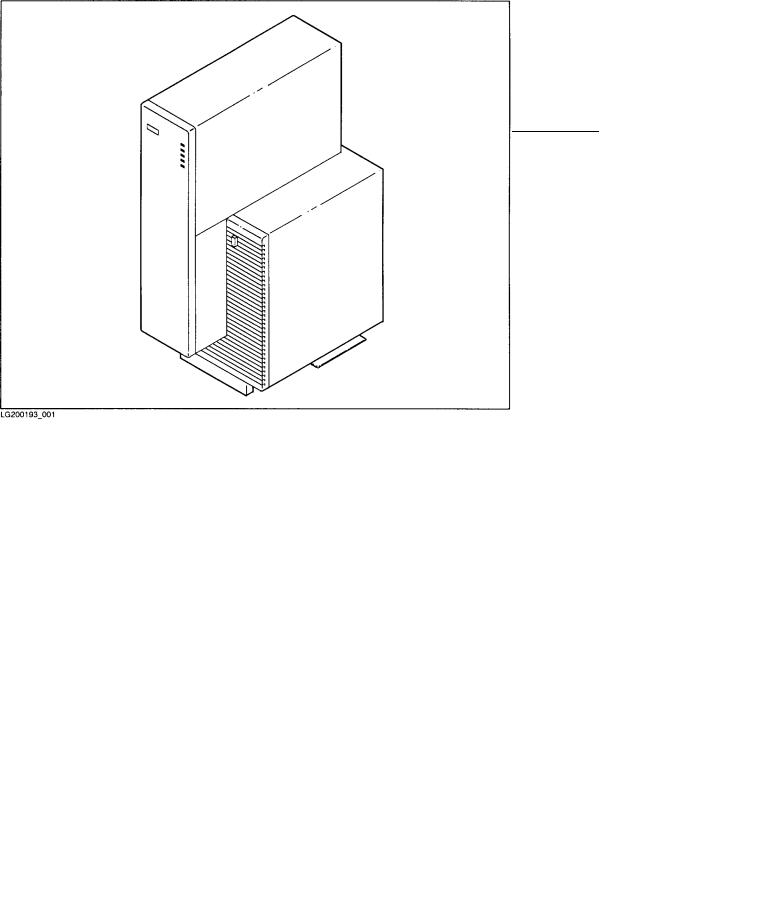
The System Unit
The system unit is contains the computer system itself. The front of the central section contains the disk drive bays. The rear of the central section holds the system card and graphic device cards. The \shoulder" section to the right of the central section contains the EISA (Extended Industry Standard Architecture) card bay and the cooling fans. At the bottom of the entire unit is the power supply.
The system unit is intended for deskside placement.
Figure 1-1. The System Unit
1-2 Your HP Apollo 9000 Model 750 Computer
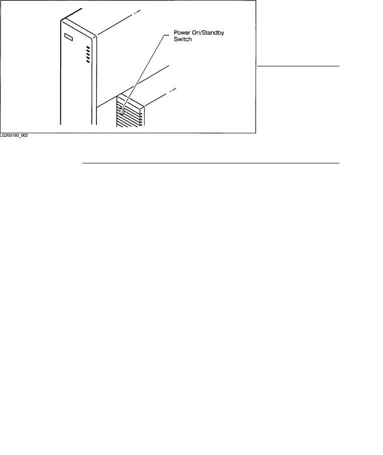
The Power On/Standby Switch
The switch that you use to turn on your HP Apollo 9000 Model 750 is located on the in the front of the system unit's right \shoulder." (See Figure 1-2.) This switch is actually a power on/standby switch. It is not the same as a power switch.
When you attach the power cable to the connector on the power supply and plug that cable into a power source, electric power is available from the power supply. When you turn on the power on/standby switch, that electrical power is distributed to the rest of the system unit.
Warning |
Do not assume that all power to the computer is off just |
|
because the power on/standby switch has been turned off. |
|
To completely remove power from you computer, unplug the |
|
power cable from the power outlet and disconnect that cable |
|
from the power supply. |
|
|
Figure 1-2. Location of the P ower On/Standby Switch
Your HP Apollo 9000 Model 750 Computer 1-3

Understanding the LEDs
In the front of the system unit's center section is a hinged cover. When the cover is closed, ve LEDs can be viewed through small \windo ws". Beside each window is a symbol indicating the meaning associated with the activity of each LED. Table 1-1 describes the activit y of the lights when the HP-UX operating system is running on your computer.
Table 1-1. LED Symbols and Their Meanings
Symbol |
LED Activity |
Meaning |
|
|
|
|
On/O |
Power on/standby |
|
|
|
|
Flashing |
Transmitting to LAN |
|
|
|
|
Flashing |
Receiving from LAN |
|
|
|
|
Flashing |
Disk activit y |
|
|
|
|
|
Slow ash |
System \heartbeat" |
|
|
|
|
|
|
|
|
|
|
|
Note |
If you have been working on your system successfully , and the |
|
\heartbeat" LED remains o or on for a long period of time, |
|
it may mean that your system is \h ung" (incapable of further |
|
processing). See Chapter 6 for suggestions on ho w to deal with |
|
this condition. |
|
|
1-4 Your HP Apollo 9000 Model 750 Computer
|
Figure 1-3. LED Windows |
|
|
Note |
It takes a substantial amount of time (2|5 minutes) for your |
|
computer to start the HP-UX operating system. During this |
|
time, the behavior of these LED indicators (and the others |
|
hidden behind the cover) is not controlled by HP-UX. Do not |
|
interpret the behavior of the LEDS as illustrated by Table 1-1 |
|
until after HP-UX has nished booting. |
|
|
Your HP Apollo 9000 Model 750 Computer 1-5
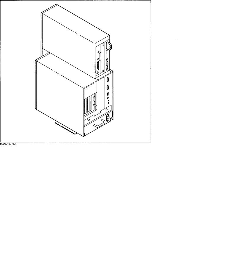
The Back of the System Unit
In back of the system unit are connectors you can use to attach peripherals to your computer. The connectors are mounted on bulkheads: metal panels that cover portions of the rear of the computer. You can get access to most of the internal parts of your computer by removing some of these bulkheads. You willnd descriptions of these internal parts in Chapter 5.
Figure 1-4. The Back of the System Unit
1-6 Your HP Apollo 9000 Model 750 Computer

The System Bulkhead
The system bulkhead is the rightmost and tallest of the bulkheads in the back of the system. (See Figure 1-4.) The I/O connectors and switches on this bulkhead are listed in Table 1-2 and illustrated in Figure 1-5.
|
Table 1-2. |
|
|
I/O Connector |
Use |
or Switch |
|
|
|
SCSI |
Used to attach external devices to the builtin SCSI (Small |
|
Computer Systems Interface) controller. |
|
|
HP-HIL |
Used to connect HP-HIL (Human Interface Link) devices to the |
|
system. The keyboard is an HP-HIL device. |
|
|
Parallel |
Used to connect external devices to the builtin parallel interface. |
|
Many printers are have parallel interfaces which may be used with |
|
this connector. |
|
|
Thin LAN |
Used to attach the system to an Ethernet LAN (Local Area |
|
Network) that uses a BNC-type connector. Either this connector or |
|
the AUI connector may be used. |
|
|
AUI |
Used to attach the system to an Ethernet LAN (Local Area |
|
Network) that requires an external MAU (Medium Access Unit). |
|
Either this connector or the Thin LAN connector may be used. |
|
|
RS-232 |
Each of these connectors may be used to connect external devices to |
|
the builtin serial interfaces. Most printers and modems can use |
|
these connectors. |
|
|
Audio |
Used to drive an external speaker or other audio device. |
|
|
Reset switch |
Restarts the computer by resetting the operating system. |
|
|
Service/Normal |
Used only during man ufacturing. You will not need to use this |
switch |
switch. |
|
|
Your HP Apollo 9000 Model 750 Computer 1-7

Figure 1-5. Connectors Mounted on the System Bulkhead
1-8 Your HP Apollo 9000 Model 750 Computer

The Power Supply Bulkhead
This covers the power supply. It has a plug connector for the power cord. The power supply bulkhead is below the other bulkheads at the bottom of the system unit as you view it from the rear. See Figure 1-6.
Figure 1-6. The Power Supply Bulkhead
Your HP Apollo 9000 Model 750 Computer 1-9

Graphic Device Bulkheads
If your computer system includes a bitmapped display, you will nd the bulkhead for a graphic device to the left of the system bulkhead in the upper portion of the system unit. Your system may be equipped with two graphic display devices; if so, there may be two graphic device bulkheads.
If your system is a server, it will probably not have any graphic devices at this location.
You can have any of three types of graphic device in your computer:
Color graphic |
This type of device has three BNC connectors (one for each for |
card |
red, blue, and green). (See Figure 1-7). These are connected |
|
by a cable to three similar connectors on a color display |
|
monitor. |
Grayscale |
This type of device has one BNC connector. (See Figure 1-8). |
graphic card |
This is connected by a cable to a similar connector on a |
|
grayscale display monitor. |
Graphic |
This type of device has a special connector. (See Figure 1-9.) |
interface card |
It is connected to an external graphic processor, which in turn |
|
is connected to a video display monitor. |
1-10 Your HP Apollo 9000 Model 750 Computer

Figure 1-7. Color Graphic Card Bulkhead
Your HP Apollo 9000 Model 750 Computer 1-11
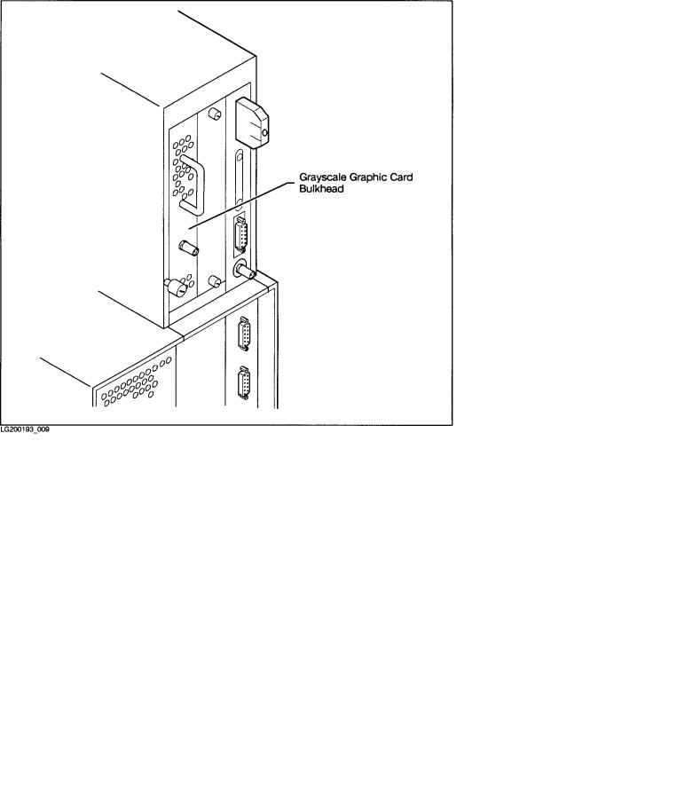
Figure 1-8. Grayscale Graphic Card Bulkhead
1-12 Your HP Apollo 9000 Model 750 Computer

Figure 1-9. Graphic Interface Card Bulkhead
Your HP Apollo 9000 Model 750 Computer 1-13
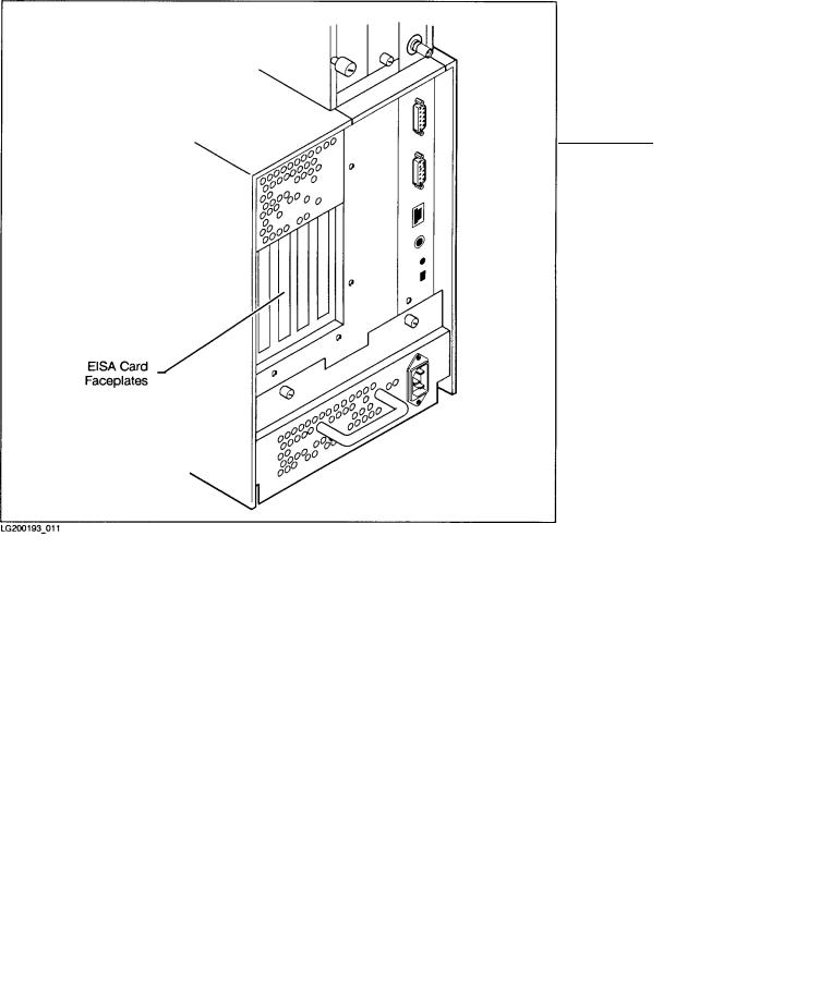
Access to the EISA Card Faceplates
Your HP Apollo 9000 Model 750 includes four slots for EISA (Extended Industry Standard Architecture) circuit cards. These slots are in the EISA card bay above the power supply on the left side of the system unit (as viewed from the back). See Figure 1-10.
An EISA card has a faceplate upon which one or more connectors may be mounted. There are four vertical openings in the rear panel of the EISA card bay. These openings allow access to the faceplates of the cards. If your system contains no EISA cards, the openings should be covered with blank faceplates.
1-14 Your HP Apollo 9000 Model 750 Computer
Figure 1-10. Openings for EISA Card F aceplates
 Loading...