


RTE A
System Generation and Installation Manual
Software Services and Technology Division
11000 Wolfe Road
Cupertino, CA 95014 9804
Manual Part No. 92077 90034 |
Printed in U.S.A. April 1995 |
E0495 |
Eighth Edition |

NOTICE
The information contained in this document is subject to change without notice.
HEWLETT PACKARD MAKES NO WARRANTY OF ANY KIND WITH REGARD TO THE MATERIAL, INCLUDING, BUT NOT LIMITED TO, THE IMPLIED WARRANTIES OF MERCHANTABILITY AND FITNESS FOR A PARTICULAR PURPOSE. Hewlett Packard shall not be liable for errors contained herein or for incidental or consequential damages in connection with the furnishing, performance, or use of this material.
Hewlett Packard assumes no responsibility for the use or reliability of its software on equipment that is not furnished by Hewlett Packard.
This document contains proprietary information which is protected by copyright. All rights are reserved. No part of this document may be photocopied, reproduced, or translated to another language without the prior written consent of Hewlett P ackard Company.
RESTRICTED RIGHTS LEGEND
Use, duplication, or disclosure by the Government is subject to restrictions as set forth in subparagraph (c) (1) (ii) of the Rights in Technical Data and Computer Software clause at
DFARs 252.227.7013.
Copyright E 1983 1987, 1989, 1990, 1992, 1993, 1995 by Hewlett Packard Company
2

Printing History
The Printing History below identifies the edition of this manual and any updates that are included. Periodi cally, update packages are distributed which contain replacement pages to be merged into the manual, including an updated copy of this printing history page. Also, the update may contain write in instructions.
Each reprinting of this manual will incorporate all past updates; however, no new information will be added. Thus, the reprinted copy will be identical in content to prior printings of the same edition with its user in serted update information. New editions of this manual will contain new information, as well as all updates.
To determine what manual edition and update is compatible with your current software revision code, refer to the Manual Numbering File. (The Manual Numbering File is included with your software. It consists of an •M" followed by a five digit product number.)
First Edition . . . . . . . . . . . . . . . . . . Jun 1983
Update 1 . . . . . . . . . . . . . . . . . . Aug 1983
Reprint . . . . . . . . . . . . . . . . . . . . . . Aug 1983
Update 2 . . . . . . . . . . . . . . . . . . Dec 1983
Reprint . . . . . . . . . . . . . . . . . . . . . . Dec 1983
Update 3 . . . . . . . . . . . . . . . . . . Jun 1984
Second Edition . . . . . . . . . . . . . . . Jan 1985
Third Edition . . . . . . . . . . . . . . . . . . Jan 1986
Update 1 . . . . . . . . . . . . . . . . . . Oct 1986
Fourth Edition . . . . . . . . . . . . . . . . Aug 1987
Update 1 . . . . . . . . . . . . . . . . . . Jan 1989
Fifth Edition . . . . . . . . . . . . . . . . . . Jul 1990
Sixth Edition . . . . . . . . . . . . . . . . . Dec 1992
Seventh Edition . . . . . . . . . . . . . . Nov 1993
Eighth Edition . . . . . . . . . . . . . . . . Apr 1995
. . . . . . . . . . . . . . . . . . . . . . . . . . . . . . . . . . . . . .
. . . . . . . . . . . . . . . . . . . Replace Appendix G
. . . . . . . . . . . . . . . . . Update 1 incorporated
. . . . . . . . . . . . . . . . . . . . . . . . . . . . . . . . . . . . . .
. . . . . . . . . . . . . . . . . Update 2 incorporated
. . . . . . . Add 15 Mb disk, MAC disk, 9144, 7974, 2566
. . . . . . . . . . . . . . . . . . . . . . . . . . . . . . . . . . . . . .
. . . . . . . . . . . . . . . . . . . . . . . . . . . . . . . . . . . . . .
. . . . . . . . . . . . New drivers and peripherals
. . . . . . . . Rev. 5000 (Software Update 5.0)
. . . . . . . . Rev. 5010 (Software Update 5.1)
. . . . . . . . Rev. 5020 (Software Update 5.2)
. . . . . . . . Rev. 6000 (Software Update 6.0)
. . . . . . . . Rev. 6100 (Software Update 6.1)
. . . . . . . . Rev. 6200 (Software Update 6.2)
3/4


Preface
This manual provides information for generating and installing a new RTE A Operating System. The information consists of the following:
1.General descriptions of the complete process of creating a new RTE A Operating System, with an overview of each of the two major steps - system generation and installation.
2.How to run the system generator program RTAGN.
3.How to prepare the generator answer file required for RTE A generation.
4.Descriptions of generator command syntax and the effects of each of the commands.
5.How to install a new RTE A Operating System, replacing an existing RTE A Operating Sys tem.
6.How to prepare and install a memory based RTE A system.
The appendices provide examples of blank generation worksheets, generation and installation error messages, specific requirements for configuring various devices into the RTE A Operating System, requirements for generating and installing localizable systems, and other reference data.
Who should read this manual?
Anyone who needs to perform any of the following:
Prepare a system generation answer file.
Generate a new RTE A Operating System from an existing RTE A Operating System.
Install a new RTE A Operating System.
Boot up a new operating system.
Create a memory based RTE A system.
Refer to the RTE A System Design Manual, part number 92077 90013, for a conceptual discussion of the RTE A Operating System. Each subsystem also has its system generation and installation requirements. Refer to the associated subsystem manual for details.
5/6


Table of Contents
Chapter 1
General Information
Introduction . . . . . . . . . . . . . . . . . . . . . . . . . . . . . . . . . . . . . . . . . . . . . . . . . . . . . . . . . . . . . . . . |
1 1 |
System Generation . . . . . . . . . . . . . . . . . . . . . . . . . . . . . . . . . . . . . . . . . . . . . . . . . . . . . . . . . . . |
1 2 |
Running RTAGN . . . . . . . . . . . . . . . . . . . . . . . . . . . . . . . . . . . . . . . . . . . . . . . . . . . . . . . . |
1 4 |
Generation Answer File . . . . . . . . . . . . . . . . . . . . . . . . . . . . . . . . . . . . . . . . . . . . . . . . . . |
1 4 |
Commands . . . . . . . . . . . . . . . . . . . . . . . . . . . . . . . . . . . . . . . . . . . . . . . . . . . . . . . . . . . . . |
1 4 |
Comments . . . . . . . . . . . . . . . . . . . . . . . . . . . . . . . . . . . . . . . . . . . . . . . . . . . . . . . . . . . . . . |
1 4 |
Command String Syntax . . . . . . . . . . . . . . . . . . . . . . . . . . . . . . . . . . . . . . . . . . . . . . . . . . |
1 5 |
System Installation . . . . . . . . . . . . . . . . . . . . . . . . . . . . . . . . . . . . . . . . . . . . . . . . . . . . . . . . . . . |
1 5 |
Type 6 Program Files . . . . . . . . . . . . . . . . . . . . . . . . . . . . . . . . . . . . . . . . . . . . . . . . . . . . . |
1 6 |
The Boot Process . . . . . . . . . . . . . . . . . . . . . . . . . . . . . . . . . . . . . . . . . . . . . . . . . . . . . . . . |
1 6 |
Conventions Used in This Manual . . . . . . . . . . . . . . . . . . . . . . . . . . . . . . . . . . . . . . . . . . . . . . |
1 8 |
Chapter 2
Running the Generator
General Information . . . . . . . . . . . . . . . . . . . . . . . . . . . . . . . . . . . . . . . . . . . . . . . . . . . . . . . . . |
2 1 |
The RTAGN Runstring . . . . . . . . . . . . . . . . . . . . . . . . . . . . . . . . . . . . . . . . . . . . . . . . . . . . . . . |
2 1 |
Command File . . . . . . . . . . . . . . . . . . . . . . . . . . . . . . . . . . . . . . . . . . . . . . . . . . . . . . . . . . . . . . |
2 2 |
List File . . . . . . . . . . . . . . . . . . . . . . . . . . . . . . . . . . . . . . . . . . . . . . . . . . . . . . . . . . . . . . . . . . . . |
2 2 |
System File . . . . . . . . . . . . . . . . . . . . . . . . . . . . . . . . . . . . . . . . . . . . . . . . . . . . . . . . . . . . . . . . . |
2 3 |
Snapshot File . . . . . . . . . . . . . . . . . . . . . . . . . . . . . . . . . . . . . . . . . . . . . . . . . . . . . . . . . . . . . . . |
2 3 |
Overlaying Files . . . . . . . . . . . . . . . . . . . . . . . . . . . . . . . . . . . . . . . . . . . . . . . . . . . . . . . . . . . . . |
2 4 |
Chapter 3
Initialization Phase
Conserving Space . . . . . . . . . . . . . . . . . . . . . . . . . . . . . . . . . . . . . . . . . . . . . . . . . . . . . . . . . . . . |
3 1 |
Links . . . . . . . . . . . . . . . . . . . . . . . . . . . . . . . . . . . . . . . . . . . . . . . . . . . . . . . . . . . . . . . . . . . . . . |
3 2 |
Chapter 4
System Relocation Phase
Relocating Modules . . . . . . . . . . . . . . . . . . . . . . . . . . . . . . . . . . . . . . . . . . . . . . . . . . . . . . . . . . |
4 1 |
System Modules . . . . . . . . . . . . . . . . . . . . . . . . . . . . . . . . . . . . . . . . . . . . . . . . . . . . . . . . . |
4 1 |
Driver Modules . . . . . . . . . . . . . . . . . . . . . . . . . . . . . . . . . . . . . . . . . . . . . . . . . . . . . . . . . |
4 1 |
Libraries . . . . . . . . . . . . . . . . . . . . . . . . . . . . . . . . . . . . . . . . . . . . . . . . . . . . . . . . . . . . . . . . . . . |
4 2 |
System Relocation Phase Commands . . . . . . . . . . . . . . . . . . . . . . . . . . . . . . . . . . . . . . . . . . . |
4 2 |
RELOCATE Command . . . . . . . . . . . . . . . . . . . . . . . . . . . . . . . . . . . . . . . . . . . . . . . . . . |
4 3 |
SEARCH Command . . . . . . . . . . . . . . . . . . . . . . . . . . . . . . . . . . . . . . . . . . . . . . . . . . . . . |
4 3 |
MSEARCH Command . . . . . . . . . . . . . . . . . . . . . . . . . . . . . . . . . . . . . . . . . . . . . . . . . . . |
4 3 |
LOCC Command . . . . . . . . . . . . . . . . . . . . . . . . . . . . . . . . . . . . . . . . . . . . . . . . . . . . . . . . |
4 4 |
BLOCC Command . . . . . . . . . . . . . . . . . . . . . . . . . . . . . . . . . . . . . . . . . . . . . . . . . . . . . . |
4 5 |
DISPLAY Command . . . . . . . . . . . . . . . . . . . . . . . . . . . . . . . . . . . . . . . . . . . . . . . . . . . . . |
4 5 |
LENTRIES Command . . . . . . . . . . . . . . . . . . . . . . . . . . . . . . . . . . . . . . . . . . . . . . . . . . . |
4 5 |
7

ALIGN Command . . . . . . . . . . . . . . . . . . . . . . . . . . . . . . . . . . . . . . . . . . . . . . . . . . . . . . . |
4 5 |
END Command . . . . . . . . . . . . . . . . . . . . . . . . . . . . . . . . . . . . . . . . . . . . . . . . . . . . . . . . . |
4 5 |
System Partitioning Concerns . . . . . . . . . . . . . . . . . . . . . . . . . . . . . . . . . . . . . . . . . . . . . . . . . . |
4 6 |
TG Command . . . . . . . . . . . . . . . . . . . . . . . . . . . . . . . . . . . . . . . . . . . . . . . . . . . . . . . . . . . |
4 6 |
PARTITION (PA) Command . . . . . . . . . . . . . . . . . . . . . . . . . . . . . . . . . . . . . . . . . . . . . . |
4 8 |
Chapter 5
OS Module/Driver Partition Phase
General Description . . . . . . . . . . . . . . . . . . . . . . . . . . . . . . . . . . . . . . . . . . . . . . . . . . . . . . . . . |
5 1 |
ALIGN Command . . . . . . . . . . . . . . . . . . . . . . . . . . . . . . . . . . . . . . . . . . . . . . . . . . . . . . . . . . . |
5 6 |
Partition Configurations . . . . . . . . . . . . . . . . . . . . . . . . . . . . . . . . . . . . . . . . . . . . . . . . . . . . . . |
5 7 |
Chapter 6
Table Generation Phase
General Description . . . . . . . . . . . . . . . . . . . . . . . . . . . . . . . . . . . . . . . . . . . . . . . . . . . . . . . . . |
6 1 |
Interface and Device Tables . . . . . . . . . . . . . . . . . . . . . . . . . . . . . . . . . . . . . . . . . . . . . . . |
6 1 |
Node Lists . . . . . . . . . . . . . . . . . . . . . . . . . . . . . . . . . . . . . . . . . . . . . . . . . . . . . . . . . . . . . . |
6 2 |
Interrupt Table . . . . . . . . . . . . . . . . . . . . . . . . . . . . . . . . . . . . . . . . . . . . . . . . . . . . . . . . . . |
6 3 |
The System I/O Configuration Worksheet . . . . . . . . . . . . . . . . . . . . . . . . . . . . . . . . . . . . . . . |
6 3 |
The IFT/DVT Worksheet . . . . . . . . . . . . . . . . . . . . . . . . . . . . . . . . . . . . . . . . . . . . . . . . . . . . . |
6 5 |
Example IFT/DVT Worksheet for an HP IB Card . . . . . . . . . . . . . . . . . . . . . . . . . . . . |
6 6 |
Example IFT/DVT Worksheet for a SCSI Card . . . . . . . . . . . . . . . . . . . . . . . . . . . . . . . |
6 7 |
Making Use of Defaults . . . . . . . . . . . . . . . . . . . . . . . . . . . . . . . . . . . . . . . . . . . . . . . . . . . . . . |
6 8 |
IFT and DVT Parameter Defaults . . . . . . . . . . . . . . . . . . . . . . . . . . . . . . . . . . . . . . . . . . . . . . |
6 8 |
Building the Answer File . . . . . . . . . . . . . . . . . . . . . . . . . . . . . . . . . . . . . . . . . . . . . . . . . . . . . . |
6 9 |
Table Generation Phase Commands . . . . . . . . . . . . . . . . . . . . . . . . . . . . . . . . . . . . . . . . . . . . |
6 10 |
IFT Command . . . . . . . . . . . . . . . . . . . . . . . . . . . . . . . . . . . . . . . . . . . . . . . . . . . . . . . . . . |
6 10 |
IFT Example . . . . . . . . . . . . . . . . . . . . . . . . . . . . . . . . . . . . . . . . . . . . . . . . . . . . . . . . |
6 12 |
DVT Command . . . . . . . . . . . . . . . . . . . . . . . . . . . . . . . . . . . . . . . . . . . . . . . . . . . . . . . . . |
6 13 |
END Command . . . . . . . . . . . . . . . . . . . . . . . . . . . . . . . . . . . . . . . . . . . . . . . . . . . . . . . . . |
6 18 |
NODE Command . . . . . . . . . . . . . . . . . . . . . . . . . . . . . . . . . . . . . . . . . . . . . . . . . . . . . . . |
6 18 |
END Command . . . . . . . . . . . . . . . . . . . . . . . . . . . . . . . . . . . . . . . . . . . . . . . . . . . . . . . . . |
6 19 |
INT Command . . . . . . . . . . . . . . . . . . . . . . . . . . . . . . . . . . . . . . . . . . . . . . . . . . . . . . . . . . |
6 19 |
Chapter 7
Memory Allocation Phase
Allocating Class Numbers . . . . . . . . . . . . . . . . . . . . . . . . . . . . . . . . . . . . . . . . . . . . . . . . . . . . . |
7 1 |
Allocating Resource Numbers . . . . . . . . . . . . . . . . . . . . . . . . . . . . . . . . . . . . . . . . . . . . . . . . . |
7 1 |
Allocating Debug Table Entries . . . . . . . . . . . . . . . . . . . . . . . . . . . . . . . . . . . . . . . . . . . . . . . . |
7 2 |
Allocating ID Segments . . . . . . . . . . . . . . . . . . . . . . . . . . . . . . . . . . . . . . . . . . . . . . . . . . . . . . |
7 2 |
Allocating Memory Descriptors . . . . . . . . . . . . . . . . . . . . . . . . . . . . . . . . . . . . . . . . . . . . . . . . |
7 3 |
Allocating System Available Memory (SAM) . . . . . . . . . . . . . . . . . . . . . . . . . . . . . . . . . . . . |
7 3 |
Allocating Extended System Available Memory (XSAM) . . . . . . . . . . . . . . . . . . . . . . . . . . |
7 3 |
Specifying Class Buffer Limits . . . . . . . . . . . . . . . . . . . . . . . . . . . . . . . . . . . . . . . . . . . . . . . . . |
7 4 |
Specifying Background Priority and Timeslice Quantum . . . . . . . . . . . . . . . . . . . . . . . . . . . |
7 4 |
Specifying Shared Programs . . . . . . . . . . . . . . . . . . . . . . . . . . . . . . . . . . . . . . . . . . . . . . . . . . . |
7 4 |
Allocating an Extended Schedule Table . . . . . . . . . . . . . . . . . . . . . . . . . . . . . . . . . . . . . . . . . |
7 5 |
Specifying System Memory Block . . . . . . . . . . . . . . . . . . . . . . . . . . . . . . . . . . . . . . . . . . . . . . |
7 5 |
Specifying Concurrent Users . . . . . . . . . . . . . . . . . . . . . . . . . . . . . . . . . . . . . . . . . . . . . . . . . . |
7 5 |
Specifying LOGOF Buffer Limits . . . . . . . . . . . . . . . . . . . . . . . . . . . . . . . . . . . . . . . . . . . . . . |
7 5 |
8

Setting Up System Common . . . . . . . . . . . . . . . . . . . . . . . . . . . . . . . . . . . . . . . . . . . . . . . . . . . |
7 6 |
Allocating System Message Block . . . . . . . . . . . . . . . . . . . . . . . . . . . . . . . . . . . . . . . . . . . . . . |
7 6 |
Specifying Security Tables . . . . . . . . . . . . . . . . . . . . . . . . . . . . . . . . . . . . . . . . . . . . . . . . . . . . . |
7 7 |
Specifying System Default Libraries . . . . . . . . . . . . . . . . . . . . . . . . . . . . . . . . . . . . . . . . . . . . |
7 7 |
Memory Allocation Phase Commands . . . . . . . . . . . . . . . . . . . . . . . . . . . . . . . . . . . . . . . . . . |
7 8 |
Class Number Command CLAS . . . . . . . . . . . . . . . . . . . . . . . . . . . . . . . . . . . . . . . . . . . . |
7 8 |
Resource Number Command RESN . . . . . . . . . . . . . . . . . . . . . . . . . . . . . . . . . . . . . . . . |
7 9 |
ID Segment Command ID . . . . . . . . . . . . . . . . . . . . . . . . . . . . . . . . . . . . . . . . . . . . . . . . |
7 9 |
Memory Descriptor Command RS . . . . . . . . . . . . . . . . . . . . . . . . . . . . . . . . . . . . . . . . . |
7 10 |
System Available Memory Command SAM . . . . . . . . . . . . . . . . . . . . . . . . . . . . . . . . . . |
7 10 |
Class Limits Command CL . . . . . . . . . . . . . . . . . . . . . . . . . . . . . . . . . . . . . . . . . . . . . . . . |
7 11 |
Background Priority Command BG . . . . . . . . . . . . . . . . . . . . . . . . . . . . . . . . . . . . . . . . . |
7 11 |
Quantum Timeslice Command QU . . . . . . . . . . . . . . . . . . . . . . . . . . . . . . . . . . . . . . . . . |
7 11 |
Shared Program Command SP . . . . . . . . . . . . . . . . . . . . . . . . . . . . . . . . . . . . . . . . . . . . . |
7 12 |
System Memory Block Command MB . . . . . . . . . . . . . . . . . . . . . . . . . . . . . . . . . . . . . . |
7 12 |
Concurrent User Command US . . . . . . . . . . . . . . . . . . . . . . . . . . . . . . . . . . . . . . . . . . . . |
7 12 |
LOGOF Buffer Limit Command LB . . . . . . . . . . . . . . . . . . . . . . . . . . . . . . . . . . . . . . . . |
7 12 |
Labeled Common Commands . . . . . . . . . . . . . . . . . . . . . . . . . . . . . . . . . . . . . . . . . . . . . |
7 13 |
Unlabeled (Blank) Common Command COM . . . . . . . . . . . . . . . . . . . . . . . . . . . . . . . |
7 13 |
System Message Catalog Relocation . . . . . . . . . . . . . . . . . . . . . . . . . . . . . . . . . . . . . . . . |
7 13 |
Library Command LIB . . . . . . . . . . . . . . . . . . . . . . . . . . . . . . . . . . . . . . . . . . . . . . . . . . . |
7 14 |
Chapter 8
System Installation Concepts and Considerations
Types of Systems . . . . . . . . . . . . . . . . . . . . . . . . . . . . . . . . . . . . . . . . . . . . . . . . . . . . . . . . . . . . . |
8 1 |
Host and Target Systems . . . . . . . . . . . . . . . . . . . . . . . . . . . . . . . . . . . . . . . . . . . . . . . . . . . . . . |
8 1 |
Type 6 Program Files . . . . . . . . . . . . . . . . . . . . . . . . . . . . . . . . . . . . . . . . . . . . . . . . . . . . . . . . . |
8 2 |
Loading RTE A Programs and Subsystems . . . . . . . . . . . . . . . . . . . . . . . . . . . . . . . . . . . . . . |
8 2 |
Using RTE_INSTALL.CMD . . . . . . . . . . . . . . . . . . . . . . . . . . . . . . . . . . . . . . . . . . . . . . |
8 4 |
Product Installation Defaults . . . . . . . . . . . . . . . . . . . . . . . . . . . . . . . . . . . . . . . . . . |
8 5 |
Target Directory Defaults . . . . . . . . . . . . . . . . . . . . . . . . . . . . . . . . . . . . . . . . . . . . . |
8 5 |
RTE Variable Defaults . . . . . . . . . . . . . . . . . . . . . . . . . . . . . . . . . . . . . . . . . . . . . . . . |
8 6 |
NS ARPA/1000 Variable Defaults . . . . . . . . . . . . . . . . . . . . . . . . . . . . . . . . . . . . . . |
8 7 |
LP Spooler Variable Defaults . . . . . . . . . . . . . . . . . . . . . . . . . . . . . . . . . . . . . . . . . . |
8 7 |
Mail/1000 Variable Defaults . . . . . . . . . . . . . . . . . . . . . . . . . . . . . . . . . . . . . . . . . . . |
8 7 |
Pascal/1000 Variable Defaults . . . . . . . . . . . . . . . . . . . . . . . . . . . . . . . . . . . . . . . . . . |
8 7 |
Image/1000 II Variable Defaults . . . . . . . . . . . . . . . . . . . . . . . . . . . . . . . . . . . . . . . |
8 8 |
The Boot Process . . . . . . . . . . . . . . . . . . . . . . . . . . . . . . . . . . . . . . . . . . . . . . . . . . . . . . . . . . . . |
8 9 |
Boot From Disk . . . . . . . . . . . . . . . . . . . . . . . . . . . . . . . . . . . . . . . . . . . . . . . . . . . . . . . . . |
8 10 |
Boot From Cartridge, Magnetic, or DAT Tape Drive . . . . . . . . . . . . . . . . . . . . . . . . . . |
8 10 |
Boot From PROM . . . . . . . . . . . . . . . . . . . . . . . . . . . . . . . . . . . . . . . . . . . . . . . . . . . . . . . |
8 10 |
Boot From a DS Link . . . . . . . . . . . . . . . . . . . . . . . . . . . . . . . . . . . . . . . . . . . . . . . . . . . . |
8 10 |
Boot From a LAN Link . . . . . . . . . . . . . . . . . . . . . . . . . . . . . . . . . . . . . . . . . . . . . . . . . . . |
8 11 |
Target System Installation . . . . . . . . . . . . . . . . . . . . . . . . . . . . . . . . . . . . . . . . . . . . . . . . . . . . . |
8 11 |
Chapter 9
Disk Based System Installation Procedure
Prepare the Boot Command File . . . . . . . . . . . . . . . . . . . . . . . . . . . . . . . . . . . . . . . . . . . . . . . |
9 2 |
Echoing Commands . . . . . . . . . . . . . . . . . . . . . . . . . . . . . . . . . . . . . . . . . . . . . . . . . . . . . . |
9 2 |
Mirrored Disk Configuration . . . . . . . . . . . . . . . . . . . . . . . . . . . . . . . . . . . . . . . . . . . . . . |
9 2 |
Specifying the System . . . . . . . . . . . . . . . . . . . . . . . . . . . . . . . . . . . . . . . . . . . . . . . . . . . . |
9 2 |
9

Specifying Memory Size . . . . . . . . . . . . . . . . . . . . . . . . . . . . . . . . . . . . . . . . . . . . . . . . . . |
9 3 |
Specifying Bad Pages . . . . . . . . . . . . . . . . . . . . . . . . . . . . . . . . . . . . . . . . . . . . . . . . . . . . . |
9 3 |
Mounting Disk Volumes . . . . . . . . . . . . . . . . . . . . . . . . . . . . . . . . . . . . . . . . . . . . . . . . . . |
9 3 |
Setting Up the Swap File . . . . . . . . . . . . . . . . . . . . . . . . . . . . . . . . . . . . . . . . . . . . . . . . . . |
9 4 |
Specifying the Scratch LU . . . . . . . . . . . . . . . . . . . . . . . . . . . . . . . . . . . . . . . . . . . . . . . . . |
9 4 |
Turning Session Accounting On/Off . . . . . . . . . . . . . . . . . . . . . . . . . . . . . . . . . . . . . . . . . |
9 5 |
Setting System Parameters . . . . . . . . . . . . . . . . . . . . . . . . . . . . . . . . . . . . . . . . . . . . . . . . |
9 5 |
Setting Master Security Code . . . . . . . . . . . . . . . . . . . . . . . . . . . . . . . . . . . . . . . . . . . . . . |
9 5 |
Restoring Programs . . . . . . . . . . . . . . . . . . . . . . . . . . . . . . . . . . . . . . . . . . . . . . . . . . . . . . |
9 6 |
Reserved Partition Definition . . . . . . . . . . . . . . . . . . . . . . . . . . . . . . . . . . . . . . . . . . . . . . |
9 6 |
Terminating Input . . . . . . . . . . . . . . . . . . . . . . . . . . . . . . . . . . . . . . . . . . . . . . . . . . . . . . . . |
9 7 |
Example Boot Command File . . . . . . . . . . . . . . . . . . . . . . . . . . . . . . . . . . . . . . . . . . . . . |
9 7 |
Installing System, Snapshot, and Command Files . . . . . . . . . . . . . . . . . . . . . . . . . . . . . . . . . |
9 8 |
Installation Considerations . . . . . . . . . . . . . . . . . . . . . . . . . . . . . . . . . . . . . . . . . . . . . . . . |
9 8 |
FPUT and BOOTEX for New Disk Configurations . . . . . . . . . . . . . . . . . . . . . . . . . . . |
9 9 |
Preparation for Boot . . . . . . . . . . . . . . . . . . . . . . . . . . . . . . . . . . . . . . . . . . . . . . . . . . . . . |
9 11 |
Establishing New CI Directories and Programs . . . . . . . . . . . . . . . . . . . . . . . . . . . . . . . . . . . |
9 13 |
SYSTEM Directory . . . . . . . . . . . . . . . . . . . . . . . . . . . . . . . . . . . . . . . . . . . . . . . . . . . . . . |
9 14 |
HELP Directory . . . . . . . . . . . . . . . . . . . . . . . . . . . . . . . . . . . . . . . . . . . . . . . . . . . . . . . . . |
9 14 |
CATALOGS Directory . . . . . . . . . . . . . . . . . . . . . . . . . . . . . . . . . . . . . . . . . . . . . . . . . . . |
9 14 |
LIBRARIES Directory . . . . . . . . . . . . . . . . . . . . . . . . . . . . . . . . . . . . . . . . . . . . . . . . . . . |
9 14 |
PROGRAMS Directory . . . . . . . . . . . . . . . . . . . . . . . . . . . . . . . . . . . . . . . . . . . . . . . . . . |
9 14 |
SCRATCH Directory . . . . . . . . . . . . . . . . . . . . . . . . . . . . . . . . . . . . . . . . . . . . . . . . . . . . . |
9 14 |
CMDFILES Directory . . . . . . . . . . . . . . . . . . . . . . . . . . . . . . . . . . . . . . . . . . . . . . . . . . . . |
9 14 |
CI Commands Implemented in Separate Programs . . . . . . . . . . . . . . . . . . . . . . . . . . . |
9 15 |
Format System . . . . . . . . . . . . . . . . . . . . . . . . . . . . . . . . . . . . . . . . . . . . . . . . . . . . . . . . . . . . . . |
9 15 |
Booting the Target System . . . . . . . . . . . . . . . . . . . . . . . . . . . . . . . . . . . . . . . . . . . . . . . . . . . . |
9 16 |
Checking the Target System for Proper Operation . . . . . . . . . . . . . . . . . . . . . . . . . . . . . . . . |
9 18 |
Setting Up the Startup Program and Welcome File . . . . . . . . . . . . . . . . . . . . . . . . . . . . . . . . |
9 18 |
CM as a Secondary Program . . . . . . . . . . . . . . . . . . . . . . . . . . . . . . . . . . . . . . . . . . . . . . . . . . |
9 19 |
Backing Up the Target System . . . . . . . . . . . . . . . . . . . . . . . . . . . . . . . . . . . . . . . . . . . . . . . . . |
9 19 |
Upgrading A990 Firmware . . . . . . . . . . . . . . . . . . . . . . . . . . . . . . . . . . . . . . . . . . . . . . . . . . . . |
9 20 |
Troubleshooting the Download Process . . . . . . . . . . . . . . . . . . . . . . . . . . . . . . . . . . . . . . |
9 22 |
Setting Switches for Autoboot . . . . . . . . . . . . . . . . . . . . . . . . . . . . . . . . . . . . . . . . . . . . . . . . . |
9 23 |
Installing Optional Subsystems . . . . . . . . . . . . . . . . . . . . . . . . . . . . . . . . . . . . . . . . . . . . . . . . |
9 23 |
Installing DS Transparency Software . . . . . . . . . . . . . . . . . . . . . . . . . . . . . . . . . . . . . . . . . . . . |
9 25 |
Chapter 10
Installing a Memory Based System
Assembling the Required Files . . . . . . . . . . . . . . . . . . . . . . . . . . . . . . . . . . . . . . . . . . . . . . . . . 10 1 Run BUILD to Create the Merged System File . . . . . . . . . . . . . . . . . . . . . . . . . . . . . . . . . . 10 2 Operational Phases . . . . . . . . . . . . . . . . . . . . . . . . . . . . . . . . . . . . . . . . . . . . . . . . . . . . . . 10 3 BUILD Completion Codes . . . . . . . . . . . . . . . . . . . . . . . . . . . . . . . . . . . . . . . . . . . . . . . . 10 5 Example Command File . . . . . . . . . . . . . . . . . . . . . . . . . . . . . . . . . . . . . . . . . . . . . . . . . . 10 6 Installing Merged System File on a Bootable Medium . . . . . . . . . . . . . . . . . . . . . . . . . . . . . 10 7 PROM . . . . . . . . . . . . . . . . . . . . . . . . . . . . . . . . . . . . . . . . . . . . . . . . . . . . . . . . . . . . . . . . . 10 7 CTD Tape . . . . . . . . . . . . . . . . . . . . . . . . . . . . . . . . . . . . . . . . . . . . . . . . . . . . . . . . . . . . . . 10 8 Magnetic or DAT Tape . . . . . . . . . . . . . . . . . . . . . . . . . . . . . . . . . . . . . . . . . . . . . . . . . . . 10 8 Disk Volume . . . . . . . . . . . . . . . . . . . . . . . . . . . . . . . . . . . . . . . . . . . . . . . . . . . . . . . . . . . . 10 8 FMGR Cartridge . . . . . . . . . . . . . . . . . . . . . . . . . . . . . . . . . . . . . . . . . . . . . . . . . . . . . . . . 10 9 From Disk, Using BOOTEX . . . . . . . . . . . . . . . . . . . . . . . . . . . . . . . . . . . . . . . . . . . . . . 10 9 Booting the Target System . . . . . . . . . . . . . . . . . . . . . . . . . . . . . . . . . . . . . . . . . . . . . . . . . . . . 10 9 Special Considerations . . . . . . . . . . . . . . . . . . . . . . . . . . . . . . . . . . . . . . . . . . . . . . . . . . . 10 11
10
Testing the Target System . . . . . . . . . . . . . . . . . . . . . . . . . . . . . . . . . . . . . . . . . . . . . . . . . . . . . |
10 12 |
Backing Up the Target System . . . . . . . . . . . . . . . . . . . . . . . . . . . . . . . . . . . . . . . . . . . . . . . . . |
10 13 |
Setting Switches for Automatic Boot . . . . . . . . . . . . . . . . . . . . . . . . . . . . . . . . . . . . . . . . . . . . |
10 13 |
Chapter 11
Multiuser and Spooling Setup
Group and User Management Program (GRUMP) . . . . . . . . . . . . . . . . . . . . . . . . . . . . . . . |
11 1 |
Establishing Multiuser Accounts . . . . . . . . . . . . . . . . . . . . . . . . . . . . . . . . . . . . . . . . . . . . . . . |
11 5 |
PROMT Program . . . . . . . . . . . . . . . . . . . . . . . . . . . . . . . . . . . . . . . . . . . . . . . . . . . . . . . . |
11 5 |
RESTR Program . . . . . . . . . . . . . . . . . . . . . . . . . . . . . . . . . . . . . . . . . . . . . . . . . . . . . . . . |
11 6 |
LOGON Program . . . . . . . . . . . . . . . . . . . . . . . . . . . . . . . . . . . . . . . . . . . . . . . . . . . . . . . |
11 7 |
Shared CI . . . . . . . . . . . . . . . . . . . . . . . . . . . . . . . . . . . . . . . . . . . . . . . . . . . . . . . . . . . . . . . . . . |
11 7 |
CDS Library . . . . . . . . . . . . . . . . . . . . . . . . . . . . . . . . . . . . . . . . . . . . . . . . . . . . . . . . . . . . . . . . |
11 7 |
Appendix A
Error Messages
RTAGN Errors . . . . . . . . . . . . . . . . . . . . . . . . . . . . . . . . . . . . . . . . . . . . . . . . . . . . . . . . . . . . . . |
A 1 |
BUILD Program Error Messages . . . . . . . . . . . . . . . . . . . . . . . . . . . . . . . . . . . . . . . . . . . . . . |
A 8 |
VCP Loader Errors . . . . . . . . . . . . . . . . . . . . . . . . . . . . . . . . . . . . . . . . . . . . . . . . . . . . . . . . . . |
A 11 |
Appendix B
Worksheets
Initialization and System Relocation Worksheet . . . . . . . . . . . . . . . . . . . . . . . . . . . . . . . . . . |
B 2 |
System I/O Configuration Worksheet . . . . . . . . . . . . . . . . . . . . . . . . . . . . . . . . . . . . . . . . . . . |
B 6 |
IFT/DVT Worksheet . . . . . . . . . . . . . . . . . . . . . . . . . . . . . . . . . . . . . . . . . . . . . . . . . . . . . . . . . |
B 7 |
Table Generation Worksheet . . . . . . . . . . . . . . . . . . . . . . . . . . . . . . . . . . . . . . . . . . . . . . . . . . |
B 8 |
Memory Allocation Worksheet . . . . . . . . . . . . . . . . . . . . . . . . . . . . . . . . . . . . . . . . . . . . . . . . |
B 9 |
Appendix C
Configuring a Disk Subsystem
Disk Subsystem Categories . . . . . . . . . . . . . . . . . . . . . . . . . . . . . . . . . . . . . . . . . . . . . . . . . . . . |
C 2 |
Disk Configuration Steps . . . . . . . . . . . . . . . . . . . . . . . . . . . . . . . . . . . . . . . . . . . . . . . . . . . . . |
C 3 |
File System Considerations . . . . . . . . . . . . . . . . . . . . . . . . . . . . . . . . . . . . . . . . . . . . . . . . . . . |
C 4 |
Configuring SCSI Disks . . . . . . . . . . . . . . . . . . . . . . . . . . . . . . . . . . . . . . . . . . . . . . . . . . . . . . . |
C 4 |
SCSI Disk Driver Parameters . . . . . . . . . . . . . . . . . . . . . . . . . . . . . . . . . . . . . . . . . . . . . . |
C 5 |
SCSI Address (DP1) . . . . . . . . . . . . . . . . . . . . . . . . . . . . . . . . . . . . . . . . . . . . . . . . . |
C 5 |
Disk Drive Unit Number (DP2) . . . . . . . . . . . . . . . . . . . . . . . . . . . . . . . . . . . . . . . . |
C 5 |
Pass Through Fence (DP3) . . . . . . . . . . . . . . . . . . . . . . . . . . . . . . . . . . . . . . . . . . . . |
C 5 |
Starting Block Number (DP4 and DP5) . . . . . . . . . . . . . . . . . . . . . . . . . . . . . . . . . |
C 5 |
Number of Tracks (DP6) . . . . . . . . . . . . . . . . . . . . . . . . . . . . . . . . . . . . . . . . . . . . . . |
C 5 |
Number of Blocks per Track (DP7) . . . . . . . . . . . . . . . . . . . . . . . . . . . . . . . . . . . . . |
C 5 |
Driver Parameter 8 (DP8) . . . . . . . . . . . . . . . . . . . . . . . . . . . . . . . . . . . . . . . . . . . . . |
C 6 |
Configuring Non CS/80 HP IB Disks . . . . . . . . . . . . . . . . . . . . . . . . . . . . . . . . . . . . . . . . . . . |
C 7 |
Physical Disk Structure . . . . . . . . . . . . . . . . . . . . . . . . . . . . . . . . . . . . . . . . . . . . . . . . . . . |
C 7 |
Logical Disk Structure . . . . . . . . . . . . . . . . . . . . . . . . . . . . . . . . . . . . . . . . . . . . . . . . . . . . |
C 7 |
Surface Mode . . . . . . . . . . . . . . . . . . . . . . . . . . . . . . . . . . . . . . . . . . . . . . . . . . . . . . . |
C 7 |
Cylinder Mode . . . . . . . . . . . . . . . . . . . . . . . . . . . . . . . . . . . . . . . . . . . . . . . . . . . . . . |
C 7 |
Non CS/80 HP IB Disk Driver DD*30 Parameters . . . . . . . . . . . . . . . . . . . . . . . . . . . . |
C 9 |
HP IB Address (DP1) . . . . . . . . . . . . . . . . . . . . . . . . . . . . . . . . . . . . . . . . . . . . . . . . |
C 9 |
11

Disk Drive Unit Number (DP2) . . . . . . . . . . . . . . . . . . . . . . . . . . . . . . . . . . . . . . . . |
C 9 |
Starting Head for LU (DP3) . . . . . . . . . . . . . . . . . . . . . . . . . . . . . . . . . . . . . . . . . . . |
C 10 |
Starting Cylinder for LU (DP4) . . . . . . . . . . . . . . . . . . . . . . . . . . . . . . . . . . . . . . . . |
C 10 |
Number of Spares for LU (DP5) . . . . . . . . . . . . . . . . . . . . . . . . . . . . . . . . . . . . . . . |
C 10 |
Number of Tracks for LU (DP6) . . . . . . . . . . . . . . . . . . . . . . . . . . . . . . . . . . . . . . . |
C 10 |
Number of Blocks per Track for Disk (DP7) . . . . . . . . . . . . . . . . . . . . . . . . . . . . . |
C 10 |
Number of Surfaces for LU (DP8) . . . . . . . . . . . . . . . . . . . . . . . . . . . . . . . . . . . . . . |
C 10 |
Configuring a RAM Disk . . . . . . . . . . . . . . . . . . . . . . . . . . . . . . . . . . . . . . . . . . . . . . . . . |
C 11 |
Configuring CS/80 Disks . . . . . . . . . . . . . . . . . . . . . . . . . . . . . . . . . . . . . . . . . . . . . . . . . . . . . . |
C 12 |
CS/80 Driver Parameters . . . . . . . . . . . . . . . . . . . . . . . . . . . . . . . . . . . . . . . . . . . . . . . . . . |
C 12 |
HP IB Address (DP1) . . . . . . . . . . . . . . . . . . . . . . . . . . . . . . . . . . . . . . . . . . . . . . . . |
C 13 |
Disk Drive Unit Number (DP2) . . . . . . . . . . . . . . . . . . . . . . . . . . . . . . . . . . . . . . . . |
C 14 |
Starting Block of Disk (DP3,DP4,DP5) . . . . . . . . . . . . . . . . . . . . . . . . . . . . . . . . . . |
C 14 |
Number of Tracks for LU (DP6) . . . . . . . . . . . . . . . . . . . . . . . . . . . . . . . . . . . . . . . |
C 14 |
Number of Blocks per Track for Disk (DP7) . . . . . . . . . . . . . . . . . . . . . . . . . . . . . |
C 15 |
Reserved Parameter (DP8) . . . . . . . . . . . . . . . . . . . . . . . . . . . . . . . . . . . . . . . . . . . . |
C 15 |
Starting Block Address of Disk Cache . . . . . . . . . . . . . . . . . . . . . . . . . . . . . . . . . . . |
C 15 |
Address of First Cache Block . . . . . . . . . . . . . . . . . . . . . . . . . . . . . . . . . . . . . . . . . . |
C 15 |
Sample CS/80 Worksheets . . . . . . . . . . . . . . . . . . . . . . . . . . . . . . . . . . . . . . . . . . . . . . . . . |
C 16 |
Sample 7907 Worksheet, Fixed Disk (Unit 0) . . . . . . . . . . . . . . . . . . . . . . . . . . . . . |
C 16 |
Sample 7907 Worksheet, Removable Disk (Unit 1) . . . . . . . . . . . . . . . . . . . . . . . . |
C 16 |
Sample 7908 Worksheet . . . . . . . . . . . . . . . . . . . . . . . . . . . . . . . . . . . . . . . . . . . . . . |
C 16 |
Sample CTD Worksheet . . . . . . . . . . . . . . . . . . . . . . . . . . . . . . . . . . . . . . . . . . . . . . |
C 17 |
Sample 7911 Worksheet . . . . . . . . . . . . . . . . . . . . . . . . . . . . . . . . . . . . . . . . . . . . . . |
C 17 |
Sample 7912 Worksheet . . . . . . . . . . . . . . . . . . . . . . . . . . . . . . . . . . . . . . . . . . . . . . |
C 17 |
Sample 7914 Worksheet . . . . . . . . . . . . . . . . . . . . . . . . . . . . . . . . . . . . . . . . . . . . . . |
C 18 |
Sample 7933/35 Worksheet . . . . . . . . . . . . . . . . . . . . . . . . . . . . . . . . . . . . . . . . . . . . |
C 18 |
Sample 7941/7942 Worksheet . . . . . . . . . . . . . . . . . . . . . . . . . . . . . . . . . . . . . . . . . . |
C 19 |
Sample 7945/7946 Worksheet . . . . . . . . . . . . . . . . . . . . . . . . . . . . . . . . . . . . . . . . . . |
C 19 |
Sample 9122C/D Worksheet . . . . . . . . . . . . . . . . . . . . . . . . . . . . . . . . . . . . . . . . . . . |
C 19 |
Sample 9133H Floppy Worksheet . . . . . . . . . . . . . . . . . . . . . . . . . . . . . . . . . . . . . . |
C 20 |
Special Considerations for the 7902 Disk Drive . . . . . . . . . . . . . . . . . . . . . . . . . . . . . . . . . . . |
C 20 |
Sample 7902 Disk Worksheet . . . . . . . . . . . . . . . . . . . . . . . . . . . . . . . . . . . . . . . . . . |
C 21 |
7902 Disk Worksheet Sample . . . . . . . . . . . . . . . . . . . . . . . . . . . . . . . . . . . . . . . . . . |
C 22 |
Special Considerations for Model 6 Integrated Disk Drives . . . . . . . . . . . . . . . . . . . . . . . . |
C 22 |
Sample Model 6 Integrated Disk Worksheet . . . . . . . . . . . . . . . . . . . . . . . . . . . . . |
C 23 |
Sample 9133/9134/9121 Disk Worksheet . . . . . . . . . . . . . . . . . . . . . . . . . . . . . . . . . |
C 24 |
Microsystems With Integrated Peripherals (243x/8x) . . . . . . . . . . . . . . . . . . . . . . . . . . . . . . |
C 25 |
Address and Unit Specification on Microsystems . . . . . . . . . . . . . . . . . . . . . . . . . |
C 26 |
Special Considerations for the 7906M Disk Drive . . . . . . . . . . . . . . . . . . . . . . . . . . . . . . . . . |
C 26 |
Using the Worksheet . . . . . . . . . . . . . . . . . . . . . . . . . . . . . . . . . . . . . . . . . . . . . . . . . . . . . |
C 27 |
7906M Disk Configuration Worksheet Cylinders: . . . . . . . . . . . . . . . . . . . . . . . . . |
C 28 |
7906 Disk Configuration Worksheet . . . . . . . . . . . . . . . . . . . . . . . . . . . . . . . . . . . . |
C 29 |
Special Considerations for MAC Drives . . . . . . . . . . . . . . . . . . . . . . . . . . . . . . . . . . . . . . . . . |
C 30 |
Appendix D
GEN Records
Parameter Default Records . . . . . . . . . . . . . . . . . . . . . . . . . . . . . . . . . . . . . . . . . . . . . . . . . . . |
D 1 |
Processing . . . . . . . . . . . . . . . . . . . . . . . . . . . . . . . . . . . . . . . . . . . . . . . . . . . . . . . . . . . . . . |
D 2 |
Example Default File . . . . . . . . . . . . . . . . . . . . . . . . . . . . . . . . . . . . . . . . . . . . . . . . . . . . . |
D 2 |
Format of the Default GEN Record . . . . . . . . . . . . . . . . . . . . . . . . . . . . . . . . . . . . . . . . |
D 3 |
System Partitioning Records . . . . . . . . . . . . . . . . . . . . . . . . . . . . . . . . . . . . . . . . . . . . . . . . . . . |
D 4 |
Processing . . . . . . . . . . . . . . . . . . . . . . . . . . . . . . . . . . . . . . . . . . . . . . . . . . . . . . . . . . . . . . |
D 4 |
12

Entry Records . . . . . . . . . . . . . . . . . . . . . . . . . . . . . . . . . . . . . . . . . . . . . . . . . . . . . . . |
D 4 |
Module Flag Records . . . . . . . . . . . . . . . . . . . . . . . . . . . . . . . . . . . . . . . . . . . . . . . . . |
D 4 |
Format of System Partitioning GEN Records . . . . . . . . . . . . . . . . . . . . . . . . . . . . . . . . . |
D 5 |
Entry Records . . . . . . . . . . . . . . . . . . . . . . . . . . . . . . . . . . . . . . . . . . . . . . . . . . . . . . . |
D 5 |
Module Flag Records . . . . . . . . . . . . . . . . . . . . . . . . . . . . . . . . . . . . . . . . . . . . . . . . . |
D 5 |
Appendix E
Device and Interface Driver Tables
Appendix F
Default DVT Entries By Driver Name
DD*00 . . . . . . . . . . . . . . . . . . . . . . . . . . . . . . . . . . . . . . . . . . . . . . . . . . . . . . . . . . . . . . . . . . . . . |
F 1 |
DD*12 . . . . . . . . . . . . . . . . . . . . . . . . . . . . . . . . . . . . . . . . . . . . . . . . . . . . . . . . . . . . . . . . . . . . . |
F 1 |
DD*20 . . . . . . . . . . . . . . . . . . . . . . . . . . . . . . . . . . . . . . . . . . . . . . . . . . . . . . . . . . . . . . . . . . . . . |
F 2 |
DD*23 . . . . . . . . . . . . . . . . . . . . . . . . . . . . . . . . . . . . . . . . . . . . . . . . . . . . . . . . . . . . . . . . . . . . . |
F 2 |
DD*24 . . . . . . . . . . . . . . . . . . . . . . . . . . . . . . . . . . . . . . . . . . . . . . . . . . . . . . . . . . . . . . . . . . . . . |
F 2 |
DD*30 . . . . . . . . . . . . . . . . . . . . . . . . . . . . . . . . . . . . . . . . . . . . . . . . . . . . . . . . . . . . . . . . . . . . . |
F 3 |
DD*33 . . . . . . . . . . . . . . . . . . . . . . . . . . . . . . . . . . . . . . . . . . . . . . . . . . . . . . . . . . . . . . . . . . . . . |
F 4 |
DD*36 . . . . . . . . . . . . . . . . . . . . . . . . . . . . . . . . . . . . . . . . . . . . . . . . . . . . . . . . . . . . . . . . . . . . . |
F 10 |
DDC00 . . . . . . . . . . . . . . . . . . . . . . . . . . . . . . . . . . . . . . . . . . . . . . . . . . . . . . . . . . . . . . . . . . . . |
F 10 |
DDC12 . . . . . . . . . . . . . . . . . . . . . . . . . . . . . . . . . . . . . . . . . . . . . . . . . . . . . . . . . . . . . . . . . . . . |
F 12 |
DDQ30 . . . . . . . . . . . . . . . . . . . . . . . . . . . . . . . . . . . . . . . . . . . . . . . . . . . . . . . . . . . . . . . . . . . . |
F 13 |
DDM30 . . . . . . . . . . . . . . . . . . . . . . . . . . . . . . . . . . . . . . . . . . . . . . . . . . . . . . . . . . . . . . . . . . . . |
F 13 |
GEN27 . . . . . . . . . . . . . . . . . . . . . . . . . . . . . . . . . . . . . . . . . . . . . . . . . . . . . . . . . . . . . . . . . . . . |
F 14 |
Appendix G
Example System Generation Answer File
Appendix H
VCP Boot Information
VCP Errors . . . . . . . . . . . . . . . . . . . . . . . . . . . . . . . . . . . . . . . . . . . . . . . . . . . . . . . . . . . . . . . . . |
H 1 |
General Boot Procedure . . . . . . . . . . . . . . . . . . . . . . . . . . . . . . . . . . . . . . . . . . . . . . . . . . . . . . |
H 1 |
Parity Errors . . . . . . . . . . . . . . . . . . . . . . . . . . . . . . . . . . . . . . . . . . . . . . . . . . . . . . . . . . . . |
H 3 |
Loading Your System from Disk . . . . . . . . . . . . . . . . . . . . . . . . . . . . . . . . . . . . . . . . . . . . . . . |
H 3 |
Examples . . . . . . . . . . . . . . . . . . . . . . . . . . . . . . . . . . . . . . . . . . . . . . . . . . . . . . . . . . . . . . . |
H 5 |
Loading Your System from CTD . . . . . . . . . . . . . . . . . . . . . . . . . . . . . . . . . . . . . . . . . . . . . . . |
H 9 |
Examples . . . . . . . . . . . . . . . . . . . . . . . . . . . . . . . . . . . . . . . . . . . . . . . . . . . . . . . . . . . . . . . |
H 9 |
Loading Your System from PROM . . . . . . . . . . . . . . . . . . . . . . . . . . . . . . . . . . . . . . . . . . . . . |
H 10 |
Loading Your System over a DS Link . . . . . . . . . . . . . . . . . . . . . . . . . . . . . . . . . . . . . . . . . . . |
H 11 |
Loading Your System over a LAN Link . . . . . . . . . . . . . . . . . . . . . . . . . . . . . . . . . . . . . . . . . |
H 12 |
Loading Your System from Magnetic or DAT Tape . . . . . . . . . . . . . . . . . . . . . . . . . . . . . . . . |
H 13 |
Examples . . . . . . . . . . . . . . . . . . . . . . . . . . . . . . . . . . . . . . . . . . . . . . . . . . . . . . . . . . . . . . . |
H 13 |
Loading Your System from 243x/8x Integrated Disks . . . . . . . . . . . . . . . . . . . . . . . . . . . . . . |
H 14 |
Examples . . . . . . . . . . . . . . . . . . . . . . . . . . . . . . . . . . . . . . . . . . . . . . . . . . . . . . . . . . . . . . . |
H 15 |
13

Appendix I
BUILD Program
Introduction . . . . . . . . . . . . . . . . . . . . . . . . . . . . . . . . . . . . . . . . . . . . . . . . . . . . . . . . . . . . . . . . |
I 1 |
BUILD Program Operation . . . . . . . . . . . . . . . . . . . . . . . . . . . . . . . . . . . . . . . . . . . . . . . . . . . |
I 2 |
The BUILD Runstring . . . . . . . . . . . . . . . . . . . . . . . . . . . . . . . . . . . . . . . . . . . . . . . . . . . . |
I 2 |
BUILD Commands . . . . . . . . . . . . . . . . . . . . . . . . . . . . . . . . . . . . . . . . . . . . . . . . . . . . . . |
I 3 |
BUILD Phase One . . . . . . . . . . . . . . . . . . . . . . . . . . . . . . . . . . . . . . . . . . . . . . . . . . . |
I 3 |
BUILD Phase Two . . . . . . . . . . . . . . . . . . . . . . . . . . . . . . . . . . . . . . . . . . . . . . . . . . . |
I 3 |
BUILD Phase Three . . . . . . . . . . . . . . . . . . . . . . . . . . . . . . . . . . . . . . . . . . . . . . . . . |
I 3 |
Shareable EMA . . . . . . . . . . . . . . . . . . . . . . . . . . . . . . . . . . . . . . . . . . . . . . . . . . . . . . . . . |
I 5 |
BUILD Examples . . . . . . . . . . . . . . . . . . . . . . . . . . . . . . . . . . . . . . . . . . . . . . . . . . . . . . . . . . . |
I 5 |
BUILD Command Files . . . . . . . . . . . . . . . . . . . . . . . . . . . . . . . . . . . . . . . . . . . . . . . . . . . . . . |
I 9 |
Appendix J
Boot Extension BOOTEX
Boot Program Operation . . . . . . . . . . . . . . . . . . . . . . . . . . . . . . . . . . . . . . . . . . . . . . . . . . . . . |
J 1 |
ECHO Command . . . . . . . . . . . . . . . . . . . . . . . . . . . . . . . . . . . . . . . . . . . . . . . . . . . . . . . |
J 2 |
MI Command . . . . . . . . . . . . . . . . . . . . . . . . . . . . . . . . . . . . . . . . . . . . . . . . . . . . . . . . . . . |
J 2 |
SYSTEM/SNAP Commands . . . . . . . . . . . . . . . . . . . . . . . . . . . . . . . . . . . . . . . . . . . . . . . |
J 2 |
Memory Commands . . . . . . . . . . . . . . . . . . . . . . . . . . . . . . . . . . . . . . . . . . . . . . . . . . . . . |
J 3 |
Mounting Cartridges . . . . . . . . . . . . . . . . . . . . . . . . . . . . . . . . . . . . . . . . . . . . . . . . . . . . . |
J 3 |
Scratch LU . . . . . . . . . . . . . . . . . . . . . . . . . . . . . . . . . . . . . . . . . . . . . . . . . . . . . . . . . . . . . |
J 3 |
Bad Pages . . . . . . . . . . . . . . . . . . . . . . . . . . . . . . . . . . . . . . . . . . . . . . . . . . . . . . . . . . . . . . |
J 4 |
Restore Program Commands RP, ST, SZ, PR . . . . . . . . . . . . . . . . . . . . . . . . . . . . . . . . . |
J 5 |
Reserved Partition Assignment . . . . . . . . . . . . . . . . . . . . . . . . . . . . . . . . . . . . . . . . . . . . |
J 5 |
Reserved Partition Definition . . . . . . . . . . . . . . . . . . . . . . . . . . . . . . . . . . . . . . . . . . . . . . |
J 6 |
SWAP File Definition . . . . . . . . . . . . . . . . . . . . . . . . . . . . . . . . . . . . . . . . . . . . . . . . . . . . |
J 6 |
Timeslicing, Swapping, Security Code, Session Accounting . . . . . . . . . . . . . . . . . . . . . |
J 7 |
EN (End) Command . . . . . . . . . . . . . . . . . . . . . . . . . . . . . . . . . . . . . . . . . . . . . . . . . . . . . |
J 7 |
Example of a Boot Command File . . . . . . . . . . . . . . . . . . . . . . . . . . . . . . . . . . . . . . . . . . |
J 8 |
Skipping the Boot Program . . . . . . . . . . . . . . . . . . . . . . . . . . . . . . . . . . . . . . . . . . . . . . . . . . . . |
J 8 |
Appendix K
Installing Localizable Programs
Localized Programs . . . . . . . . . . . . . . . . . . . . . . . . . . . . . . . . . . . . . . . . . . . . . . . . . . . . . . . . . . |
K 1 |
File Naming Conventions . . . . . . . . . . . . . . . . . . . . . . . . . . . . . . . . . . . . . . . . . . . . . . . . . |
K 2 |
Language ID Numbers . . . . . . . . . . . . . . . . . . . . . . . . . . . . . . . . . . . . . . . . . . . . . . . |
K 2 |
Hierarchical File System (CI) File Names . . . . . . . . . . . . . . . . . . . . . . . . . . . . . . . |
K 2 |
FMGR File Names . . . . . . . . . . . . . . . . . . . . . . . . . . . . . . . . . . . . . . . . . . . . . . . . . . |
K 2 |
System Generation and Installation . . . . . . . . . . . . . . . . . . . . . . . . . . . . . . . . . . . . . . . . . . . . |
K 3 |
System Design Considerations . . . . . . . . . . . . . . . . . . . . . . . . . . . . . . . . . . . . . . . . . . . . . |
K 3 |
Terminals . . . . . . . . . . . . . . . . . . . . . . . . . . . . . . . . . . . . . . . . . . . . . . . . . . . . . . . . . . . |
K 3 |
Memory Requirements . . . . . . . . . . . . . . . . . . . . . . . . . . . . . . . . . . . . . . . . . . . . . . . |
K 3 |
System Generation . . . . . . . . . . . . . . . . . . . . . . . . . . . . . . . . . . . . . . . . . . . . . . . . . . . . . . . |
K 3 |
Relocating the Appropriate Driver . . . . . . . . . . . . . . . . . . . . . . . . . . . . . . . . . . . . . |
K 4 |
Configuring Terminals for 8 Data Bit Support . . . . . . . . . . . . . . . . . . . . . . . . . . . . |
K 4 |
Relocating the System Message Relocatables . . . . . . . . . . . . . . . . . . . . . . . . . . . . . |
K 4 |
System Installation . . . . . . . . . . . . . . . . . . . . . . . . . . . . . . . . . . . . . . . . . . . . . . . . . . . . . . . |
K 5 |
Placing Binary Message Catalogs into /CATALOGS . . . . . . . . . . . . . . . . . . . . . . . |
K 5 |
Installing the Message Monitor (If Required) . . . . . . . . . . . . . . . . . . . . . . . . . . . . |
K 6 |
14

Placing Help Files xxxxx.Hnnn in the /SYSTEM Directory . . . . . . . . . . . . . . . . . |
K 6 |
Creating Directory /HELPxxx for Localized Help Files . . . . . . . . . . . . . . . . . . . . |
K 6 |
Placing Localized Programs into /PROGRAMSxxx . . . . . . . . . . . . . . . . . . . . . . . . |
K 6 |
Placing Unlocalized Programs in Directory /PROGRAMS . . . . . . . . . . . . . . . . . |
K 6 |
Setting Up NLTERMCAP.TXT . . . . . . . . . . . . . . . . . . . . . . . . . . . . . . . . . . . . . . . . |
K 6 |
Using NLSID to Set Terminal Language ID . . . . . . . . . . . . . . . . . . . . . . . . . . . . . . |
K 7 |
Preparing the Welcome File . . . . . . . . . . . . . . . . . . . . . . . . . . . . . . . . . . . . . . . . . . . |
K 8 |
Booting Up the New System . . . . . . . . . . . . . . . . . . . . . . . . . . . . . . . . . . . . . . . . . . . |
K 8 |
Localizable System and Subsystem Files . . . . . . . . . . . . . . . . . . . . . . . . . . . . . . . . . . . . . |
K 8 |
Error Messages . . . . . . . . . . . . . . . . . . . . . . . . . . . . . . . . . . . . . . . . . . . . . . . . . . . . . . . . . . |
K 11 |
15

List of Illustrations
Figure 1 1 |
RTE A System Generation Process . . . . . . . . . . . . . . . . . . . . . . . . . . . . . . . . |
1 3 |
Figure 1 2 |
RTE A System Installation Process . . . . . . . . . . . . . . . . . . . . . . . . . . . . . . . . |
1 7 |
Figure 4 1 |
Results of Using the LOCC Command . . . . . . . . . . . . . . . . . . . . . . . . . . . . . |
4 4 |
Figure 5 1 |
Sample Memory Maps . . . . . . . . . . . . . . . . . . . . . . . . . . . . . . . . . . . . . . . . . . |
5 6 |
Figure 5 2 |
Sample Partitions . . . . . . . . . . . . . . . . . . . . . . . . . . . . . . . . . . . . . . . . . . . . . . . |
5 7 |
Figure 6 1 |
Example Node List Configuration . . . . . . . . . . . . . . . . . . . . . . . . . . . . . . . . . |
6 3 |
Figure 10 1 |
Memory Map of Example Memory Based System . . . . . . . . . . . . . . . . . . . |
10 7 |
Figure C 1 |
Arrangement of Disk Cylinders . . . . . . . . . . . . . . . . . . . . . . . . . . . . . . . . . . . |
C 8 |
Figure C 2 |
Track Access in Cylinder Mode . . . . . . . . . . . . . . . . . . . . . . . . . . . . . . . . . . . |
C 8 |
Figure C 3 |
7902 Dual Flexible Disk Drive . . . . . . . . . . . . . . . . . . . . . . . . . . . . . . . . . . . . |
C 20 |
Figure C 4 |
7906M Disk Drive . . . . . . . . . . . . . . . . . . . . . . . . . . . . . . . . . . . . . . . . . . . . . . |
C 26 |
Figure C 5 |
Example MAC Disk Generator Answer File Statements . . . . . . . . . . . . . . |
C 31 |
Tables
Table 5 1 |
Partitionable Driver List . . . . . . . . . . . . . . . . . . . . . . . . . . . . . . . . . . . . . . . . . |
5 2 |
Table 5 2 |
Partitionable System Module Sizes and Tag Area Requirements . . . . . . . |
5 4 |
Table 9 1 |
Processor Card Switch Settings . . . . . . . . . . . . . . . . . . . . . . . . . . . . . . . . . . . |
9 24 |
Table 10 1 |
Processor Card Switch Settings . . . . . . . . . . . . . . . . . . . . . . . . . . . . . . . . . . . |
10 14 |
Table E 1 |
Standard Generation File Entries . . . . . . . . . . . . . . . . . . . . . . . . . . . . . . . . . |
E 2 |
Table E 2 |
Terminal and Printer Default File Values . . . . . . . . . . . . . . . . . . . . . . . . . . . |
E 7 |
Table E 3 |
Flexible Disk Default File Values . . . . . . . . . . . . . . . . . . . . . . . . . . . . . . . . . |
E 8 |
Table E 4 |
9133A/9134A Disk (Four Volume Format) Default File Values . . . . . . . . |
E 9 |
Table E 5 |
9133B/9134B Disk (Single Volume Format) Default File Values . . . . . . . . |
E 10 |
Table E 6 |
9133D/H/L 9134D/H/L Default File Values . . . . . . . . . . . . . . . . . . . . . . . . . |
E 11 |
Table E 7 |
9133D/H/L Dual Sided Double Density Microfloppy Default File Values |
E 12 |
Table E 8 |
9122C/D Dual Sided Microfloppy Default File Values . . . . . . . . . . . . . . . . |
E 13 |
Table E 9 |
9121/9133A/B/XV Single Sided Microfloppy File Default Values . . . . . . . |
E 14 |
Table E 10 |
Magnetic and CS/80 Tape Default File Values . . . . . . . . . . . . . . . . . . . . . . . |
E 15 |
Table E 11 |
7906 Default File Values . . . . . . . . . . . . . . . . . . . . . . . . . . . . . . . . . . . . . . . . . |
E 16 |
Table E 12 |
7906M Default File Values . . . . . . . . . . . . . . . . . . . . . . . . . . . . . . . . . . . . . . . |
E 17 |
Table E 13 |
7920 Default File Values . . . . . . . . . . . . . . . . . . . . . . . . . . . . . . . . . . . . . . . . . |
E 18 |
Table E 14 |
7920M Default File Values . . . . . . . . . . . . . . . . . . . . . . . . . . . . . . . . . . . . . . . |
E 19 |
Table E 15 |
7925 Default File Values . . . . . . . . . . . . . . . . . . . . . . . . . . . . . . . . . . . . . . . . . |
E 20 |
Table E 16 |
7925M Default File Values . . . . . . . . . . . . . . . . . . . . . . . . . . . . . . . . . . . . . . . |
E 21 |
Table E 17 |
Cartridge Tape Drive File Default Values . . . . . . . . . . . . . . . . . . . . . . . . . . |
E 22 |
Table E 18 |
7907A Removable Disk Default File Values . . . . . . . . . . . . . . . . . . . . . . . . |
E 23 |
Table E 19 |
7907/08/11/12/14/33/41/42/45/46 Default File Values . . . . . . . . . . . . . . . . . . |
E 24 |
Table E 20 |
248x Default File Values . . . . . . . . . . . . . . . . . . . . . . . . . . . . . . . . . . . . . . . . . |
E 25 |
Table E 21 |
IFT Default File Values . . . . . . . . . . . . . . . . . . . . . . . . . . . . . . . . . . . . . . . . . |
E 26 |
Table E 22 |
7936 Default File Values . . . . . . . . . . . . . . . . . . . . . . . . . . . . . . . . . . . . . . . . . |
E 27 |
Table E 23 |
7937 Default File Values . . . . . . . . . . . . . . . . . . . . . . . . . . . . . . . . . . . . . . . . . |
E 28 |
Table E 24 |
7957 Default File Values . . . . . . . . . . . . . . . . . . . . . . . . . . . . . . . . . . . . . . . . . |
E 29 |
Table E 25 |
7958A/B Default File Values . . . . . . . . . . . . . . . . . . . . . . . . . . . . . . . . . . . . . |
E 30 |
Table E 26 |
7959/7963 Default File Values . . . . . . . . . . . . . . . . . . . . . . . . . . . . . . . . . . . . |
E 31 |
Table H 1 |
VCP Default Parameters for Boot . . . . . . . . . . . . . . . . . . . . . . . . . . . . . . . . . |
H 3 |
Table K 1 |
Localizable System and Subsystem Files . . . . . . . . . . . . . . . . . . . . . . . . . . . . |
K 9 |
16

General Information
Introduction
This manual provides the information required to generate and install a new RTE A Operating System. The generation process produces the system and snapshot files required to define the system to be installed. Generation does not affect the operation of the existing RTE A system. The system installation process makes the newly generated system operational.
The information is organized as follows:
Chapter 1 provides an overview of the RTE A system generation and system installation processes. It also describes the conventions used in this manual.
Chapter 2 describes how to run the RTE A generator program RTAGN and gives the RTAGN runstring syntax and describes the output files.
Chapters 3 describe the operation of the system generator program (RTAGN) and the through 7 generator commands. These chapters correspond to the various phases in the
generation process.
Chapter 8 contains general information on the system installation process.
Chapter 9 provides the installation procedure for a disk based RTE A system.
Chapter 10 provides the installation procedure for a memory based RTE A system.
Chapter 11 explains how to download a memory based system over a LAN and how to use the remote VCP.
Chapter 12 describes the multiuser and spooling features provided with the optional HP 92078A Virtual Code+ (VC+) Package.
Appendix A contains the generation and installation error messages.
Appendix B provides the generation worksheets used in preparing the generation answer file.
Appendix C provides procedures for configuring a disk subsystem.
Appendix D and Appendix E contain the generation requirements for drivers.
Appendix F lists default DVT entries by driver name.
General Information |
1 1 |

Appendix G contains a sample generation answer file.
Appendix H contains system boot information.
Appendix I describes the BUILD program used for creating a memory based system.
Appendix J describes the BOOTEX program.
Appendix K contains procedures for reconfiguring CS/80 disks.
Appendix L describes the requirements for generating and installing localizable systems.
System Generation
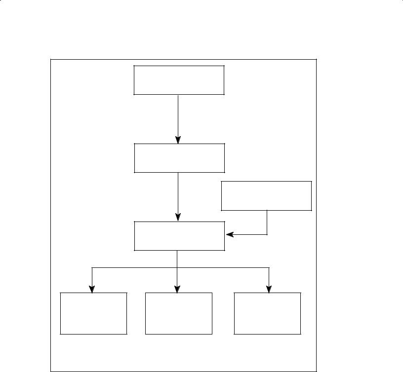
System generation consists of preparing a system generation answer file and running the system generator program RTAGN. The system generation process is shown in Figure 1 1. The system configuration planning portion includes following the instructions given in Chapters 3 through 7 of this manual with the aid of the worksheets and sample answer files provided. After the appropriate worksheets have been filled out, an existing answer file can be edited according to the worksheets to create a new system generation answer file. Then the system generator program RTAGN is run using the new answer file to create a system, a snapshot, and a list file. The system and snapshot files are used to install the new operating system.
Before system generation can be started, you must have the RTE A software available in the existing RTE operating system. If the RTE A software is furnished on DDS tape, CS/80 cartridge tape, or magnetic tape, you must restore the software onto the existing system. The media restoration procedures are given in the RTE A Primary System Software Installation Manual, part number 92077 90038, and the utilities used for the system generation are described in either the
RTE A User's Manual, part number 92077 90002, or the RTE A Backup and Disk Formatting Utilities Reference Manual, part number 92077 90004.
1 2 General Information
|
System Configuration |
|
|
Planning |
|
|
(Complete Worksheets) |
|
|
Edit Existing |
|
|
Answer File |
|
|
(New Answer File) |
|
|
|
RTE A Software |
|
|
Master |
|
|
Relocatables |
|
Run |
|
|
RTAGN |
|
Type 1 |
Type 3 |
Type 4 |
System |
Snapshot |
List |
File |
File |
File |
Figure 1 1. RTE A System Generation Process
General Information |
1 3 |

Running RTAGN
The system generator program RTAGN executes in five functional phases: initialization, system relocation, OS module/driver partition, table generation, and memory allocation. The generator accepts only those commands expected in each phase of execution.
1.Initialization Phase. In this phase, the generator initializes the tables, variables, and parameters used by the operating system.
2.System Relocation Phase. During this phase, the specified relocatable modules of the operating system are relocated.
3.OS Modules/Driver Partition Phase. In this phase, system modules and I/O drivers are relocated and grouped into physical partitions. Partitioning allows more system table space and the use of more system code, including large drivers.
4.Table Generation Phase. In this phase, space for various system tables is allocated and the system tables are configured.
5.Memory Allocation Phase. During this phase, space is allocated for ID segments, system available memory, system memory block, the maximum number of classes, resource numbers and memory descriptors, system common, and error message relocation. The number of shared programs, number of concurrent users, swapping limit, timeslice value, and default libraries to be searched are also defined.
Generation Answer File
A system generation answer file contains the commands needed to build an operating system using the system generator program RTAGN. Answer files are commonly constructed by editing an existing file, such as the primary system answer file listed in Appendix G of this manual. The primary system answer file is available on your primary system under the name PRIMARY.ANS.
The command entries in the answer file direct the generator operations. Comments also are included in the file to enable the reader to follow the generation process.
Commands
The generator requires commands in a specific order. In this manual, the commands are described in the order expected by the generator. If this order is not followed, the generator issues an error message.
In some cases, the generator accepts any one of a group of commands, as in the various relocation sections. These are terminated with the END command. An error message is issued if a command encountered by the generator is not one that is expected.
All generator commands can be entered with only two characters. The full command name may be used for clarity; for example, you may enter either LOCC or LO, BLOCC or BL.
Comments
Comments may be used anywhere in the answer file. These are particularly helpful when generating a new system because an existing answer file generally is edited to create the new answer file. A well commented answer file simplifies the editing process. An asterisk (*) in the first column of an entry indicates that the entire line is a comment line. This line will be written to the list file.
1 4 General Information
Comments may also appear at the end of some command lines. However, this form of commenting may be used only with commands in which the number of optional parameters is fixed, such as the RESN command or the ID command. Comments are not allowed on the same lines as commands such as the DVT command where the number of parameters may vary. To place comments at the end of a line, precede the comment with extra commas. Commas must be used as place holders for all parameters. If a command is expecting three parameters, then two commas will make the comment the third parameter. (The safest technique is to use five commas preceding a comment, because no commands have more than five parameters.)
Some sample comment formats are shown below:
*This is a comment line using an asterisk
*Two examples of using comments after a command:
REL,%PROGA::–23,, |
RELOCATION OF PROGA FROM LU 23 |
SEARCH,$SYSLB ,, |
SEARCH THE SYSTEM LIBRARY |
Command String Syntax
The commands used in the answer file are structured so that each command starts on a new line. A maximum of 80 characters can be entered in a command line. Each command may have several parameters, which must be separated by commas. The number of parameters may be fixed or variable, depending on the specific command.
Each parameter may also have subparameters, which must be separated by colons. The maximum number of subparameters allowed is six per parameter. Additional subparameters are ignored by the generator.
System Installation
System installation consists of generating a new system file, preparing the target system hardware and media for boot, booting the new system, setting up a primary program, establishing the account structure, spooling, and directories (if the optional HP 92078A Virtual Code+ Package is used), and backing up the new system. Figure 1 2 is a functional diagram of the system installation process.
The installation procedure differs for memory based and disk based systems. A memory based system in this case refers to a system in which program swapping or segmentation is not allowed. A special program named BUILD (described in Appendix I) is used to create a composite system file. The composite system file includes the system file produced in the system generation process and all type 6 program files required for the new operating system. This system can be run without a disk. A memory based system that is downloaded over a LAN is described in Chapter 11. A special case of a memory based system is the terminal less system that is built and then generated across the Distributed System Network. For details on generating a terminal less system across DS, refer to the DS/1000 IV Network Manager's Manual for RTE A and RTE 6/VM, part number 91750 90012.
A disk based system refers to one that boots from disk and one that allows program swapping and segmentation. All the files required for the new system must be installed on a medium bootable on the new system.
General Information |
1 5 |

The boot process brings the newly generated (target) system into operation. The new system can be generated from an existing (host) system which can be any RTE A or RTE 6/VM system.
The backup process is one means of preserving the new operating system in case of emergencies. It eliminates the need for regenerating the system in case the new system is destroyed.
Type 6 Program Files
Type 6 program files are produced by the program LINK. These files contain program code in memory image format, linked for a specific operating system. Such files are ready to be copied directly into a memory partition for execution.
The system file produced by the generator does not contain any programs because the generator does not relocate programs. It is necessary, however, that some programs be available to the system at boot time so that system operations can begin. These programs are described in Chapter 9.
The Boot Process
Booting is the process of loading an operating system into the computer and executing it. You can load a system from a disk, a cartridge tape drive (CTD), a magnetic tape, a DAT tape or a PROM module. You can also load a system from another computer over an HDLC link with DS or NS or in a local area network (LAN). The system can be booted manually by means of the virtual control panel (VCP) terminal, or automatically at power on by setting the switches on the processor card of the A Series computer.
The VCP terminal for a manual boot can be a local terminal or a remote terminal. The remote terminal is connected to the local system through a direct DS link or a LAN. A direct DS link is a distributed system connection with no intervening nodes (computers) on the DS network. Two computer systems so connected are called neighbors on the DS network. Booting over a LAN can be done from any computer system on the LAN; in other words, the system does not have to be a neighbor node.
Specific boot procedures are given in Chapters 9, 10, and 11. Appendix H contains detailed information on the boot parameters and several boot examples.
1 6 General Information

|
SNAPSHOT |
|
For disk based |
FILE |
For memory based |
|
||
system |
|
system |
|
SYSTEM |
|
|
FILE |
|
|
TYPE 6 |
RUN |
|
BUILD PROGRAM |
|
|
FILES |
|
|
(memory based system) |
|
|
|
|
|
|
COMPOSITE |
BOOTABLE |
|
SYSTEM |
MEDIUM |
|
FILE |
|
|
(memory based system) |
PREPARE |
BOOT THE SYSTEM |
|
TARGET DISK |
|
|
FOR BOOT |
|
|
|
NEW |
|
|
RTE A OPERATING |
BACKUP |
|
SYSTEM |
|
Figure 1 2. RTE A System Installation Process
General Information |
1 7 |

Conventions Used in This Manual
Optional parameters are placed in square brackets. For example, in the command
DVT,... [,TO:to] ..., etc.
the •TO:to" parameter is optional. In this case, the TO: portion of the parameter (TimeOut) is required when this option is specified.
Variables that you must supply are shown in lowercase italic letters. For example, the •to" parameter in the above command can be specified as:
DVT,... ,TO:3 ..., etc.
Commands or parameters that must be entered exactly as shown are in ALL CAPITAL LETTERS. For example, in the above example, the optional parameter must be specified as •TO:" followed by the variable •to".
The vertical bar (|) is used to indicate an OR condition. For example, the following entry
LE[,ON|OFF]
is the same as:
LE[,ON] or LE[,OFF]
The file names specified in the command parameters follow the file system naming conventions. A file can be specified by its name followed by the necessary subparameters. Throughout this manual, this is indicated in the command parameters as a file descriptor. A file can sometimes be specified as an I/O device. In this case, the parameter is indicated as a file. Refer to the RTE A User's Manual, part number 92077 90002, for details of the file descriptor.
The convention HP uses to refer to driver names has been changed from DD.nn to DD*nn. The HP driver relocatable file names of the form %DD.nn have also been changed from %DD.nn to %DD*nn. HP driver names in the NAM statement (DD.nn) and driver entry points (DD.nn) remain the same.
DD*nn Referenced driver name %DD*nn Driver relocatable file name DD.nn Driver name in NAM statement DD.nn Driver entry point
1 8 General Information
Running the Generator
General Information
The generator program RTAGN can run on either the RTE A or RTE 6/VM operating system. This is possible because the RTAGN input and output files are normal RTE files. All of these files can be specified in the runstring for RTAGN and all but the command file can be defaulted.
When the generator is run, it reads commands from the specified command file (typically the answer file) and begins constructing a system based on the commands. Information describing each phase of RTAGN and any file errors encountered are displayed at the terminal from which the generator was scheduled. When an error is found during the generation, the appropriate message is written to the list file, the offending command is skipped, and the generation continues. This allows the generation to proceed and scan for any further errors.
The output written to the list file can also be displayed at the terminal by using the RTAGN EC (echo) command. The ER (echo error) command also can be used to display only the error messages. Either command can be given at any time; the output is displayed from that point through completion of the generation process. At the end of the generation, RTAGN displays a message indicating the number of errors found and then terminates.
The RTAGN Runstring
RTAGN is scheduled for execution using the runstring:
CI> RTAGN command[,list[,system[,snap]]]
where: |
|
command |
is the parameter that specifies the name of the file that contains the generator |
|
entries and commands needed for system generation. |
list |
is an optional parameter that specifies the name of the list file to be produced |
|
by the generator. The default file name is SYLIST. |
system |
is an optional parameter that specifies the name of the system file to be |
|
produced by the generator. This file contains a memory image of the system. |
|
The default file name is SYSTEM. |
snap |
is an optional parameter that specifies the name of the snapshot file to be |
|
produced by the generator. The default file name is SNAP. |
Running the Generator |
2 1 |

The RTAGN runstring parameters must be entered in the order shown. If any default is used, the parameter position must be held with commas, as:
CI> RTAGN,CMDFIL,,,SNPS1
The above runstring specifies CMDFIL as the file from which generator commands are to be taken, defaults the list file to SYLIST and the system file to SYSTEM, and specifies SNPS1 as the snapshot file. If you omit all parameters, RTAGN will display the runstring syntax showing the parameters in the proper sequence.
If your answer file has a type extension of .ANS, any of the list, system, or snap file parameters can be specified as a dash (-). The - specifies that the name of the answer file is to be used with a type extension of .LST, .SYS, or .SNP for the list, system, or snap file, respectively. These files will overlay any existing files with the same name. For example:
CI> RU,RTAGN,SYSTEM1.ANS,–,–,–
will produce the files SYSTEM1.LST, SYSTEM1.SYS, and SYSTEM1.SNP.
Command File
A command file, also referred to as an answer file, is a source file constructed by the user that contains commands needed by the generator to generate the operating system. This file must be specified in the runstring. If a command file is not specified, the generator aborts after displaying the following message:
RU RTAGN COMMAND LIST SYSTEM SNAP
List File
The first line of the list file output by the generator contains the runstring used to schedule RTAGN. The next line contains the system time at the beginning of the generation. Following this header information, the file contains a listing of the input commands and comments, the program names, bounds, and entry points, as well as any errors encountered during the generation.
If the list file is not specified, the default file SYLIST will be created by RTAGN. If SYLIST already exists, the generator will not overlay it and will abort with the •File already exists" error message.
If the list file descriptor, as opposed to the file name, starts with an apostrophe (') or a caret (^) and if the specified file is in your current working directory or in a global directory, then the generator will overlay the file.
Any error messages output by RTAGN are written to the list file, followed with the line
** error **
In this way, error messages can be easily identified.
2 2 Running the Generator

System File
The system file is a type 1 file that contains the memory image of the operating system. This file is copied into memory and executed at system boot. If not specified, the default file SYSTEM will be created by RTAGN. If it already exists, it will not be overlaid. The generator will abort with the •File already exists" error message.
If the system file descriptor, as opposed to the file name, starts with an apostrophe (') or a caret
(^) and if the specified file is in your current working directory or in a global directory, then the generator will overlay the file. If, however, the existing file was specified with a security code, it will not be overlaid unless the new file name is specified with the same security code.
Snapshot File
The snapshot file is a type 3 file created by RTAGN to hold the generated system snapshot. It contains the values of system entry points, system library names, and other system information such as system checksums and system common checksum. If an entry point or module name is longer than sixteen characters, RTAGN ignores the additional characters when that entry point or module name is added to the snap file.
The snapshot file is required by LINK to load programs online. The snap file should be copied to /SYSTEM/SNAP.SNP because this is the default snap file name that LINK uses. Note that if an existing SNAP::0 file exists, it should be purged. Refer to the LINK SN command in the RTE A LINK User's Manual, part number 92077 90035, for details on the default snap file name that LINK uses. If the default snapshot file name is specified and this file already exists, it will not be overlaid. The generator will abort with the •File already exists" error message.
If the snap file descriptor, as opposed to the file name, starts with an apostrophe (') or a caret (^) and if the specified file is in your current working directory or in a global directory, then the generator will overlay the file. If, however, the existing file was specified with a security code, it will not be overlaid unless the new file name is specified with the same security code.
Running the Generator |
2 3 |

Overlaying Files
If the first character in a list, system, or snapshot file name specified in the generator runstring is an apostrophe ('), or if the file is defaulted with a dash (-), an existing file of the same name will be overlaid each time RTAGN is executed with that file specified. An existing snapshot file with the same name will also be overlaid if the first character is a caret (^). If, however, the file was originally specified with a security code, it will not be overlaid unless the new file specification includes the same security code.
If you specify a file name without the leading ' or ^ character, and the file already exists, it will not be overlaid by the generator. In this case, the generator will terminate immediately, displaying a duplicate file name error.
For example, if the generator runstring is:
CI> rtagn,comnd,=list,’outpt,snap
the file 'OUTPT will be created by the generator if it does not exist. If it does exist prior to running the generator, the old information will be overlaid by the new output from the generator. The file =LIST will be created if it does not exist; if a file by that name does exist, it will not be overlaid and the generator will abort with the message:
File already exists =LIST:::3:155
The file SNAP will also be created by the generator if it does not exist. If it does exist prior to running the generator, the generator will not overlay it and will abort with the file already exists message.
In the above example, the file 'OUTPT would not be overlaid, despite the leading ' character, if the original file was specified with a security code. For example:
|
New File |
Existing File |
Existing File |
Specified |
Overlaid? |
’OUTPT:BC:JT:4:155 |
’OUTPT |
No |
’OUTPT:BC:JT:4:155 |
’OUTPT:BC |
Yes |
’OUTPT::JT:4:155 |
’OUTPT |
Yes |
’OUTPT::JT:4:155 |
’OUTPT:BC |
Yes |
2 4 Running the Generator

Initialization Phase
In this phase, the generator initializes internal tables and variables in preparation for system generation. This phase is very short. You may specify the linking method to be used by the generator and the amount of memory in the system. Use the worksheet in Appendix B to record your choices.
You can specify either current page linking (CPAGE or CP) or base page linking (BPAGE or BP). These types of linking are discussed in detail in the RTE A System Design Manual, part number 92077 90013. This command covers all links generated up to and including the System Message Relocation Phase. If you specify BPAGE, the links will be placed in the base page linkage area. If you specify CPAGE, the generator will place as many links as possible in the current page linkage areas, and the rest will be placed on the base page.
The linkage area is used for system links. If current page linking is specified, most required links will be placed on the page of memory currently being relocated. Base page will be used when it is not possible to put the link on the current page. Thus, while current page linking does use base page, it uses much less than in base page linking.
If base page linking is used for a given module, a few words of memory on the current page are saved, at the expense of words on the base page. This leaves less room for links from other modules. Guidelines for conserving base page links and program space are given in the following section.
Conserving Space
For most applications, you can relocate all of the modules shown on the worksheet that make sense for your hardware configuration, as this will give you a full capability system. If, however, your application does not require the full system capability, and if you need as much memory for table space as possible, you can omit the modules not required by crossing them out in the worksheet. Refer to the RTE A System Design Manual for the names of modules you can eliminate. The essential system modules are:
%ABORT
%EXEC
%IORQ
%MAPS
%PROGS
%SAM
%IOMOD
%UTIL
%RTIOA
%VCTR
%RPLxx
and one driver;
Initialization Phase 3 1

The remaining modules are optional.
If you specify base page linking (BP) in the Initialization Phase, you can reduce the size of your operating system, and thereby increase the space left for programs. Because each link takes one word of memory, you will reduce the system size by one word for each current page link you can eliminate.
The most effective way to conserve base page links is to use current page linking. Also, you may reduce the number of base page links by using the LOCC command to reorder the system modules. Where possible, this causes each large module to be contained entirely within a page, and page boundaries are crossed by small modules. Each page of memory contains 1024 words (2000 octal).
Reordering system modules in this manner will waste a little space at the end of the page, but it will minimize the number of page crossings (and therefore the number of links). With a minimum of effort, you can arrange the modules in an order that will waste little memory and still save a significant number of base page links.
Reordering of system modules will not have any effect on system size if you are using base page linking. However, it may have an effect on the number of base page links generated. The size of the base page remains constant no matter how many base page links are generated.
Links
The linking option is specified in the initialization phase for the relocation of the entire operating system. This is done using the LINK command in the generation answer file:
LINK,[CP|BP] |
(CP is the default) |
where:
CP specifies current page linking.
BP specifies base page linking.
With current page linking, the links required for relocating particular modules are put on the page currently being relocated whenever possible. This saves linkage space on the base page.
With base page linking, any links generated during the relocation processes are put on the first page of physical memory (base page). This option tends to conserve program space, but uses base page heavily.
The generator displays information about the base page links used for each module. For example:
RE,%A |
|
|
A |
<start_cp> |
<stop_cp> |
BP LINKS |
<start_bp> <stop_bp> |
|
USED |
BP nn |
CP mm |
This display shows that module A used nn base page links and mm current page memory locations. The <start_cp> and <stop_cp> numbers reflect the module relocation boundaries (not including current page links) and the <start_bp> and <stop_bp> numbers reflect the location of base page
3 2 Initialization Phase
 Loading...