


 Loading...
HP Integrity rx3600
User Service Guide
HP Part Number: AB463-9003C Published: November 2007 Edition: Third edition
© Copyright 2007 Hewlett-Packard Development Company, L.P
Legal Notices
Theinformationcontainedhereinissubjecttochangewithoutnotice.TheonlywarrantiesforHPproductsandservicesaresetforthintheexpress warrantystatementsaccompanyingsuchproductsandservices. Nothinghereinshouldbeconstruedasconstitutinganadditionalwarranty. HP shall not be liable for technical or editorial errors or omissions contained herein.
Intel®,Pentium®,IntelInside®,Itanium®,andtheIntelInsidelogoaretrademarksorregisteredtrademarksofIntelCorporationoritssubsidiaries in the United States and other countries.
Linux® is a U.S. registered trademark of Linus Torvalds.
Microsoft® and Windows® are U.S. registered trademarks of Microsoft Corporation.
UNIX® is a registered trademark of The Open Group.

Table of Contents |
|
About This Document....................................................................................................... |
21 |
Intended Audience................................................................................................................................ |
21 |
New and Changed Information in This Edition................................................................................... |
21 |
Publishing History................................................................................................................................ |
21 |
Document Organization....................................................................................................................... |
21 |
Typographic Conventions............................................................................................................... |
22 |
Related Documents............................................................................................................................... |
22 |
Warranty Information...................................................................................................................... |
22 |
Related Information.............................................................................................................................. |
22 |
HP Encourages Your Comments.......................................................................................................... |
23 |
1 Overview....................................................................................................................... |
25 |
Server Subsystems................................................................................................................................ |
25 |
I/O.................................................................................................................................................... |
25 |
PCI/PCI-X IOBP.......................................................................................................................... |
27 |
PCI/PCI-X/PCIe IOBP................................................................................................................. |
28 |
PCIe MPS Optimization........................................................................................................ |
28 |
Processor.......................................................................................................................................... |
29 |
Memory........................................................................................................................................... |
29 |
Cooling............................................................................................................................................. |
31 |
Power............................................................................................................................................... |
32 |
Front Display Panel, DVD, and Diagnostic Panel........................................................................... |
34 |
Mass Storage.................................................................................................................................... |
34 |
Firmware............................................................................................................................................... |
35 |
User Interface................................................................................................................................... |
35 |
Event IDs for Errors and Events...................................................................................................... |
35 |
Controls, Ports, and LEDs..................................................................................................................... |
36 |
Front Panel....................................................................................................................................... |
36 |
Storage and Media Devices............................................................................................................. |
38 |
Hot-Pluggable Disk Drive LEDs................................................................................................ |
38 |
Hot-Pluggable Disk Drive Slot Availability LEDs..................................................................... |
39 |
DVD Drive.................................................................................................................................. |
39 |
Diagnostic Panel.............................................................................................................................. |
39 |
Rear Panel........................................................................................................................................ |
40 |
iLO 2 MP..................................................................................................................................... |
41 |
iLO 2 MP Reset Button.......................................................................................................... |
42 |
Core I/O Board Ports............................................................................................................. |
43 |
iLO 2 MP Status LEDs........................................................................................................... |
43 |
System LAN............................................................................................................................... |
43 |
Power Supply............................................................................................................................. |
44 |
Rear Panel UID/Locator LED and Button.................................................................................. |
44 |
PCI/PCI-X/PCIe Card Slot.......................................................................................................... |
44 |
2 System Specifications................................................................................................... |
47 |
Server Specifications............................................................................................................................. |
47 |
Dimensions and Values......................................................................................................................... |
48 |
Grounding............................................................................................................................................. |
48 |
Electrical Specifications......................................................................................................................... |
48 |
System Power Specifications........................................................................................................... |
48 |
Table of Contents |
3 |
Power Consumption and Cooling................................................................................................... |
49 |
Physical and Environmental Specifications.......................................................................................... |
49 |
3 Installing the System..................................................................................................... |
53 |
Safety Information................................................................................................................................ |
53 |
Installation Sequence and Checklist..................................................................................................... |
54 |
Unpacking and Inspecting the Server................................................................................................... |
54 |
Verifying Site Preparation............................................................................................................... |
54 |
Inspecting the Shipping Containers for Damage............................................................................ |
55 |
Unpacking the Server...................................................................................................................... |
55 |
Checking the Inventory................................................................................................................... |
55 |
Returning Damaged Equipment..................................................................................................... |
55 |
Unloading the Server with a Lifter.................................................................................................. |
55 |
Installing Additional Components....................................................................................................... |
56 |
Removing and Replacing the Top Cover......................................................................................... |
56 |
Removing the Top Cover............................................................................................................ |
56 |
Replacing the Top Cover............................................................................................................ |
57 |
Removing and Replacing the Memory Carrier Assembly Cover................................................... |
57 |
Removing the Memory Carrier Assembly Cover...................................................................... |
57 |
Replacing the Memory Carrier Assembly Cover....................................................................... |
58 |
Installing a Hot-Swappable Power Supply..................................................................................... |
58 |
Power Supply Loading Guidelines............................................................................................ |
58 |
Installing a Hot-Swappable Power Supply................................................................................ |
59 |
Removing and Replacing Hot-Swappable Disk Drive Fillers......................................................... |
59 |
Removing a Hot-Swappable Disk Drive Filler........................................................................... |
60 |
Replacing a Hot-Swappable Disk Drive Filler........................................................................... |
60 |
Installing a Hot-Pluggable Disk Drive............................................................................................ |
60 |
Installing a Hot-Pluggable Disk Drive....................................................................................... |
60 |
Installing a PCI/PCI-X/PCIe Card................................................................................................... |
62 |
PCI/PCI-X/PCIe Configurations................................................................................................. |
62 |
PCI/PCI-X IOBP.................................................................................................................... |
63 |
PCI/PCI-X/PCIe IOBP........................................................................................................... |
63 |
Shared Slots........................................................................................................................... |
63 |
Offline Installation of a PCI Card............................................................................................... |
64 |
Removing and Replacing the Memory Carrier Assembly.............................................................. |
65 |
Removing the Memory Carrier Assembly................................................................................. |
65 |
Replacing the Memory Carrier Assembly.................................................................................. |
66 |
Installing System Memory DIMMs................................................................................................. |
67 |
Memory Installation Conventions............................................................................................. |
68 |
Supported DIMM Sizes and Memory Configurations......................................................... |
68 |
Memory Load Order............................................................................................................. |
68 |
Memory Loading Rules and Guidelines............................................................................... |
70 |
Installing Memory...................................................................................................................... |
71 |
Removing and Replacing the Processor Board Assembly.............................................................. |
73 |
Removing the Processor Board Assembly................................................................................. |
73 |
Replacing the Processor Board Assembly.................................................................................. |
74 |
Installing a Dual-Core Processor..................................................................................................... |
74 |
Processor Load Order................................................................................................................. |
75 |
Required Tools............................................................................................................................ |
75 |
Installing a Dual-Core Processor................................................................................................ |
75 |
Installing the Server into a Rack or Pedestal Mount............................................................................. |
78 |
Installing the Server into a Rack...................................................................................................... |
78 |
HP Rack...................................................................................................................................... |
78 |
Non-HP Rack.............................................................................................................................. |
78 |
4Table of Contents
Installing the Server into a Pedestal Mount.................................................................................... |
78 |
Connecting the Cables.......................................................................................................................... |
78 |
AC Input Power............................................................................................................................... |
79 |
Power States............................................................................................................................... |
79 |
Applying Standby Power to the Server...................................................................................... |
80 |
LAN................................................................................................................................................. |
80 |
Console Setup....................................................................................................................................... |
80 |
Overview......................................................................................................................................... |
81 |
Setup Checklist................................................................................................................................ |
82 |
Console Setup Flowchart................................................................................................................. |
82 |
Preparation...................................................................................................................................... |
83 |
Determining the Physical iLO 2 MP Access Method................................................................. |
83 |
Determining the iLO 2 MP LAN Configuration Method.......................................................... |
85 |
Configuring the iLO 2 MP LAN Using DHCP and DNS................................................................ |
85 |
Configuring the iLO 2 MP LAN Using ARP Ping........................................................................... |
86 |
Configuring the iLO 2 MP LAN Using the RS-232 Serial Port........................................................ |
88 |
Logging In to the iLO 2 MP............................................................................................................. |
89 |
Additional Setup.............................................................................................................................. |
89 |
Modifying User Accounts and Default Password..................................................................... |
89 |
Setting Up Security..................................................................................................................... |
90 |
Security Access Settings........................................................................................................ |
90 |
Accessing the Host Console.................................................................................................................. |
91 |
Accessing the iLO 2 MP With the Web Browser............................................................................. |
91 |
Help............................................................................................................................................ |
92 |
Accessing the Host Console With the TUI - CO Command............................................................ |
92 |
Accessing the Host Console With vKVM - Integrated Remote Console......................................... |
93 |
Accessing the Host Console with the SMASH SM CLP.................................................................. |
93 |
Accessing the Graphic Console Using VGA .................................................................................. |
93 |
Powering On and Powering Off the Server.......................................................................................... |
93 |
Power States..................................................................................................................................... |
93 |
Powering On the Server................................................................................................................... |
94 |
Powering On the Server Using the iLO 2 MP............................................................................ |
94 |
Powering On the Server Manually............................................................................................. |
94 |
Powering Off the Server.................................................................................................................. |
95 |
Powering Off the Server Using the iLO 2 MP............................................................................ |
95 |
Powering Off the Server Manually............................................................................................ |
95 |
Core I/O Card Configuration................................................................................................................ |
95 |
Integrated RAID.............................................................................................................................. |
96 |
Integrated Mirror....................................................................................................................... |
96 |
Global Hot Spare........................................................................................................................ |
96 |
HP 8 Internal Port SAS HBA (SAS Controller)................................................................................ |
96 |
MPTUTIL Utility........................................................................................................................ |
96 |
Flashing Firmware on First Controller................................................................................. |
97 |
Flashing BIOS and EFI Driver on the First Controller.......................................................... |
98 |
Common Questions About Flashing Firmware.................................................................... |
98 |
Viewing the VPD Information for EFI Driver and RISC Firmware...................................... |
98 |
EFI Commands........................................................................................................................... |
98 |
DRVCFG Utility......................................................................................................................... |
98 |
Starting the DRVCFG Utility................................................................................................ |
98 |
Using the DRVCFG Utility.................................................................................................... |
99 |
Configuration Utility Screens............................................................................................... |
99 |
DRVCFG Screens................................................................................................................. |
100 |
CFGGEN Utility....................................................................................................................... |
106 |
Starting CFGGEN................................................................................................................ |
106 |
CFGGEN Operation............................................................................................................ |
107 |
Table of Contents |
5 |
Rules for creating IM volumes and hot spare disks........................................................... |
107 |
CFGGEN Commands.......................................................................................................... |
107 |
Smart Array P400, P600 and P800 Controllers.............................................................................. |
109 |
Quick Installation Procedure.................................................................................................... |
109 |
Connecting External Storage.................................................................................................... |
109 |
SAS Cable Part Numbers.......................................................................................................... |
110 |
SAUPDATE Utility................................................................................................................... |
110 |
Syntax.................................................................................................................................. |
110 |
Commands.......................................................................................................................... |
110 |
List....................................................................................................................................... |
111 |
UPDATE.............................................................................................................................. |
111 |
UPDATE all......................................................................................................................... |
111 |
HELP or ?............................................................................................................................ |
112 |
Error Messages.................................................................................................................... |
112 |
EBSU Utility.............................................................................................................................. |
113 |
Configuring the Array.............................................................................................................. |
115 |
Comparing the Utilities............................................................................................................ |
115 |
ORCA Utility............................................................................................................................ |
116 |
Creating a Logical Drive Using ORCA............................................................................... |
116 |
ACU Utility............................................................................................................................... |
117 |
Installation Troubleshooting............................................................................................................... |
117 |
Troubleshooting Methodology...................................................................................................... |
117 |
Troubleshooting Using the Server Power Button.......................................................................... |
118 |
Server Does Not Power On............................................................................................................ |
118 |
EFI Menu is Not Available............................................................................................................. |
119 |
Operating System Does Not Boot.................................................................................................. |
119 |
Operating System Boots with Problems........................................................................................ |
119 |
Intermittent Server Problems......................................................................................................... |
119 |
DVD Problems............................................................................................................................... |
119 |
Hard Drive Problems..................................................................................................................... |
119 |
Console Problems.......................................................................................................................... |
120 |
Downloading and Installing the Latest Version of the Firmware................................................. |
120 |
Downloading the Latest Version of the Firmware................................................................... |
120 |
Installing the Latest Version of the Firmware.......................................................................... |
120 |
Enabling the Trusted Platform Module.............................................................................................. |
120 |
Introduction................................................................................................................................... |
120 |
Enabling the TPM.......................................................................................................................... |
121 |
4 Booting and Shutting Down the Operating System............................................... |
123 |
Configuring System Boot Options...................................................................................................... |
123 |
Boot Options List........................................................................................................................... |
123 |
Autoboot Setting............................................................................................................................ |
124 |
Booting and Shutting Down HP-UX................................................................................................... |
124 |
Adding HP-UX to the Boot Options List....................................................................................... |
124 |
Booting HP-UX in Standard Mode................................................................................................ |
125 |
Booting HP-UX From the EFI Boot Manager........................................................................... |
125 |
Booting HP-UX From the EFI Shell.......................................................................................... |
126 |
Booting HP-UX in Single-User Mode............................................................................................ |
127 |
Booting HP-UX in LVM-Maintenance Mode................................................................................. |
128 |
Shutting Down HP-UX.................................................................................................................. |
128 |
Booting and Shutting Down HP OpenVMS....................................................................................... |
129 |
Adding HP OpenVMS to the Boot Options List............................................................................ |
129 |
Booting HP Open VMS.................................................................................................................. |
130 |
Booting HP OpenVMS from the EFI Boot Manager................................................................ |
130 |
6Table of Contents
Booting HP OpenVMS from the EFI Shell............................................................................... |
130 |
Shutting Down HP OpenVMS....................................................................................................... |
131 |
Booting and Shutting Down Microsoft Windows.............................................................................. |
132 |
Adding Microsoft Windows to the Boot Options List................................................................... |
132 |
Booting the Microsoft Windows Operating System...................................................................... |
133 |
Shutting Down Microsoft Windows.............................................................................................. |
134 |
Shutting Down Windows from the Start Menu...................................................................... |
134 |
Shutting Down Windows from the Command Line................................................................ |
134 |
Booting and Shutting Down Linux..................................................................................................... |
135 |
Adding Linux to the Boot Options List......................................................................................... |
135 |
Booting the Red Hat Enterprise Linux Operating System............................................................ |
136 |
Booting Red Hat Enterprise Linux from the EFI Boot Manager Menu.................................... |
136 |
Booting Red Hat Enterprise Linux from the EFI Shell............................................................. |
137 |
Booting the SuSE Linux Enterprise Server Operating System...................................................... |
137 |
Selecting a SuSE Linux Enterprise Server entry from the EFI Boot Manager menu................ |
137 |
Booting SuSE Linux Enterprise Server from the EFI Shell....................................................... |
137 |
Shutting Down Linux.................................................................................................................... |
138 |
5 Troubleshooting.......................................................................................................... |
139 |
Methodology....................................................................................................................................... |
139 |
General Troubleshooting Methodology........................................................................................ |
139 |
Recommended Troubleshooting Methodology ............................................................................ |
140 |
Basic and Advanced Troubleshooting Tables................................................................................ |
141 |
Troubleshooting Tools......................................................................................................................... |
147 |
LEDs .............................................................................................................................................. |
147 |
Front Panel................................................................................................................................ |
147 |
External Health LED........................................................................................................... |
148 |
Internal Health LED ........................................................................................................... |
148 |
System Health LED ............................................................................................................ |
149 |
Unit Identifier Button/LED ................................................................................................ |
150 |
Diagnostics Panel LEDs............................................................................................................ |
150 |
Customer Replaceable Unit Health LEDs................................................................................ |
151 |
Diagnostics..................................................................................................................................... |
151 |
Online Diagnostics and Exercisers................................................................................................ |
151 |
Online Support Tool Availability............................................................................................. |
152 |
Online Support Tools List......................................................................................................... |
152 |
Linux Online Support Tools.......................................................................................................... |
152 |
Offline Support Tools List.............................................................................................................. |
152 |
General Diagnostic Tools............................................................................................................... |
153 |
Fault Management Overview........................................................................................................ |
153 |
HP-UX Fault Management............................................................................................................ |
153 |
Errors and Reading Error Logs........................................................................................................... |
154 |
Event Log Definitions.................................................................................................................... |
154 |
Using Event Logs........................................................................................................................... |
154 |
Accessing iLO 2 MP Event Logs.................................................................................................... |
154 |
Supported Configurations.................................................................................................................. |
155 |
System Block Diagram................................................................................................................... |
155 |
System Build-Up Troubleshooting Procedure............................................................................... |
158 |
CPU, Memory and SBA...................................................................................................................... |
158 |
Troubleshooting the rx3600 CPU................................................................................................... |
158 |
Itanium Processor Load Order................................................................................................. |
159 |
Processor Module Behaviors.................................................................................................... |
159 |
Processor Problem Identification............................................................................................. |
159 |
Troubleshooting rx3600 Memory................................................................................................... |
160 |
Table of Contents |
7 |
Memory DIMM Load Order.................................................................................................... |
161 |
Memory Subsystem Behaviors................................................................................................. |
161 |
Memory Error Messages.......................................................................................................... |
161 |
Troubleshooting rx3600 SBA......................................................................................................... |
164 |
System Power (BPS and I/O VRM)..................................................................................................... |
164 |
Power Subsystem Behavior........................................................................................................... |
165 |
System Power LED/Switch............................................................................................................ |
165 |
Power Supply Power LED............................................................................................................. |
166 |
I/O VRM......................................................................................................................................... |
166 |
Cooling Subsystem.............................................................................................................................. |
166 |
Cooling Subsystem Behavior......................................................................................................... |
166 |
Common I/O Backplane ..................................................................................................................... |
167 |
I/O Subsystem Behavior................................................................................................................ |
167 |
I/O Messages.................................................................................................................................. |
167 |
Management Subsystem .................................................................................................................... |
170 |
Manageability LAN LED............................................................................................................... |
170 |
Manageability Reset Button .......................................................................................................... |
170 |
Manageability Status LED............................................................................................................. |
171 |
I/O Subsystem .................................................................................................................................... |
171 |
Verifying Hard Disk Drive Operation........................................................................................... |
171 |
LAN LEDs...................................................................................................................................... |
172 |
HBA Bulkhead LAN LEDs....................................................................................................... |
172 |
Booting ............................................................................................................................................... |
173 |
Firmware............................................................................................................................................. |
174 |
Identifying and Troubleshooting Firmware Problems.................................................................. |
174 |
Firmware Updates......................................................................................................................... |
174 |
Server Interface................................................................................................................................... |
174 |
Troubleshooting the Server Interface............................................................................................. |
175 |
Environment ....................................................................................................................................... |
175 |
Reporting Your Problems to HP......................................................................................................... |
175 |
Online Support.............................................................................................................................. |
176 |
Phone Support............................................................................................................................... |
176 |
Collecting Information Before Contacting Support...................................................................... |
176 |
6 Removing and Replacing Server Components....................................................... |
177 |
Required Service Tools........................................................................................................................ |
177 |
Safety Information............................................................................................................................... |
178 |
HP Integrity rx3600 Component Classification.................................................................................. |
178 |
Hot-Swappable Components......................................................................................................... |
178 |
Hot-Pluggable Components.......................................................................................................... |
179 |
Cold-Swappable Components....................................................................................................... |
179 |
Accessing a Rack-Installed Server....................................................................................................... |
179 |
Extending the Server from the Rack.............................................................................................. |
180 |
Inserting the Server into the Rack.................................................................................................. |
180 |
Accessing a Pedestal-Installed Server................................................................................................. |
180 |
Removing and Replacing the Top Cover............................................................................................ |
181 |
Removing the Top Cover............................................................................................................... |
181 |
Replacing the Top Cover................................................................................................................ |
182 |
Removing and Replacing the Memory Carrier Assembly Cover....................................................... |
182 |
Removing the Memory Carrier Assembly Cover.......................................................................... |
183 |
Replacing the Memory Carrier Assembly Cover.......................................................................... |
183 |
Removing and Replacing a Hot-Swappable Chassis Fan Unit........................................................... |
184 |
Removing a Hot-Swappable Chassis Fan Unit.............................................................................. |
184 |
Replacing a Hot-Swappable Chassis Fan Unit.............................................................................. |
185 |
8Table of Contents
Removing and Replacing a Hot-Swappable Power Supply............................................................... |
186 |
Power Supply Loading Guidelines................................................................................................ |
186 |
Removing a Hot-Swappable Power Supply.................................................................................. |
186 |
Replacing a Hot-Swappable Power Supply................................................................................... |
187 |
Removing and Replacing a Hot-Swappable Disk Drive Filler........................................................... |
188 |
Removing a Hot-Swappable Disk Drive Filler.............................................................................. |
188 |
Replacing a Hot-Swappable Disk Drive Filler............................................................................... |
188 |
Removing and Replacing a Hot-Pluggable Disk Drive...................................................................... |
188 |
Removing a Hot-Pluggable Disk Drive......................................................................................... |
188 |
Disk Drive Load Order.................................................................................................................. |
189 |
Replacing a Hot-Pluggable Disk Drive.......................................................................................... |
190 |
Removing and Replacing PCI/PCI-X/PCIe Card Dividers................................................................. |
190 |
Removing a PCI/PCI-X/PCIe Card Divider................................................................................... |
191 |
Replacing a PCI/PCI-X/PCIe Card Divider................................................................................... |
192 |
Removing and Replacing a Hot-Pluggable PCI/PCI-X/PCIe Card..................................................... |
192 |
PCI/PCI-X/PCIe Configurations.................................................................................................... |
194 |
PCI/PCI-X IOBP........................................................................................................................ |
194 |
PCI/PCI-X/PCIe IOBP............................................................................................................... |
196 |
Shared Slots.............................................................................................................................. |
197 |
Online Addition (OLA).................................................................................................................. |
198 |
Online Replacement (OLR)............................................................................................................ |
199 |
Removing a PCI/PCI-X/PCIe Card Offline.................................................................................... |
201 |
Installing a PCI/PCI-X/PCIe Card Offline..................................................................................... |
201 |
Removing and Replacing the DVD Drive........................................................................................... |
202 |
Removing the DVD Drive.............................................................................................................. |
202 |
Replacing the DVD Drive.............................................................................................................. |
203 |
Removing and Replacing the Memory Carrier Assembly.................................................................. |
203 |
Removing the Memory Carrier Assembly.................................................................................... |
204 |
Replacing the Memory Carrier Assembly..................................................................................... |
205 |
Removing and Replacing System Memory................................................................................... |
206 |
Removing System Memory...................................................................................................... |
206 |
Memory Installation Conventions............................................................................................ |
208 |
Supported DIMM Sizes and Memory Configurations....................................................... |
208 |
Memory Load Order........................................................................................................... |
209 |
Memory Loading Rules and Guidelines............................................................................. |
211 |
Installing Memory.................................................................................................................... |
212 |
Removing and Replacing the Front Bezel........................................................................................... |
215 |
Removing the Front Bezel.............................................................................................................. |
215 |
Replacing the Front Bezel.............................................................................................................. |
216 |
Removing and Replacing the Processor Board Assembly.................................................................. |
217 |
Removing the Processor Board Assembly..................................................................................... |
217 |
Replacing the Processor Board Assembly..................................................................................... |
218 |
Removing and Replacing a Dual-Core Processor............................................................................... |
218 |
Processor Load Order.................................................................................................................... |
219 |
Required Tools............................................................................................................................... |
219 |
Removing a Dual-Core Processor ................................................................................................. |
219 |
Installing a Dual-Core Processor................................................................................................... |
223 |
Removing and Replacing the I/O Board Assembly............................................................................ |
225 |
Removing the I/O Board Assembly............................................................................................... |
225 |
Replacing the I/O Board Assembly................................................................................................ |
228 |
Removing and Replacing the System Battery..................................................................................... |
230 |
Removing the System Battery........................................................................................................ |
230 |
Replacing the System Battery........................................................................................................ |
231 |
Removing and Replacing the I/O Voltage Regulator Module............................................................ |
232 |
Removing the I/O VRM................................................................................................................. |
232 |
Table of Contents |
9 |
Replacing the I/O VRM.................................................................................................................. |
233 |
Removing and Replacing the Trusted Platform Module.................................................................... |
233 |
Removing the TPM........................................................................................................................ |
234 |
Replacing the TPM......................................................................................................................... |
235 |
Removing and Replacing the Core I/O Board.................................................................................... |
236 |
Removing the Core I/O Board....................................................................................................... |
237 |
Replacing the Core I/O Board........................................................................................................ |
237 |
Removing and Replacing the Core I/O Board Battery........................................................................ |
238 |
Removing the Core I/O Board Battery........................................................................................... |
238 |
Replacing the Core I/O Board Battery........................................................................................... |
239 |
Removing and Replacing the SAS Core I/O Card.............................................................................. |
239 |
Removing the SAS Core I/O Card................................................................................................. |
240 |
Replacing the SAS Core I/O Card.................................................................................................. |
240 |
Removing and Replacing the LAN Core I/O Card............................................................................. |
241 |
Removing the LAN Core I/O Card................................................................................................ |
241 |
Replacing the LAN Core I/O Card................................................................................................ |
241 |
Removing and Replacing the Display Board...................................................................................... |
242 |
Removing the Display Board......................................................................................................... |
242 |
Replacing the Display Board......................................................................................................... |
245 |
Removing and Replacing the SAS Backplane Board.......................................................................... |
246 |
Removing the SAS Backplane Board............................................................................................. |
247 |
Replacing the SAS Backplane Board............................................................................................. |
249 |
Removing and Replacing the Interconnect Board.............................................................................. |
250 |
Removing the Interconnect Board................................................................................................. |
250 |
Replacing the Interconnect Board.................................................................................................. |
252 |
Removing and Replacing the Midplane Board................................................................................... |
253 |
Removing the Midplane Board..................................................................................................... |
253 |
Replacing the Midplane Board...................................................................................................... |
255 |
A Customer Replaceable Units Information................................................................ |
257 |
Parts Only Warranty Service............................................................................................................... |
257 |
Customer Self Repair.......................................................................................................................... |
257 |
Customer Replaceable Units List........................................................................................................ |
258 |
B Upgrades.................................................................................................................... |
261 |
I/O Backplane Upgrade....................................................................................................................... |
261 |
I/O Backplane Upgrade Overview................................................................................................ |
261 |
Required Service Tools............................................................................................................. |
262 |
Safety Information.................................................................................................................... |
262 |
I/O Backplane Upgrade Procedure.......................................................................................... |
263 |
Installing Core I/O Cards.................................................................................................................... |
268 |
Installing the HP Eight-Internal Port SAS Host Bus Adapter....................................................... |
269 |
Installing the HP Smart Array P600.............................................................................................. |
270 |
Installing the HP Smart Array P400.............................................................................................. |
271 |
Completing the Adapter Installation on HP-UX...................................................................... |
272 |
Completing the Adapter Installation on Windows and Linux................................................ |
274 |
Installing the HP Smart Array P800.............................................................................................. |
275 |
Windows Installation............................................................................................................... |
275 |
Connecting the Controller to Other Devices....................................................................... |
276 |
Completing the Adapter Installation.................................................................................. |
276 |
Linux Installation..................................................................................................................... |
277 |
Connecting the Controller to Other Devices....................................................................... |
278 |
Completing the Adapter Installation.................................................................................. |
279 |
10 Table of Contents
Processor Upgrades............................................................................................................................ |
279 |
Upgrading Verses Adding On....................................................................................................... |
280 |
Firmware........................................................................................................................................ |
281 |
Operating systems......................................................................................................................... |
281 |
C Core I/O Card Utilities............................................................................................. |
283 |
Integrated RAID.................................................................................................................................. |
283 |
Integrated Mirror........................................................................................................................... |
283 |
Global Hot Spare............................................................................................................................ |
283 |
HP 8 Internal Port SAS HBA (SAS Controller)................................................................................... |
283 |
MPTUTIL Utility............................................................................................................................ |
283 |
Flashing Firmware on First Controller..................................................................................... |
284 |
Flashing BIOS and EFI Driver on the First Controller............................................................. |
285 |
Common Questions About Flashing Firmware....................................................................... |
285 |
Viewing the VPD Information for EFI Driver and RISC Firmware......................................... |
285 |
EFI Commands.............................................................................................................................. |
285 |
DRVCFG Utility........................................................................................................................ |
285 |
Starting the DRVCFG Utility............................................................................................... |
285 |
Using the DRVCFG Utility.................................................................................................. |
286 |
Configuration Utility Screens............................................................................................. |
286 |
DRVCFG Screens................................................................................................................. |
286 |
CFGGEN Utility....................................................................................................................... |
299 |
Starting CFGGEN................................................................................................................ |
299 |
CFGGEN Operation............................................................................................................ |
300 |
Rules for creating IM volumes and hot spare disks........................................................... |
300 |
CFGGEN Commands.......................................................................................................... |
300 |
Smart Array P400, P600 and P800 Controllers.................................................................................... |
306 |
Quick Installation Procedure......................................................................................................... |
306 |
Connecting External Storage......................................................................................................... |
307 |
SAS Cable Part Numbers............................................................................................................... |
307 |
SAUPDATE Utility........................................................................................................................ |
307 |
Syntax....................................................................................................................................... |
308 |
Commands............................................................................................................................... |
308 |
List............................................................................................................................................ |
308 |
UPDATE................................................................................................................................... |
308 |
UPDATE all.............................................................................................................................. |
309 |
HELP or ?.................................................................................................................................. |
309 |
Error Messages......................................................................................................................... |
310 |
EBSU Utility................................................................................................................................... |
310 |
Configuring the Array................................................................................................................... |
312 |
Comparing the Utilities................................................................................................................. |
313 |
ORCA Utility................................................................................................................................. |
314 |
Creating a Logical Drive Using ORCA.................................................................................... |
314 |
ACU Utility.................................................................................................................................... |
315 |
D Utilities........................................................................................................................ |
317 |
Extensible Firmware Interface Boot Manager..................................................................................... |
317 |
EFI Commands.............................................................................................................................. |
318 |
EFI/POSSE Commands....................................................................................................................... |
320 |
help................................................................................................................................................ |
320 |
Syntax....................................................................................................................................... |
320 |
Parameters................................................................................................................................ |
320 |
Operation.................................................................................................................................. |
320 |
Table of Contents |
11 |
baud............................................................................................................................................... |
322 |
Syntax....................................................................................................................................... |
323 |
Parameters................................................................................................................................ |
323 |
Operation.................................................................................................................................. |
323 |
boottest........................................................................................................................................... |
323 |
Syntax....................................................................................................................................... |
323 |
Parameters................................................................................................................................ |
323 |
cpuconfig....................................................................................................................................... |
324 |
Syntax....................................................................................................................................... |
324 |
Parameters................................................................................................................................ |
324 |
Operation.................................................................................................................................. |
324 |
conconfig........................................................................................................................................ |
325 |
Syntax....................................................................................................................................... |
325 |
Parameters................................................................................................................................ |
325 |
Notes......................................................................................................................................... |
325 |
ioconfig.......................................................................................................................................... |
326 |
Syntax....................................................................................................................................... |
326 |
Parameters................................................................................................................................ |
326 |
Operation.................................................................................................................................. |
326 |
default............................................................................................................................................ |
327 |
Syntax....................................................................................................................................... |
327 |
Parameters................................................................................................................................ |
327 |
Operation.................................................................................................................................. |
327 |
errdump......................................................................................................................................... |
327 |
Syntax....................................................................................................................................... |
328 |
Parameters................................................................................................................................ |
328 |
Operation.................................................................................................................................. |
328 |
info................................................................................................................................................. |
328 |
Syntax....................................................................................................................................... |
328 |
Parameters................................................................................................................................ |
328 |
lanaddress...................................................................................................................................... |
334 |
Syntax:...................................................................................................................................... |
334 |
Parameters................................................................................................................................ |
334 |
monarch......................................................................................................................................... |
334 |
Syntax....................................................................................................................................... |
334 |
Parameters................................................................................................................................ |
334 |
Operation.................................................................................................................................. |
335 |
pdt.................................................................................................................................................. |
335 |
Syntax....................................................................................................................................... |
335 |
Parameters................................................................................................................................ |
335 |
Operation.................................................................................................................................. |
335 |
sysmode......................................................................................................................................... |
336 |
Syntax....................................................................................................................................... |
336 |
Parameters................................................................................................................................ |
336 |
Operation.................................................................................................................................. |
336 |
Specifying SCSI Parameters................................................................................................................ |
337 |
Using the SCSI Setup Utility.......................................................................................................... |
337 |
Using the Boot Option Maintenance Menu........................................................................................ |
343 |
Paths............................................................................................................................................... |
343 |
Boot From a File........................................................................................................................ |
343 |
Add a Boot Option................................................................................................................... |
344 |
Delete Boot Option(s)............................................................................................................... |
345 |
Change Boot Order................................................................................................................... |
345 |
Manage BootNext Setting......................................................................................................... |
345 |
Set Auto Boot TimeOut............................................................................................................ |
346 |
12 Table of Contents
Select Active Console Output Devices |
.....................................................................................346 |
Select Active Console Input Devices........................................................................................ |
347 |
Select Active Standard Error Devices....................................................................................... |
348 |
Using the System Configuration Menu......................................................................................... |
348 |
Security/Password Menu.......................................................................................................... |
348 |
Resetting Passwords................................................................................................................. |
348 |
iLO 2 MP............................................................................................................................................. |
348 |
Index............................................................................................................................... |
351 |
Table of Contents |
13 |
14

List of Figures
1-1 |
I/O Subsystem Block Diagram...................................................................................................... |
26 |
1-2 |
PCI/PCI-X/PCIe I/O Subsystem Block Diagram............................................................................ |
27 |
1-3 |
8-DIMM Memory Carrier Block Diagram..................................................................................... |
30 |
1-4 |
24-DIMM Memory Carrier Block Diagram................................................................................... |
31 |
1-5 |
Cooling Fans.................................................................................................................................. |
32 |
1-6 |
Power Subsystem Block Diagram................................................................................................. |
33 |
1-7 |
Diagnostic Panel............................................................................................................................ |
34 |
1-8 |
Front Panel Control, Port and LED Locations............................................................................... |
36 |
1-9 |
Front Control Panel LEDs............................................................................................................. |
38 |
1-10 |
Hot-Pluggable Disk Drive LEDs................................................................................................... |
38 |
1-11 |
Hot-Pluggable Disk Drive Slot Availability LEDs........................................................................ |
39 |
1-12 |
Diagnostic Panel Label and LEDs................................................................................................. |
40 |
1-13 |
Rear Panel Control, Port, and LED Locations............................................................................... |
41 |
1-14 |
Core I/O Board Controls, Ports, and LEDs.................................................................................... |
42 |
3-1 |
Removing and Replacing the Top Cover...................................................................................... |
57 |
3-2 |
Removing and Replacing the Memory Carrier Assembly Cover................................................. |
58 |
3-3 |
Installing a Hot-Swappable Power Supply................................................................................... |
59 |
3-4 |
Installing a Hot-Pluggable Disk Drive.......................................................................................... |
61 |
3-5 |
Disk Drive Slot IDs........................................................................................................................ |
61 |
3-6 |
PCI/PCI-X Slot Identification and Card Divider Locations.......................................................... |
62 |
3-7 |
Removing and Replacing the Memory Carrier Assembly............................................................ |
66 |
3-8 |
Memory Carrier Assembly with Side Cover Removed................................................................ |
67 |
3-9 |
8-DIMM Memory Carrier Board Slot IDs...................................................................................... |
69 |
3-10 |
24-DIMM Memory Carrier Board Slot IDs.................................................................................... |
70 |
3-11 |
Inserting a DIMM into the Memory Board Connector................................................................. |
72 |
3-12 |
Removing the Processor Board Assembly.................................................................................... |
74 |
3-13 |
Processor Board Assembly (Front View)...................................................................................... |
77 |
3-14 |
Processor Alignment Holes and Lock/Unlock Mechanism.......................................................... |
77 |
3-15 |
Rear Panel Power Receptacles and Power Supply LEDs.............................................................. |
79 |
3-16 |
Rear Panel LAN Ports.................................................................................................................... |
80 |
3-17 |
Console Setup Flowchart............................................................................................................... |
83 |
3-18 |
Server Rear Ports........................................................................................................................... |
84 |
3-19 |
Web Login Page............................................................................................................................. |
91 |
3-20 |
Status Summary Page.................................................................................................................... |
92 |
3-21 |
rx3600 Power Button..................................................................................................................... |
95 |
3-22 |
Accessed Screens in the drvdfg Utility........................................................................................ |
99 |
3-23 |
Adapter Properties Screen........................................................................................................... |
100 |
3-24 |
Select New Array Type Screen.................................................................................................... |
102 |
3-25 |
EBSU Welcome Screen................................................................................................................. |
113 |
3-26 |
EBSU Main Menu........................................................................................................................ |
113 |
3-27 |
EBSU Maintain Firmware Screen................................................................................................ |
114 |
3-28 |
EBSU Maintain Firmware Update Screen................................................................................... |
114 |
3-29 |
ORCA Main Menu....................................................................................................................... |
116 |
5-1 |
Front Panel LEDs......................................................................................................................... |
141 |
5-2 |
rx3600 Diagnostic Panel LEDs..................................................................................................... |
150 |
5-3 |
rx3600 with PCI/PCI-X I/O System Block Diagram..................................................................... |
156 |
5-4 |
rx3600 with PCI/PCI-X/PCIe I/O System Block Diagram............................................................ |
157 |
5-5 |
8-DIMM Memory Carrier Board Slot IDs.................................................................................... |
163 |
5-6 |
24-DIMM Memory Carrier Board Slot IDs.................................................................................. |
164 |
6-1 |
Rack Screw Locations.................................................................................................................. |
180 |
6-2 |
Server in Pedestal Kit................................................................................................................... |
181 |
15
6-3 |
Removing and Replacing the Top Cover..................................................................................... |
182 |
6-4 |
Removing and Replacing the Memory Carrier Assembly Cover............................................... |
183 |
6-5 |
Removing and Replacing a Hot-Swappable Chassis Fan Unit................................................... |
185 |
6-6 |
Removing and Replacing a Hot-Swappable Power Supply........................................................ |
187 |
6-7 |
Removing and Replacing a Hot-Pluggable Disk Drive............................................................... |
189 |
6-8 |
Disk Drive Slot IDs...................................................................................................................... |
190 |
6-9 |
PCI/PCI-X/PCIe Card Divider Removal and Replacement......................................................... |
192 |
6-10 |
PCI/PCI-X/PCIe Slot Identification and Card Divider Locations................................................ |
193 |
6-11 |
DVD Drive Removal and Replacement....................................................................................... |
203 |
6-12 |
Removing and Replacing the Memory Carrier Assembly.......................................................... |
205 |
6-13 |
Memory Carrier Assembly.......................................................................................................... |
207 |
6-14 |
Memory Carrier Assembly with Side Cover Removed............................................................... |
208 |
6-15 |
8-DIMM Memory Carrier Board Slot IDs.................................................................................... |
210 |
6-16 |
24-DIMM Memory Carrier Board Slot IDs.................................................................................. |
211 |
6-17 |
Inserting DIMM into Memory Board Connector........................................................................ |
214 |
6-18 |
Removing and Replacing the Front Bezel................................................................................... |
216 |
6-19 |
Removing the Processor Board Assembly.................................................................................. |
218 |
6-20 |
Processor Board Assembly.......................................................................................................... |
220 |
6-21 |
Processor Power Cable................................................................................................................ |
221 |
6-22 |
Processor Alignment Posts and Lock/Unlock Mechanism.......................................................... |
222 |
6-23 |
Processor Alignment Holes and Lock/Unlock Mechanism......................................................... |
223 |
6-24 |
I/O Board Assembly.................................................................................................................... |
227 |
6-25 |
I/O Board Assembly Removal and Replacement........................................................................ |
228 |
6-26 |
Battery Location on I/O Board..................................................................................................... |
231 |
6-27 |
Removing and Replacing the I/O VRM....................................................................................... |
233 |
6-28 |
TPM Location on I/O Board......................................................................................................... |
235 |
6-29 |
Battery Location on the Core I/O Board...................................................................................... |
239 |
6-30 |
Display Board Location............................................................................................................... |
244 |
6-31 |
Display Board.............................................................................................................................. |
245 |
6-32 |
Display Board Removal and Replacement.................................................................................. |
245 |
6-33 |
Air Baffle Removal and Replacement.......................................................................................... |
248 |
6-34 |
SAS Backplane Board Removal and Replacement...................................................................... |
249 |
6-35 |
Interconnect Board Air Baffle...................................................................................................... |
251 |
6-36 |
Interconnect Board Removal and Replacement.......................................................................... |
252 |
6-37 |
Midplane Board........................................................................................................................... |
255 |
B-1 |
OS Reinstallation Flowchart........................................................................................................ |
262 |
C-1 |
Accessed Screens in the DRVCFG Utility.................................................................................... |
286 |
C-2 |
Adapter Properties Screen........................................................................................................... |
287 |
C-3 |
Select New Array Type Screen.................................................................................................... |
289 |
C-4 |
SAS Topology Screen - Expander Closed.................................................................................... |
293 |
C-5 |
SAS Topology Screen - Expander Open...................................................................................... |
294 |
C-6 |
Advanced Adaptor Properties Screen......................................................................................... |
296 |
C-7 |
EBSU Welcome Screen................................................................................................................. |
310 |
C-8 |
EBSU Main Menu........................................................................................................................ |
311 |
C-9 |
EBSU Maintain Firmware Screen................................................................................................ |
311 |
C-10 |
EBSU Maintain Firmware Update Screen................................................................................... |
312 |
C-11 |
ORCA Main Menu....................................................................................................................... |
314 |
D-1 |
EFI Boot Sequence....................................................................................................................... |
317 |
16 List of Figures

List of Tables
1 |
Publishing History Details............................................................................................................ |
21 |
1-1 |
PCI/PCI-X I/O Rope Groups.......................................................................................................... |
27 |
1-2 |
PCI/PCI-X/PCIe I/O Rope Groups................................................................................................. |
28 |
1-3 |
Supported Memory Configurations.............................................................................................. |
29 |
1-4 |
Front Panel Controls and LEDs..................................................................................................... |
37 |
1-5 |
Hot-Pluggable Disk Drive LEDs................................................................................................... |
38 |
1-6 |
Core I/O Board Ports..................................................................................................................... |
43 |
1-7 |
iLO 2 MP Status and LAN LEDs................................................................................................... |
43 |
1-8 |
System LAN Link Status and Speed LEDs.................................................................................... |
44 |
1-9 |
Power Supply LED........................................................................................................................ |
44 |
1-10 |
Rear Panel UID LED...................................................................................................................... |
44 |
2-1 |
Server Specifications...................................................................................................................... |
47 |
2-2 |
Rackor Pedestal-Installed Server Dimensions and Values.......................................................... |
48 |
2-3 |
System Power Specifications......................................................................................................... |
48 |
2-4 |
Additional Component Power Consumption............................................................................... |
49 |
2-5 |
Environmental Specifications (system processing unit with hard disk)....................................... |
50 |
2-6 |
Physical and Environmental Specifications.................................................................................. |
50 |
3-1 |
Installation Sequence Checklist..................................................................................................... |
54 |
3-2 |
PCI/PCI-X Card Slot Frequency and Bus Mode Compatibility for Shared Slots.......................... |
64 |
3-3 |
Supported Memory Carrier Assembly Configurations................................................................ |
65 |
3-4 |
Supported Memory Configurations.............................................................................................. |
68 |
3-5 |
8-DIMM Memory Carrier Load Order.......................................................................................... |
69 |
3-6 |
24-DIMM Memory Carrier Loading Examples............................................................................. |
71 |
3-7 |
Processor Load Order.................................................................................................................... |
75 |
3-8 |
Power States................................................................................................................................... |
79 |
3-9 |
Elements Required to Start a Console Session.............................................................................. |
81 |
3-10 |
Setup Checklist.............................................................................................................................. |
82 |
3-11 |
Physical Connection Matrix.......................................................................................................... |
85 |
3-12 |
LAN Configuration Methods........................................................................................................ |
85 |
3-13 |
ARP Ping Commands.................................................................................................................... |
87 |
3-14 |
Power States................................................................................................................................... |
94 |
3-15 |
MPTUTIL Commands and Functions........................................................................................... |
97 |
3-16 |
SAS Cable Part Numbers............................................................................................................. |
110 |
3-17 |
ACU and ORCA Supported Features and Procedures............................................................... |
115 |
3-18 |
Server Power Button Functions When Server is On.................................................................... |
118 |
3-19 |
Server Power Button Functions When Server is Off................................................................... |
118 |
5-1 |
Troubleshooting Entry Points ..................................................................................................... |
141 |
5-2 |
Front Panel LED States................................................................................................................ |
142 |
5-3 |
Basic Entry Class Troubleshooting.............................................................................................. |
143 |
5-4 |
Advanced Entry Class Troubleshooting...................................................................................... |
146 |
5-5 |
External Health LED States......................................................................................................... |
148 |
5-6 |
VFP External Health Description................................................................................................ |
148 |
5-7 |
Internal Health LED States.......................................................................................................... |
149 |
5-8 |
VFP Internal Health Description................................................................................................. |
149 |
5-9 |
System Health LED States........................................................................................................... |
149 |
5-10 |
VFP System Health Description.................................................................................................. |
150 |
5-11 |
Diagnostics Panel LED States...................................................................................................... |
151 |
5-12 |
Online Support Tools List............................................................................................................ |
152 |
5-13 |
Offline Support Tools List........................................................................................................... |
152 |
5-14 |
General Diagnostic Tools List...................................................................................................... |
153 |
5-15 |
Processor Events that Light Diagnostic Panel LEDs................................................................... |
159 |
5-16 |
Processor Events That May Light Diagnostic Panel LEDs.......................................................... |
160 |
17
5-17 |
Memory Subsystem Events that Light Diagnostic Panel LEDs................................................... |
162 |
5-18 |
Memory Subsystem Events that May Light Diagnostic Panel LEDs.......................................... |
162 |
5-19 |
Power LED States......................................................................................................................... |
165 |
5-20 |
Power Supply LED States............................................................................................................ |
166 |
5-21 |
I/O Power Events that Light Diagnostic Panel LEDs.................................................................. |
166 |
5-22 |
Cooling Subsystem Events that Light Diagnostic Panel LEDs.................................................... |
167 |
5-23 |
I/O Card Events that Light Diagnostic Panel LEDs..................................................................... |
167 |
5-24 |
I/O Card Events that May Light Diagnostic Panel LEDs............................................................ |
168 |
5-25 |
PCI/PCI-X Slot-Rope-ACPI Paths................................................................................................ |
169 |
5-26 |
PCI/PCI-X/PCIe Slot-Rope-ACPI Paths....................................................................................... |
169 |
5-27 |
Manageability LAN LED States and Speeds............................................................................... |
170 |
5-28 |
Manageability Status LED........................................................................................................... |
171 |
5-29 |
LAN A Connector LEDs.............................................................................................................. |
172 |
5-30 |
LAN B Connector LEDs............................................................................................................... |
172 |
5-31 |
Normal Boot Process LED States................................................................................................. |
173 |
5-32 |
rx3600 Environmental Specifications.......................................................................................... |
175 |
6-1 |
PCI/PCI-X I/O Paths..................................................................................................................... |
194 |
6-2 |
PCI/PCI-X/PCIe I/O Paths............................................................................................................ |
197 |
6-3 |
PCI/PCI-X Card Slot Frequency/Bus Mode Compatibility for Shared Slots............................... |
198 |
6-4 |
Supported Memory Carrier Assembly Configurations.............................................................. |
203 |
6-5 |
Supported Memory Configurations............................................................................................ |
209 |
6-6 |
8-DIMM Memory Carrier Load Order........................................................................................ |
209 |
6-7 |
24-DIMM Memory Carrier Loading Examples........................................................................... |
212 |
6-8 |
Processor Load Order.................................................................................................................. |
219 |
A-1 |
Customer Self Repair Information.............................................................................................. |
258 |
A-2 |
CRU List ...................................................................................................................................... |
258 |
B-1 |
Slot Speed Comparison and Planning Table............................................................................... |
261 |
B-2 |
I/O Backplane Upgrade Checklist............................................................................................... |
263 |
B-3 |
Cable kit part numbers................................................................................................................ |
268 |
B-4 |
SAS cable part numbers............................................................................................................... |
276 |
B-5 |
SAS cable part numbers............................................................................................................... |
278 |
B-6 |
Processor Upgrades..................................................................................................................... |
280 |
C-1 |
mptutil Commands and Functions.............................................................................................. |
284 |
C-2 |
SAS Cable Part Numbers............................................................................................................. |
307 |
C-3 |
ACU and ORCA Supported Features and Procedures............................................................... |
313 |
D-1 |
EFI Commands............................................................................................................................ |
318 |
D-2 |
Communications Parameters...................................................................................................... |
323 |
D-3 |
Server Sockets.............................................................................................................................. |
343 |
D-4 |
Server Drives............................................................................................................................... |
343 |
D-5 |
Console Output Devices.............................................................................................................. |
347 |
D-6 |
Console Input Devices................................................................................................................. |
348 |
18 List of Tables

List of Examples
6-1 |
Enabling the TPM........................................................................................................................ |
236 |
||
D-1 |
help command........................................................................................................................... |
321 |
||
D-2 |
help bch command................................................................................................................... |
321 |
||
D-3 |
help configuration command............................................................................................. |
321 |
||
D-4 |
help cpuconfig command..................................................................................................... |
322 |
||
D-5 |
help ioconfig command........................................................................................................ |
322 |
||
D-6 |
boottest command................................................................................................................... |
324 |
||
D-7 |
boottest early_cpu off command.................................................................................... |
324 |
||
D-8 |
cpuconfig command................................................................................................................ |
325 |
||
D-9 |
cpuconfig |
2 command............................................................................................................ |
325 |
|
D-10 |
conconfig command................................................................................................................ |
325 |
||
D-11 |
conconfig |
2 |
primary command.......................................................................................... |
326 |
D-12 |
conconfig |
3 |
off command................................................................................................... |
326 |
D-13 |
conconfig |
3 |
on command..................................................................................................... |
326 |
D-14 |
ioconfig command................................................................................................................... |
327 |
||
D-15 |
info all command................................................................................................................... |
329 |
||
D-16 |
info cpu command................................................................................................................... |
332 |
||
D-17 |
info mem command................................................................................................................... |
332 |
||
D-18 |
info io command..................................................................................................................... |
333 |
||
D-19 |
info boot command................................................................................................................ |
334 |
||
D-20 |
lanaddress command.............................................................................................................. |
334 |
||
D-21 |
monarch command..................................................................................................................... |
335 |
||
D-22 |
pdt command.............................................................................................................................. |
|
336 |
|
D-23 |
pdt clear command................................................................................................................ |
336 |
||
D-24 |
sysmode command..................................................................................................................... |
337 |
||
19
20
About This Document
This document describes how to troubleshoot and diagnose server problems, and remove and replaceservercomponentsfortheHPIntegrityrx3600,RegulatoryModelNumber:RSVLA-0404.
The document printing date and part number indicate the document’s current edition. The printingdatewillchangewhenaneweditionisprinted. Minorchangesmaybemadeatreprint without changing the printing date. The document part number will change when extensive changes are made.
Documentupdatesmaybeissuedbetweeneditionstocorrecterrorsordocumentproductchanges.
Toensurethatyoureceivetheupdatedorneweditions,youshouldsubscribetotheappropriate product support service. See your HP sales representative for details.
The latest version of this document can be found online at http://www.docs.hp.com.
Intended Audience
Thisdocumentisintendedtoprovidetechnicalproductandsupportinformationforauthorized service providers, customer system administrators, and HP support personnel.
New and Changed Information in This Edition
This document has been updated to include new processor information.
Publishing History
Table 1 lists the publishing history details for this document.
Table 1 Publishing History Details
Document Manufacturing Part Number |
Publication Date |
AB463-9003A |
September 2006 |
AB463-9003B |
February 2007 |
AB463-9003C |
November 2007 |
Document Organization
The HPIntegrityrx3600UserServiceGuide isdividedintoseveralchapters,eachchaptercontains information about servicing the HP Integrity rx3600. The appendixes contain supplemental information.
Chapter 1 (page 25)
Chapter 2 (page 47)
Chapter 3 (page 53)
Chapter 4 (page 123)
Chapter 5 (page 139)
Chapter 6 (page 177)
Appendix A (page 257)
Appendix C (page 283)
Appendix D (page 317)
Typographic Conventions
This document uses the following conventions:
audit(5) |
AnHP-UXmanpage. Inthisexample, auditisthenameand 5isthesection |
|
in the HP-UX Reference. On the Web and on the Instant Information CD, it |
|
may be a hot link to the manpage itself. From the HP-UX command line, |
|
you can enter “man audit” or “man 5 audit” to view the manpage. |
|
See man(1). |
Book Title |
The title of a book. On the Web and on the Instant Information CD, it may |
|
be a hot link to the book itself. |
KeyCap |
The name of a keyboard key. Note that Return and Enter both refer to the |
|
same key. |
Emphasis |
Text that is emphasized. |
Bold |
Text that is strongly emphasized. |
ComputerOut |
Text displayed by the computer. |
UserInput |
Commands and other text that you type. |
Command |
A command name or qualified command phrase. |
Variable |
The name of a variable that you can replace in a command or function or |
|
information in a display that represents several possible values. |
[ ] |
The contents are optional in formats and command descriptions. If the |
|
contentsarealistseparatedbyapipe(|),youmustselectoneoftheitems. |
{ } |
The contents are required in formats and command descriptions. If the |
|
contentsarealistseparatedbyapipe(|),youmustselectoneoftheitems. |
... |
The preceding element can be repeated an arbitrary number of times. |
|Separates items in a list of choices.
Related Documents
The HP Server Documentation CD has been provided with the server. It contains a complete documentation set for the server, including localized versions of key documents.
Other documents in this collection include:
HP Integrity rx3600 Installation Guide
HP Integrity rx3600 Site Preparation Guide
HP Integrity rx3600 Safety and Regulatory Information
HP Integrity rx3600 & rx6600 Console Quick Start
HP Integrity iLO 2 MP Operations Guide
Generalized Site Preparation Guide
The latest versions of these documents, and any updates to these documents are posted under the Enterprise Servers, Workstations and Systems Hardware collection under HP Integrity rx3600 at http://www.docs.hp.com.
Warranty Information
The latest versions of the BCS Global Limited Warranty and Technical Support document is posted inthe EnterpriseServers,WorkstationsandSystemsHardwarecollectionundereachservertowhich it applies, at: http://www.docs.hp.com
Related Information
You can find other information on HP server hardware management, Microsoft® Windows®, and diagnostic support tools at the following Web sites.
22
Web Site for HP Technical Documentation: http://docs.hp.com This is the main Web site forHPtechnicaldocumentation. ThissiteofferscomprehensiveinformationaboutHPproducts available for free.
Server Hardware Information: http://docs.hp.com/hpux/hw/ ThisWebsiteisthesystems hardwareportionofthedocs.hp.comsite.ItprovidesHPnPartitionserverhardwaremanagement details, including site preparation, installation, and more.
Diagnostics and Event Monitoring: Hardware Support Tools: http://docs.hp.com/hpux/diag This site contains complete information about HP hardware support tools, including online and offline diagnostics and event monitoring tools. This site has manuals, tutorials, FAQs, and other reference material.
Web Site for HP Technical Support: http://us-support2.external.hp.com The HP IT resource center Web site provides comprehensive support information for IT professionals on a wide variety of topics, including software, hardware, and networking.
Server Support Information: http://www.hp.com/support RefertothisWebsiteforonline access to technical support information, self-solve tools, online assistance, community forums of IT experts, broad multi-vendor knowledge base, monitoring and diagnostic tools. Support can be obtained from the US and Canada at : 1-800-593-6631
Alerts and Notification: http://www.hp.com/go/e-updates Use this site to subscribe to HP's driver and support alerts/notifications program.
HP Encourages Your Comments
HPencouragesyourcommentsconcerningthisdocument. Wearetrulycommittedtoproviding documentation that meets your needs.
Send comments to:
netinfo_feedback@cup.hp.com
Include document title, manufacturing part number, and any comments, errors found, or suggestions for improvement you have concerning this document. Also, include what we did right so we can incorporate it into other documents.
HP Encourages Your Comments 23
24

1 Overview
The HP Integrity rx3600 server is a high performance, high availability server that provides the following features:
•Form factor - 4U rackor pedestal-installed
•Internal peripherals - serial-attached SCSI (SAS) hard drives and a DVD or DVD+RW drive
•Highavailabilitycomponents-N+1hot-swappablefans,1+1hot-swappablepowersupplies, and hot-pluggable PCI-X or PCIe cards and SAS drives
•Processors - one or two dual-core Intel® Itanium® processors
•Memory - up to 96 GB of memory
This chapter addresses the following topics:
•“Server Subsystems” (page 25)
—“I/O” (page 25)
—“Processor” (page 29)
—“Memory” (page 29)
—“Cooling” (page 31)
—“Power” (page 32)
—“Front Display Panel, DVD, and Diagnostic Panel” (page 34)
—“Mass Storage” (page 34)
•“Firmware” (page 35)
•“Controls, Ports, and LEDs” (page 36)
—“Front Panel” (page 36)
—“Storage and Media Devices” (page 38)
—“Diagnostic Panel” (page 39)
—“Rear Panel” (page 40)
Server Subsystems
I/O
The server may contain either a 10-slot PCI/PCI-X IOBP or a 10-slot PCI/PCI-X/PCIe IOBP. The PCI/PCI-X/PCIe interfaces are classified under two major categories: public and private.
Public interfaces PublicinterfacesarePCIslotconnectorsthatareleftavailabletothecustomer for the I/O-card adapters which they wish to install, based on their application needs, provided the adapter is supported in the slot. All public slots support HP server traditional OL* hot-plug operations.
Private interfaces Private interfaces are interfaces dedicated to meeting the core I/O system requirements. Therearetwotypesofcore-I/O:fast-coreandslow-core,alsoknownastheUCIO (Unified Core-I/O). The Private slots and UCIO are not hot-pluggable.
Hot-plug PCI/PCI-X/PCIe hot-pluggable operations enable you to add or remove a PCI/PCI-X/PCIe card while the server is powered on. Each slot is physically separated with a dividerthatcontainsacardextractionmechanismandamechanicalretentionlatch(MRL). Slots 3 - 10onthe10slotPCI/PCI-XIOBPandslots5 - 10onthe10slotPCI/PCI-X/PCIeIOBPsupport HP-servertraditionalOL*"hot-plug"operations.PDHPslotsrelyonthefacilitiesofDHPC(Dual Hot-plug Controller) FPGAs to enable OL* hot-plug functionality. See Table 1-1 (page 27) and Table 1-2 (page 28) for details.
LEDs AttentionLEDs,doorbellbuttons,andpowerLEDsforeachhot-pluggablePCI/PCI-X/PCIe slot are located on the PCI bulkhead at the rear of the server chassis.
Server Subsystems |
25 |
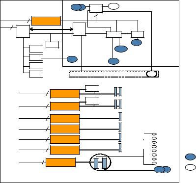
Wake on LAN Wake on LAN, a hardware feature that enables the remote power on of computers through special network packets, is enabled in core PCI/PCI-X slots one and two.
Ropes Ropes is an HP-proprietary, custom bus interface. It clocks data packets across long-lengthnetsusingsourcesynchronousclockingschemes.Thereareeighteensignalsbundled per Ropes group, of which there are a total of 16 in the rx3600. Each group is capable of 0.5GB/s peakbandwidth. Table1-1(page27) and Table1-2(page28) displaytheassociationoftheRopes group(s) to the PCI slot / HBA to which they connect.
Figure1-1(page26) isablockdiagramofthePCI/PCI-XI/Osubsystem,and Figure1-2(page27) is a block diagram of the PCI/PCI-X/PCIe I/O subsystem.
Figure 1-1 I/O Subsystem Block Diagram
|
|
USB |
USB |
USB |
Unified Core IO Board |
|||
|
|
|
|
|
|
|
|
|
Single - Rope |
|
|
|
32 bit |
|
PCI-33 |
|
|
ZX1 PCI Bridge |
|
|
|
|
|
|||
DMD |
|
USB |
|
|
|
|
||
I2C |
|
|
|
|
|
|
||
DMD |
|
BMC |
IPMB |
|
|
|
|
|
Bridge |
LPC |
|
|
RMP3 |
Video |
|
|
|
|
|
|
|
|
||||
PDH |
|
TPM |
|
|
|
VGA |
|
|
ROM |
|
|
|
|
|
|
||
|
|
|
MP LAN |
|
|
|||
|
UART |
COM |
|
|
|
|
|
|
|
|
|
|
COM |
|
|
|
|
|
|
|
|
|
|
|
|
|
|
RTC |
|
|
|
|
|
|
|
|
SRAM |
Common Display Panel board |
DVD |
|
|
|||
|
|
|
|
DHPC |
Public PHP I/O Slots |
|
|
|
Single - Rope |
|
|
|
PCIx-66 |
|
|
||
ZX1 PCI-X Bridge |
|
|
|
|
||||
|
|
|
|
|
|
|
||
Single - Rope |
|
|
DHPC |
|
PCIx-66 |
|
|
|
ZX1 PCI-X Bridge |
|
|
|
|
||||
|
|
|
|
|
|
|
||
Dual - Rope |
ZX1 PCI-X Bridge |
|
|
PCIx-133 |
|
|
||
|
|
|
|
|
||||
|
|
|
|
|
|
|
||
Dual - Rope |
ZX1 PCI-X Bridge |
|
|
PCIx-133 |
|
|
||
|
|
|
|
|
||||
|
|
|
|
|
|
|
||
Quad - Rope |
|
|
|
|
PCIx-266 |
|
|
|
ZX2 PCI-X Bridge |
|
|
|
|
|
|||
|
|
|
|
|
|
|
||
Quad - Rope |
|
|
|
|
PCIx-266 |
|
|
|
ZX2 PCI-X Bridge |
|
|
DISK BKPLN |
|
|
|||
|
|
|
|
|
|
|||
|
|
|
|
|
|
|
|
|
|
|
|
|
|
Core Disk Storage |
|
PORT |
|
Single - Rope |
|
PCIx-66 |
|
|
|
|||
ZX1 PCI-X Bridge |
ivate Slots |
|
|
|||||
|
|
|
|
|
|
Core LAN |
LAN |
PORT |
|
|
|
|
|
|
AN |
||
|
|
Common IO Board |
|
|
|
|||
Ports From
Chassis Rear
Ports From
Chassis Front
26 Overview

Figure |
1-2 |
PCI/PCI-X/PCIe I/O Subsystem Block Diagram |
|
||||||
|
|
|
|
USB |
USB |
USB Unified Core IO Board |
|||
|
|
|
|
|
|
|
|
|
|
|
|
Single - Rope |
|
|
|
32 bit |
|
PCI-33 |
|
|
|
ZX1 PCI Bridge |
|
|
|
|
|||
|
|
DMD |
|
USB |
|
|
|
||
|
|
I2C |
|
|
|
|
|
||
|
|
DMD |
BMC |
IPMB |
|
|
|
||
|
|
Bridge |
LPC |
|
|
SP |
Video |
|
|
|
|
|
|
|
|
||||
|
|
PDH |
|
TPM |
|
|
|
VGA |
|
|
|
ROM |
|
|
|
|
|
||
|
|
|
|
|
MP LAN |
|
|||
|
|
|
RTC |
UART |
|
|
|
|
|
|
|
|
|
|
|
|
|
|
|
|
|
|
|
|
|
COM |
COM |
|
|
|
|
|
SRAM |
|
|
|
|
|
|
|
|
|
|
Common Display Panel board |
|
DVD |
|||
|
|
|
|
|
|
|
Public PHP I/O Slots |
|
|
|
|
Single - Rope |
|
|
DHPC |
|
PCIx-66 |
|
|
|
|
ZX1 PCI-X Bridge |
|
|
|
|
|||
|
|
Single - Rope |
ZX1 PCI-X Bridge |
|
|
|
PCIx-133 |
|
|
|
|
|
|
|
|
|
|
|
|
|
|
Dual - Rope |
ZX1 PCI-X Bridge |
|
|
|
PCIx-133 |
|
|
|
|
|
|
|
|
|
|||
|
|
|
|
|
|
|
|
|
|
|
|
Quad - Rope |
ZX2 PCI-E Bridge |
|
|
|
X8 PCI-E |
|
|
|
|
|
|
|
|
|
|||
|
|
|
|
|
|
|
|
|
|
|
|
Quad - Rope |
ZX2 PCI-E Bridge |
|
|
|
X8 PCI-E |
|
|
|
|
|
|
|
|
|
|||
|
|
|
|
|
|
|
X8 PCI-E |
|
|
|
|
|
|
|
|
Express |
|
|
|
|
|
Dual - Rope |
ZX2 PCI-E Bridge |
|
|
DISK BKPLN |
|||
|
|
|
Switch |
|
|||||
|
|
|
|
|
|
||||
|
|
|
|
|
|
|
Core Disk Storage |
PORT |
|
|
|
Single - Rope |
|
PCIx-66 |
|
|
|||
|
|
ZX1 PCI-X Bridge |
ivate Slots |
|
|||||
|
|
|
|
|
|
|
|
Core LAN |
PORT |
|
|
|
|
|
|
|
|
LAN AN |
|
|
|
|
|
Common IO Board |
|
|
|||
Ports From
Chassis Rear
Ports From
Chassis Front
PCI/PCI-X IOBP
Onthe10slotPCI/PCI-XIOBPthereareatotal8Publicslots(PCI-Xmode1/2),2PrivateFast-core slots (PCI-X mode1), and 1 Private Slow-core UCIO slot (PCI 32-bit/33-MHz). The eight Public slots are further subdivided into three speed/bandwidth configurations:
•Four PDHP (Public Dual Hot-plug), which operate at 64-bit/66-MHz PCI-X
•Two PSHP-SDR (Public Single Hot-plug - Single Data Rate), operating at 64-bit/133-MHz PCI-X
•TwoPSHP-DDR(PublicSingleHot-plug - DoubleDataRate),at64-bit/266-MHz(133-MHz double clocked) PCI-X mode2
Four 66-MHz PCI/PCI-X slots are shared in groups of two. Shared slots have many speed and mode change restrictions during hot-plug add or remove operations. For more information on PCI/PCI-X card configuration and restrictions, see “PCI/PCI-X/PCIe Configurations” (page 62).
Four of the server PCI/PCI-X slots are not shared. Two of the nonshared slots are 133 MHz PCI/PCI-X, and two of the slots are 266-MHz PCI/PCI-X. Shared slots have many speed and mode change restrictions during hot-plug add or remove operations.
Table 1-1 PCI/PCI-X I/O Rope Groups
Slot # |
Rope Numbers |
PCI Bus |
Bits |
Speed |
Function |
Hot Swap / |
|
|
|
|
|
|
OL* |
1, 2 |
8 |
1 |
64 |
66 MHz |
Core I/O (Private) |
N |
3 |
12, 13, 14, 15 |
2 |
64 |
266 MHz |
PCI-X 2.0, DDR (Public) |
Y |
|
(Quad |
|
|
|
|
|
|
Bandwidth) |
|
|
|
|
|
4 |
4, 5, 6, 7 (Quad |
3 |
64 |
266 MHz |
PCI-X 2.0, DDR (Public) |
Y |
|
Bandwidth) |
|
|
|
|
|
5 |
10, 11 (Dual |
4 |
64 |
133 MHz |
High-Speed PCI-X (Public) |
Y |
|
Bandwidth) |
|
|
|
|
|
Server Subsystems |
27 |
Table |
1-1 PCI/PCI-X I/O Rope Groups (continued) |
|
||||
Slot # |
Rope Numbers |
PCI Bus |
Bits |
Speed |
Function |
Hot Swap / |
|
|
|
|
|
|
OL* |
6 |
2, 3 (Dual |
5 |
64 |
133 MHz |
High-Speed PCI-X (Public) |
Y |
|
Bandwidth) |
|
|
|
|
|
7, 8 |
9 |
6 |
64 |
66 MHz |
General PCI-X (Public) |
Y |
9, 10 |
1 |
7 |
64 |
66 MHz |
General PCI-X (Public) |
Y |
- |
0 |
0 |
32 |
33 MHz |
UCIO (Private) |
N |
PCI/PCI-X/PCIe IOBP
On the 10 slot PCI/PCI-X/PCIe IOBP there are a total of eight Public slots (four PCI-X mode 1 and four PCIe), two Private Fast-core slots (PCI/PCI-X mode 1 64-bit/66-MHz), and one Private Slow-core UCIO slot (PCI 32-bit/33-MHz). The eight Public slots are further divided into three speed/bandwidth configurations:
•Two PDHP, which operate at 64-bit/66-MHz PCI-X
•Two PSHP, operating at 64-bit/133-MHz PCI-X
•Four PCIe 8-lane (x8) 2.5 Gbps, two of which are switched
The two 66 MHz PCI/PCI-X slots are shared. Shared slots have many speed and mode change restrictions during hot-plug add or remove operations.
Table |
1-2 PCI/PCI-X/PCIe I/O Rope Groups |
|
|
||
Slot # |
Rope Numbers |
Bits |
Speed |
Function |
Hot Swap/OLR |
1, 2 |
8 |
64 |
66 MHz |
Core I/O (Private) |
N |
3, 4 |
10, 11 |
x8 |
2.5 Gbps |
PCIex8(PublicorPrivatedependingupon |
N |
|
|
|
|
Core I/O) |
|
5 |
12, 13, 14, 15 |
x8 |
2.5 Gbps |
PCIe x8 (Public) |
Y |
6 |
4, 5, 6, 7 |
x8 |
2.5 Gbps |
PCIe x8 (Public) |
Y |
7 |
2, 3 |
64 |
133 MHz |
High-Speed PCI-X (Public) |
Y |
8 |
9 |
64 |
133 MHz |
High-Speed PCI-X (Public) |
Y |
9, 10 |
1 |
64 |
66 MHz |
General PCI-X (Public) |
Y |
- |
0 |
32 |
33 MHz |
UCIO (Private) |
N |
PCIe MPS Optimization
For PCIe-based systems, each PCIe device has a configurable MPS (maximum payload size) parameter. Larger MPS values can enable the optimization to gain higher performance.MPS Optimization is supported on PCIe systems running HP-UX, Open VMS, and Linux. System firmware level greater than 02.03 performs an optimization during boot time to set the MPS value to the largest size supported by both a PCIe root port and the devices below it.
The default server state is optimization disabled. When disabled system firmware sets MPS to the minimum value on each PCIe device.
The info io command will display the current PCIe MPS optimization setting. See “info” (page 328).
ToenablePCIeMPSoptimizationusetheioconfig mps_optimize command.See“ioconfig” (page 326).
For non-PCIe systems, ioconfig and info io will not display the MPS optimization policy setting.TheSet PCIe MPS Optimization bootmanagermenualsowillnotbedisplayed.Running
28 Overview
the ioconfig mps_optimize [on|off] command from a non-PCIe system, the following output will be displayed:
-------------
Shell> ioconfig mps_optimize
ioconfig: PCIe MPS optimization is not supported.
Shell> ioconfig mps_optimize on
ioconfig: PCIe MPS optimization is not supported. Exit status code: Unsupported
Shell>
-----------------
TorestoreMPStothedefaultvaluesusethedefault clear command.See“default”(page327).
Processor
Theserverprocessorsubsystemaccommodatesoneortwodual-coreItanium®processormodules. The processor subsystem consists of the following elements:
•zx2 CEC front side bus, memory, and I/O controller
•System clock generation and distribution
•Circuitry for manageability and fault detection
The zx2 CEC and the processor modules are located on the processor board assembly. Each processorconnectstotheprocessorboardthroughazeroinsertionforce(ZIF)socket.Theprocessor boardismountedonaremovablecarriertraythatisattachedtotheprocessorboardaccessdoor. Access the assembly through the front of the server after the memory carrier is removed.
Memory
The server DIMMS are seated on memory boards that are enclosed in an extractable memory carrier assembly. The memory boards plug directly into sockets on the processor board when the memory carrier assembly is fully seated.
Table 1-3 lists the two types of supported memory carriers and the memory configurations of each carrier.
Table 1-3 Supported Memory Configurations
Memory Carrier Type |
Memory Boards Installed |
Minimum Memory |
Maximum Memory |
|
|
Configuration |
Configuration |
8-DIMM memory carrier |
Two 4-DIMM memory |
2-GB (one pair: two 1-GB |
32-GB (eight 4-GB DIMMs) |
(standard) |
boards |
DIMMs) |
|
24-DIMM memory carrier |
Two 12-DIMM memory |
2-GB (one quad: four |
96-GB (24x4-GB DIMMs) |
(optional, high-capacity) |
boards |
512-MB DIMMs) |
|
The server supports the following DIMM sizes:
•512-MB
•1-GB
•2-GB
•4-GB
Figure 1-3 is a block diagram of the 8-DIMM memory carrier that shows data, addresses, and controls that flow through the CEC and to and from the processors.
Server Subsystems |
29 |
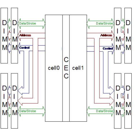
Figure 1-3 8-DIMM Memory Carrier Block Diagram
Figure 1-4 is a block diagram of the 24-DIMM memory carrier that shows data, addresses, and controls that flow from the processors through the CEC and memory mux to the DIMMs.
30 Overview
Loading...