


 Loading...
HP 9000 rp3410 and HP 9000 rp3440
User Service Guide
HP Part Number: A7137-96008-ed6
Published: February 2010
Edition: 6
Legal Notices
Copyright©2003,2010Hewlett-PackardDevelopmentCompany,L.P. Theinformationcontainedhereinissubjecttochangewithoutnotice. The onlywarrantiesforHPproductsandservicesaresetforthintheexpresswarrantystatementsaccompanyingsuchproductsandservices.Nothing herein should be construed as constituting an additional warranty. HP shall not be liable for technical or editorial errors or omissions contained herein. Intel, Pentium, Intel Inside, and the Intel Inside logo are trademarks or registered trademarks of Intel Corporation or its subsidiaries in the United States and other countries.
Warranty
To obtain a copy of the warranty for this product, see the warranty information website:
BCS Global Limited Warranty and Technical Support

Table of Contents |
|
About This Document....................................................................................................... |
15 |
Intended Audience................................................................................................................................ |
15 |
New and Changed Information in This Edition................................................................................... |
15 |
Publishing History................................................................................................................................ |
15 |
Document Organization....................................................................................................................... |
15 |
Typographic Conventions..................................................................................................................... |
16 |
HP-UX Release Name and Release Identifier....................................................................................... |
16 |
Related Documents............................................................................................................................... |
17 |
Contacting HP....................................................................................................................................... |
17 |
Before You Contact HP.................................................................................................................... |
17 |
HP Contact Information.................................................................................................................. |
18 |
Subscription Service........................................................................................................................ |
18 |
Documentation Feedback................................................................................................................ |
18 |
1 Overview....................................................................................................................... |
19 |
HP 9000 rp3410 and rp3440 Server Views............................................................................................ |
19 |
Detailed Server Description.................................................................................................................. |
20 |
Processor.......................................................................................................................................... |
20 |
Memory........................................................................................................................................... |
20 |
PCI Riser.......................................................................................................................................... |
21 |
Internal Core I/O.............................................................................................................................. |
21 |
External Core I/O............................................................................................................................. |
21 |
Power Supply Unit.......................................................................................................................... |
21 |
System Board Manageability........................................................................................................... |
22 |
Enhanced Server Manageability Using the iLO MP........................................................................ |
22 |
Hard Disk Drives............................................................................................................................. |
22 |
Internal RAID.................................................................................................................................. |
22 |
Firmware.......................................................................................................................................... |
22 |
Event IDs for Errors and Events................................................................................................. |
23 |
Dimensions and Values................................................................................................................... |
23 |
System Board................................................................................................................................... |
23 |
System Board Components........................................................................................................ |
24 |
PA RISC Processor...................................................................................................................... |
24 |
Processor Bus.............................................................................................................................. |
25 |
ZX1 I/O and Memory Controller................................................................................................ |
25 |
Memory...................................................................................................................................... |
25 |
Memory Architecture............................................................................................................ |
26 |
Chip Spare Functionality...................................................................................................... |
27 |
Serial Presence Detect........................................................................................................... |
27 |
I/O Bus Interface......................................................................................................................... |
27 |
Processor Dependent Hardware Controller.............................................................................. |
27 |
Field Programmable Gate Array................................................................................................ |
28 |
BMC............................................................................................................................................ |
28 |
SCSI Controller........................................................................................................................... |
28 |
IDE Interface............................................................................................................................... |
29 |
1 GB System LAN....................................................................................................................... |
29 |
USB Connectors.......................................................................................................................... |
29 |
Disk and I/O Path Logging......................................................................................................... |
29 |
Controls, Ports, and LEDs..................................................................................................................... |
31 |
Control Panel................................................................................................................................... |
31 |
Table of Contents |
3 |
Additional Controls and Indicators................................................................................................ |
33 |
Hot-Pluggable Disk Drive Indicators......................................................................................... |
33 |
Optional Removable Media Drive............................................................................................. |
33 |
Rear Panel........................................................................................................................................ |
34 |
10/100/1000 Base-T Ethernet LAN Connector............................................................................ |
35 |
USB Ports.................................................................................................................................... |
35 |
SCSI Port, Ultra 3, 68-Pin............................................................................................................ |
36 |
iLO MP Card LAN LEDs........................................................................................................... |
37 |
Powering the Server On and Off........................................................................................................... |
38 |
Power States..................................................................................................................................... |
38 |
Powering On the Server................................................................................................................... |
39 |
Powering On the Server Using the iLO MP............................................................................... |
39 |
Powering On the Server Manually............................................................................................. |
39 |
Powering Off the Server.................................................................................................................. |
39 |
Powering Off the Server Using the iLO MP............................................................................... |
39 |
Powering Off the Server Manually............................................................................................ |
40 |
2 System Specifications................................................................................................... |
41 |
System Configuration........................................................................................................................... |
41 |
Dimensions and Values......................................................................................................................... |
41 |
Grounding............................................................................................................................................. |
42 |
Electrical Specifications......................................................................................................................... |
42 |
AC Power Cables............................................................................................................................. |
42 |
Circuit Breaker................................................................................................................................. |
42 |
System Power Specifications........................................................................................................... |
43 |
Power and Cooling.......................................................................................................................... |
43 |
Environmental Specifications............................................................................................................... |
44 |
Operating Environment................................................................................................................... |
44 |
Environmental Temperature Sensor................................................................................................ |
45 |
Nonoperating Environment............................................................................................................ |
45 |
Cooling............................................................................................................................................. |
45 |
CPU and Memory Cooling......................................................................................................... |
45 |
Bulk Power Supply Cooling....................................................................................................... |
45 |
PCI and Mass Storage Section Cooling...................................................................................... |
45 |
Acoustic Noise Specification........................................................................................................... |
46 |
Physical and Environmental Specifications.......................................................................................... |
46 |
3 Installing the System..................................................................................................... |
47 |
Introduction.......................................................................................................................................... |
47 |
Server Views.................................................................................................................................... |
47 |
Detailed Server Description............................................................................................................. |
48 |
Features...................................................................................................................................... |
48 |
Firmware.................................................................................................................................... |
49 |
Event IDs for Errors and Events........................................................................................... |
49 |
Dimensions and Values.............................................................................................................. |
49 |
Safety Information........................................................................................................................... |
50 |
Installation Sequence and Checklist................................................................................................ |
50 |
Unpacking and Inspecting the Server................................................................................................... |
51 |
Verifying Site Preparation............................................................................................................... |
51 |
Inspecting the Shipping Containers for Damage............................................................................ |
51 |
Unpacking the Server...................................................................................................................... |
51 |
Checking the Inventory................................................................................................................... |
51 |
Returning Damaged Equipment..................................................................................................... |
52 |
4Table of Contents
Unloading the Server with a Lifter.................................................................................................. |
52 |
Installing Additional Components....................................................................................................... |
52 |
Removing and Replacing Server Covers and Bezels....................................................................... |
52 |
Rack-Mounted Server................................................................................................................. |
52 |
Accessing a Rack-Mounted Server....................................................................................... |
52 |
Extend the Server From the Rack.......................................................................................... |
53 |
Removing and Replacing the Top Cover on a Rack-Mounted Server.................................. |
53 |
Removing and Replacing the Front Bezel on a Rack-Mounted Server................................ |
55 |
Accessing a Pedestal-Mounted Server....................................................................................... |
57 |
Removing the Side Cover on a Pedestal-Mounted Server.................................................... |
57 |
Removing the Top Cover on Pedestal-Mounted Server....................................................... |
57 |
Replacing the Top Cover on a Pedestal-Mounted Server..................................................... |
58 |
Replacing the Side Cover on a Pedestal-Mounted Server.................................................... |
59 |
Removing and Replacing the Front Bezel on a Pedestal-Mounted Server........................... |
60 |
Installing Internal Hard Disk Drives............................................................................................... |
61 |
Installing a DVD Drive.................................................................................................................... |
64 |
Installing the DVD Drive........................................................................................................... |
64 |
Removing and Replacing Airflow Guides...................................................................................... |
65 |
Removing and Replacing the Memory Airflow Guide.............................................................. |
65 |
Removing the Memory Airflow Guide................................................................................. |
65 |
Replacing the Memory Airflow Guide................................................................................. |
66 |
Removing and Replacing the Processor Airflow Guide............................................................ |
66 |
Removing the Processor Airflow Guide............................................................................... |
66 |
Replacing the Processor Airflow Guide............................................................................... |
69 |
Installing Additional System Memory............................................................................................ |
70 |
Supported DIMM Sizes.............................................................................................................. |
70 |
Installing System Memory......................................................................................................... |
71 |
rp3410 Memory Configuration............................................................................................. |
71 |
Memory Loading Rules and Performance Guidelines......................................................... |
72 |
rp3440 Memory Configuration............................................................................................. |
72 |
Memory Loading Rules and Performance Guidelines......................................................... |
72 |
System Firmware Requirements........................................................................................... |
72 |
Installation Procedure........................................................................................................... |
73 |
Removing and Replacing the PCI Card Cage................................................................................. |
74 |
Removing the PCI Card Cage.................................................................................................... |
74 |
Replacing the PCI Card Cage..................................................................................................... |
75 |
Installing PCI Cards......................................................................................................................... |
75 |
Installing a PCI Card.................................................................................................................. |
76 |
Installing an Additional Power Supply........................................................................................... |
76 |
Installing an Additional Processor Module.................................................................................... |
78 |
Replacing the System Battery.......................................................................................................... |
85 |
Battery Notice............................................................................................................................. |
85 |
Replacing the System Battery..................................................................................................... |
85 |
Installing the Server Into a Rack, Non-HP Rack, or Pedestal............................................................... |
86 |
HP Rack........................................................................................................................................... |
87 |
Non-HP Rack................................................................................................................................... |
87 |
Pedestal Mount................................................................................................................................ |
87 |
Connecting the Cables.......................................................................................................................... |
87 |
AC Input Power............................................................................................................................... |
87 |
Core I/O Connections...................................................................................................................... |
87 |
Applying Standby Power To the Server.......................................................................................... |
88 |
Connecting To the LAN................................................................................................................... |
88 |
Console Setup....................................................................................................................................... |
89 |
Setup Checklist................................................................................................................................ |
89 |
Setup Flowchart............................................................................................................................... |
90 |
Table of Contents |
5 |
Preparation...................................................................................................................................... |
91 |
Determining the Physical iLO MP Access Method.................................................................... |
91 |
Determining the iLO MP LAN Configuration Method............................................................. |
92 |
Configuring the iLO MP LAN Using DHCP and DNS................................................................... |
92 |
Configuring the iLO MP LAN Using ARP Ping............................................................................. |
93 |
Configuring the iLO MP LAN Using the RS-232 Serial Port.......................................................... |
94 |
Logging In to the iLO MP................................................................................................................ |
95 |
Additional Setup.............................................................................................................................. |
96 |
Modifying User Accounts and Default Password..................................................................... |
96 |
Setting Up Security..................................................................................................................... |
97 |
Security Access Settings........................................................................................................ |
97 |
Accessing the Host Console.................................................................................................................. |
97 |
Accessing the Host Console With the TUI - CO Command............................................................ |
97 |
Interacting With the iLO MP Using the Web GUI........................................................................... |
98 |
Accessing the Graphic Console Using VGA................................................................................... |
99 |
Enabling VGA Graphics Capability........................................................................................... |
99 |
Installing Your A6150B Graphics Card.................................................................................... |
100 |
Connecting a Monitor Using the VGA Port............................................................................. |
100 |
Powering the Server ON and OFF...................................................................................................... |
100 |
Power States................................................................................................................................... |
100 |
Powering On the Server................................................................................................................. |
101 |
Powering On the Server Using the iLO MP PC Command..................................................... |
101 |
Powering On the Server Manually........................................................................................... |
101 |
Powering Off the Server................................................................................................................. |
101 |
Powering Off the Server Using the iLO MP PC Command..................................................... |
102 |
Powering Off the Server Manually........................................................................................... |
102 |
Booting the Operating System............................................................................................................ |
102 |
Supported Operating System........................................................................................................ |
102 |
Booting and Shutting Down HP-UX............................................................................................. |
102 |
Standard HP-UX Booting Using the Boot Console Handler.................................................... |
102 |
Booting HP-UX in Single-User Mode....................................................................................... |
103 |
Booting HP-UX in LVM Maintenance Mode............................................................................ |
103 |
Shutting Down HP-UX............................................................................................................. |
103 |
Verifying the Server Configuration Using Boot Console Handler................................................ |
104 |
Troubleshooting.................................................................................................................................. |
104 |
Troubleshooting Methodology...................................................................................................... |
104 |
Troubleshooting Using the Server Power Button.......................................................................... |
104 |
Server Does Not Power On............................................................................................................ |
105 |
Operating System Does Not Boot.................................................................................................. |
105 |
Operating System Boots with Problems........................................................................................ |
106 |
Intermittent Server Problems......................................................................................................... |
106 |
DVD Problems............................................................................................................................... |
106 |
Hard Drive Problems..................................................................................................................... |
106 |
Console Problems.......................................................................................................................... |
106 |
Downloading and Installing the Latest Version of the Firmware................................................. |
106 |
Downloading the Latest Version of the Firmware................................................................... |
107 |
Installing the Latest Version of the Firmware.......................................................................... |
107 |
Troubleshooting Using LED Indicators......................................................................................... |
107 |
Front Control Panel LEDs........................................................................................................ |
107 |
Information to Collect Before You Contact Support...................................................................... |
108 |
4 Booting the Operating System................................................................................. |
109 |
Supported Operating System.............................................................................................................. |
109 |
Booting and Shutting Down HP-UX................................................................................................... |
109 |
6Table of Contents
Standard HP-UX Booting Using the Boot Console Handler......................................................... |
109 |
Booting HP-UX in Single-User Mode............................................................................................ |
110 |
Booting HP-UX in LVM Maintenance Mode................................................................................. |
110 |
Shutting Down HP-UX.................................................................................................................. |
110 |
Verifying the Server Configuration Using Boot Console Handler..................................................... |
111 |
5 Troubleshooting.......................................................................................................... |
113 |
Troubleshooting Methodology........................................................................................................... |
113 |
Troubleshooting System Power.......................................................................................................... |
113 |
Using the Front Panel Power Button............................................................................................. |
113 |
Operating System Does Boot......................................................................................................... |
114 |
Operating System Does Not Boot.................................................................................................. |
114 |
Troubleshooting Using Online Support Tools.................................................................................... |
114 |
Support Tools Manager................................................................................................................. |
114 |
Event Monitoring Service.............................................................................................................. |
114 |
iLO MP........................................................................................................................................... |
115 |
Accessing the iLO MP Interface and System Logs................................................................... |
115 |
SEL....................................................................................................................................... |
115 |
Troubleshooting Using Offline Support Tools.................................................................................... |
116 |
Offline Diagnostic Environment.................................................................................................... |
116 |
Identifying and Diagnosing Hardware Problems.............................................................................. |
117 |
Troubleshooting Using LEDs.............................................................................................................. |
117 |
Power and System LEDs................................................................................................................ |
118 |
LAN LEDs...................................................................................................................................... |
118 |
System Board LEDs....................................................................................................................... |
119 |
Cleaning Procedures........................................................................................................................... |
120 |
6 Removing and Replacing Components................................................................... |
123 |
Safety Information............................................................................................................................... |
123 |
Required Service Tools........................................................................................................................ |
123 |
Location of Internal Components and Connectors............................................................................. |
123 |
Removing and Replacing Server Covers and Bezel............................................................................ |
126 |
Accessing a Rack-Mount Server.................................................................................................... |
126 |
Extending the Server From the Rack........................................................................................ |
126 |
Inserting the Server Into the Rack............................................................................................ |
127 |
Removing and Replacing the Top Cover on a Rack-Mounted Server..................................... |
127 |
Removing the Top Cover on a Rack-Mounted Server........................................................ |
127 |
Replacing the Top Cover on a Rack-Mounted Server......................................................... |
128 |
Removing and Replacing the Front Bezel on a Rack-Mounted Server.................................... |
129 |
Removing the Front Bezel................................................................................................... |
129 |
Replacing the Front Bezel................................................................................................... |
129 |
Accessing a Pedestal-Mount Server............................................................................................... |
130 |
Removing the Side Covers on a Pedestal-Mounted Server...................................................... |
130 |
Replacing the Top and Side Covers on a Pedestal-Mounted Server................................... |
132 |
Removing and Replacing the Front Bezel on a Pedestal-Mounted Server......................... |
134 |
Removing and Replacing System Fans............................................................................................... |
136 |
Removing a System Fan................................................................................................................. |
136 |
Replacing a System Fan................................................................................................................. |
138 |
Removing and Replacing the Power Supply...................................................................................... |
138 |
Removing the Power Supply......................................................................................................... |
138 |
Replacing the Power Supply.......................................................................................................... |
139 |
Removing and Replacing an Internal Hard Disk Drive..................................................................... |
140 |
Removing a Hard Disk Drive........................................................................................................ |
140 |
Table of Contents |
7 |
Replacing a Hard Disk Drive......................................................................................................... |
142 |
Removing and Replacing Airflow Guides.......................................................................................... |
144 |
Removing and Replacing the Memory Airflow Guide................................................................. |
144 |
Removing the Memory Airflow Guide.................................................................................... |
144 |
Replacing the Memory Airflow Guide..................................................................................... |
145 |
Removing and Replacing the Processor Airflow Guide................................................................ |
145 |
Removing the Processor Airflow Guide.................................................................................. |
145 |
Replacing the Processor Airflow Guide................................................................................... |
148 |
Removing and Replacing System Memory........................................................................................ |
149 |
Supported DIMM Sizes................................................................................................................. |
149 |
rp3410 Memory Configuration...................................................................................................... |
150 |
Memory Loading Rules............................................................................................................ |
151 |
rp3440 Memory Configuration...................................................................................................... |
151 |
Memory Loading Rules............................................................................................................ |
151 |
System Firmware Requirements.................................................................................................... |
151 |
Replacing Deallocated Memory Ranks.......................................................................................... |
151 |
Removing System Memory........................................................................................................... |
152 |
Installing System Memory............................................................................................................. |
152 |
Removing and Replacing a Dual Processor Module.......................................................................... |
155 |
Removing a Dual Processor Module............................................................................................. |
155 |
Installing a Dual Processor Module.............................................................................................. |
160 |
Removing and Replacing the System Battery..................................................................................... |
165 |
Battery Notice................................................................................................................................ |
165 |
Removing the System Battery........................................................................................................ |
165 |
Replacing the System Battery........................................................................................................ |
166 |
Removing and Replacing the PCI Card Cage..................................................................................... |
167 |
Removing the PCI Card Cage........................................................................................................ |
167 |
Replacing the PCI Card Cage........................................................................................................ |
168 |
Removing and Replacing PCI Cards.................................................................................................. |
169 |
Removing a PCI or Graphics Card................................................................................................ |
169 |
Replacing a PCI or Graphics Card................................................................................................. |
170 |
Removing and Replacing the PCI Backplane..................................................................................... |
171 |
Removing the PCI Backplane........................................................................................................ |
171 |
Replacing the PCI Backplane......................................................................................................... |
171 |
Removing and Replacing a Removable Media Drive......................................................................... |
172 |
Removing a Removable Media Drive............................................................................................ |
172 |
Replacing a Removable Media Drive............................................................................................ |
173 |
Removing and Replacing the iLO MP Card....................................................................................... |
173 |
Removing the iLO MP Card.......................................................................................................... |
173 |
Replacing the iLO MP Card........................................................................................................... |
174 |
Removing and Replacing the iLO MP Card Battery........................................................................... |
175 |
Battery Notice................................................................................................................................ |
175 |
Removing the iLO MP Card Battery............................................................................................. |
175 |
Replacing the iLO MP Card Battery.............................................................................................. |
176 |
Removing and Replacing the LED Status Panel................................................................................. |
176 |
Removing the LED Status Panel.................................................................................................... |
176 |
Replacing the LED Status Panel..................................................................................................... |
177 |
Removing and Replacing the System Board....................................................................................... |
177 |
Removing the System Board.......................................................................................................... |
177 |
Replacing the System Board.......................................................................................................... |
180 |
Replacing the Resident System Board with a Replacement System Board........................................ |
184 |
Replacing a System Board............................................................................................................. |
185 |
Removing and Replacing the Power Supply Interface Module......................................................... |
186 |
Removing the Power Supply Interface Module............................................................................ |
186 |
Replacing the Power Supply Interface Module............................................................................. |
187 |
8Table of Contents
Removing and Replacing the Hard Disk Drive (SCSI) Backplane |
.....................................................189 |
Removing the Hard Drive Disk SCSI Backplane........................................................................... |
189 |
Replacing the Hard Disk Drive SCSI Backplane........................................................................... |
191 |
A Replacement Parts..................................................................................................... |
193 |
Parts Illustrations................................................................................................................................ |
193 |
Customer Self Repair.......................................................................................................................... |
194 |
Replaceable Parts List.......................................................................................................................... |
195 |
B Utilities......................................................................................................................... |
199 |
Boot Console Handler......................................................................................................................... |
199 |
BCH Commands............................................................................................................................ |
199 |
BCH Main Menu Commands and Submenus.......................................................................... |
200 |
Boot Command................................................................................................................... |
200 |
Path Command................................................................................................................... |
200 |
Search Command................................................................................................................ |
201 |
Configuration Menu................................................................................................................. |
201 |
Information Menu.................................................................................................................... |
202 |
Service Menu............................................................................................................................ |
203 |
Display Command................................................................................................................... |
203 |
SCSI Command........................................................................................................................ |
203 |
ProductNum Command........................................................................................................... |
203 |
iLO MP................................................................................................................................................ |
203 |
C Physical and Environmental Specifications............................................................. |
205 |
Index............................................................................................................................... |
207 |
Table of Contents |
9 |

List of Figures
1-1 |
HP 9000 rp3410 and rp3440 Servers - Front View......................................................................... |
19 |
1-2 |
HP 9000 rp3410 and rp3440 Servers - Front View with Bezel Removed...................................... |
19 |
1-3 |
HP 9000 rp3410 and rp3440 Servers - Rear View.......................................................................... |
19 |
1-4 |
HP 9000 rp3410 and rp3440 Servers - Pedestal Mount.................................................................. |
20 |
1-5 |
System Board Block Diagram........................................................................................................ |
24 |
1-6 |
Memory Block Diagram................................................................................................................ |
26 |
1-7 |
Front View..................................................................................................................................... |
31 |
1-8 |
Control Panel LEDs and Buttons................................................................................................... |
32 |
1-9 |
Hot-Pluggable Disk Drive LED Indicators.................................................................................... |
33 |
1-10 |
DVD Drive..................................................................................................................................... |
33 |
1-11 |
Rear View...................................................................................................................................... |
34 |
1-12 |
10/100/1000 Base-T Ethernet LAN Connector LEDs..................................................................... |
35 |
1-13 |
Dual USB Port Connector.............................................................................................................. |
36 |
1-14 |
Single USB Port.............................................................................................................................. |
36 |
1-15 |
SCSI Port, Ultra 3, 68-Pin............................................................................................................... |
36 |
1-16 |
iLO MP Card LAN LEDs............................................................................................................... |
38 |
3-1 |
HP 9000 rp3410/rp3440 Server - Front View................................................................................. |
47 |
3-2 |
HP 9000 rp3410/rp3440 Server - Front View with Bezel Removed............................................... |
47 |
3-3 |
HP 9000 rp3410/rp3440 Server - Rear View................................................................................... |
47 |
3-4 |
HP 9000 rp3410/rp3440 Server - Pedestal Mount.......................................................................... |
48 |
3-5 |
Release the Rack Latches............................................................................................................... |
53 |
3-6 |
Removing and Replacing the Top Cover on a Rack-Mounted Server.......................................... |
54 |
3-7 |
Aligning the Top Cover................................................................................................................. |
55 |
3-8 |
Closing the Top Cover................................................................................................................... |
55 |
3-9 |
Front Bezel Retaining Clip............................................................................................................ |
56 |
3-10 |
Replacing the Front Bezel.............................................................................................................. |
56 |
3-11 |
Removing the Side Cover on a Pedestal-Mounted Server............................................................ |
57 |
3-12 |
Removing the Top Cover on a Pedestal-Mounted Server............................................................. |
58 |
3-13 |
Top Cover Alignment Mark.......................................................................................................... |
58 |
3-14 |
Replacing the Top Cover on a Pedestal-Mounted Server.............................................................. |
59 |
3-15 |
Replacing the Side Cover on a Pedestal-Mounted Server............................................................. |
59 |
3-16 |
Removing the Front Bezel on a Pedestal-Mounted Server............................................................ |
60 |
3-17 |
Aligning the Pedestal Front Bezel................................................................................................. |
61 |
3-18 |
Front View of the HP 9000 rp3410/rp3440 Server......................................................................... |
61 |
3-19 |
Filler Removal from Slot 1............................................................................................................. |
62 |
3-20 |
Disk Drive Installation in Slot 3..................................................................................................... |
62 |
3-21 |
Hard Drive Lock............................................................................................................................ |
63 |
3-22 |
DVD Drive Installation.................................................................................................................. |
64 |
3-23 |
Airflow Guides Locations............................................................................................................. |
65 |
3-24 |
Removing the Memory Airflow Guide......................................................................................... |
66 |
3-25 |
Removing the Processor Airflow Guide....................................................................................... |
67 |
3-26 |
Removing Fans 1A and 1B............................................................................................................ |
67 |
3-27 |
Opening the Release Clip.............................................................................................................. |
68 |
3-28 |
Removing the Front Portion of the Processor Airflow Guide....................................................... |
68 |
3-29 |
Routing the Turbofan Power Cables Through Heatsink Posts..................................................... |
69 |
3-30 |
DIMM Slot Identification.............................................................................................................. |
71 |
3-31 |
Inserting the DIMM Into the Connector....................................................................................... |
73 |
3-32 |
Removing the PCI Card Cage....................................................................................................... |
74 |
3-33 |
Removing the PCI Card Cage Cover............................................................................................. |
75 |
3-34 |
Installing a PCI Card..................................................................................................................... |
76 |
3-35 |
Removing the Power Supply Filler Panel...................................................................................... |
77 |
3-36 |
Replacing the Power Supply......................................................................................................... |
77 |
10 List of Figures
3-37 |
Unlocking the Dual Processor Module Locking Mechanism....................................................... |
79 |
3-38 |
Aligning the Processor Module..................................................................................................... |
80 |
3-39 |
Locking the Dual Processor Module in Place................................................................................ |
80 |
3-40 |
Sliding the Sequencing Retainer Plate........................................................................................... |
81 |
3-41 |
Securing the Captive Screws......................................................................................................... |
81 |
3-42 |
Power Module Shims.................................................................................................................... |
82 |
3-43 |
Aligning the Processor Module Power Pod.................................................................................. |
82 |
3-44 |
Installing the Processor Module Power Pod Mounting Screws.................................................... |
83 |
3-45 |
Connecting the Power Pod Cable.................................................................................................. |
84 |
3-46 |
Routing the Turbofan Power Cables through Heatsink Posts...................................................... |
84 |
3-47 |
Replacing the System Battery........................................................................................................ |
86 |
3-48 |
LAN Ports on the Server Rear....................................................................................................... |
89 |
3-49 |
iLO MP Setup Flowchart............................................................................................................... |
91 |
3-50 |
Web GUI Login Page..................................................................................................................... |
98 |
3-51 |
Status Summary Page.................................................................................................................... |
99 |
3-52 |
Control Panel LEDs and Buttons................................................................................................. |
107 |
5-1 |
Control Panel LEDs..................................................................................................................... |
118 |
5-2 |
Location of the STBY and BMC LEDs......................................................................................... |
120 |
6-1 |
Internal Physical Layout.............................................................................................................. |
124 |
6-2 |
System Board Connectors and Slots............................................................................................ |
125 |
6-3 |
Release the Rack Latches............................................................................................................. |
127 |
6-4 |
Removing the Top Cover on a Rack-Mounted Server................................................................. |
128 |
6-5 |
Aligning the Top Cover on a Rack-Mounted Server................................................................... |
128 |
6-6 |
Closing the Top Cover on a Rack-Mounted Server..................................................................... |
129 |
6-7 |
Front Bezel Retaining Clip........................................................................................................... |
129 |
6-8 |
Replacing the Front Bezel on a Rack-Mounted Server................................................................ |
130 |
6-9 |
Removing the Side Cover on a Pedestal-Mounted Server.......................................................... |
131 |
6-10 |
Removing the Top Cover on a Pedestal-Mounted Server........................................................... |
132 |
6-11 |
Top Cover Alignment Mark........................................................................................................ |
133 |
6-12 |
Replacing the Top Cover on a Pedestal-Mounted Server............................................................ |
133 |
6-13 |
Replacing the Side Cover on a Pedestal-Mounted Server........................................................... |
134 |
6-14 |
Removing the Front Bezel on a Pedestal-Mounted Server.......................................................... |
135 |
6-15 |
Aligning the Pedestal Front Bezel............................................................................................... |
135 |
6-16 |
Removing Fan 1A or Fan 1B........................................................................................................ |
137 |
6-17 |
Removing Fan 2........................................................................................................................... |
137 |
6-18 |
Removing Fan 3........................................................................................................................... |
137 |
6-19 |
Releasing the Power Supply Retaining Clip................................................................................ |
139 |
6-20 |
Removing the Power Supply....................................................................................................... |
139 |
6-21 |
Replacing the Power Supply....................................................................................................... |
140 |
6-22 |
Unlocking the Disk Drive............................................................................................................ |
141 |
6-23 |
Releasing the Disk Drive............................................................................................................. |
141 |
6-24 |
Removing the Disk Drive............................................................................................................ |
142 |
6-25 |
Removing the Disk Drive Slot Filler............................................................................................ |
143 |
6-26 |
Installing the Hard Disk Drive.................................................................................................... |
143 |
6-27 |
Airflow Guides Locations............................................................................................................ |
144 |
6-28 |
Removing the Memory Airflow Guide....................................................................................... |
145 |
6-29 |
Removing the Processor Airflow Guide...................................................................................... |
146 |
6-30 |
Opening the Release Clip............................................................................................................ |
147 |
6-31 |
Removing the Front Portion of the Processor Airflow Guide .................................................... |
147 |
6-32 |
Routing Power Cables Through Heatsink Posts......................................................................... |
149 |
6-33 |
DIMM Slot Identification............................................................................................................. |
150 |
6-34 |
Inserting the DIMM Into the Connector Socket.......................................................................... |
154 |
6-35 |
Disconnecting the Power Pod Cable............................................................................................ |
155 |
6-36 |
Removing the Power Pod Mounting Screws............................................................................... |
156 |
6-37 |
Disconnecting the Power Pod From the Dual Processor Module............................................... |
156 |
11
6-38 |
Removing the Power Pod............................................................................................................ |
157 |
6-39 |
Disconnecting the Turbo Fan Cable............................................................................................. |
157 |
6-40 |
Releasing the Heatsink Captive Screws...................................................................................... |
158 |
6-41 |
Unlocking the Dual Processor Module Locking Mechanism...................................................... |
158 |
6-42 |
Removing the Dual Processor Module........................................................................................ |
159 |
6-43 |
Dual Processor Module Location on System Board.................................................................... |
159 |
6-44 |
Unlocking the Dual Processor Module Locking Mechanism...................................................... |
160 |
6-45 |
Aligning the Dual Processor Module.......................................................................................... |
161 |
6-46 |
Locking the Dual Processor Module in Place.............................................................................. |
161 |
6-47 |
Securing the Captive Screws....................................................................................................... |
162 |
6-48 |
Power Module Shims................................................................................................................... |
162 |
6-49 |
Aligning the Processor Module Power Pod................................................................................ |
163 |
6-50 |
Installing the Processor Module Power Pod Mounting Screws.................................................. |
164 |
6-51 |
Routing the Turbofan Power Cables Through the Heatsink Posts.............................................. |
164 |
6-52 |
Connecting the Power Pod Cable................................................................................................ |
165 |
6-53 |
Removing the System Battery..................................................................................................... |
166 |
6-54 |
Removing the PCI Card Cage...................................................................................................... |
168 |
6-55 |
Removing the PCI Card Cage Cover........................................................................................... |
168 |
6-56 |
Installing a PCI Slot Cover........................................................................................................... |
170 |
6-57 |
Installing a PCI Card................................................................................................................... |
170 |
6-58 |
Removing the PCI Backplane...................................................................................................... |
171 |
6-59 |
Replacing the PCI Backplane....................................................................................................... |
172 |
6-60 |
Removing the Removable Media Drive...................................................................................... |
173 |
6-61 |
Removing the iLO MP card......................................................................................................... |
174 |
6-62 |
Removing the iLO MP Card Battery........................................................................................... |
176 |
6-63 |
Removing the LED Status Panel.................................................................................................. |
177 |
6-64 |
Removing the Mechanical Covers............................................................................................... |
178 |
6-65 |
Removing the Backplane System Board Mounting Screws........................................................ |
178 |
6-66 |
Removing the System Board Mounting Screw........................................................................... |
179 |
6-67 |
Removing the System Board....................................................................................................... |
180 |
6-68 |
Aligning the System Board PCI Connector................................................................................. |
181 |
6-69 |
Sliding the System Board in the Chassis..................................................................................... |
181 |
6-70 |
Installing the Rear Panel Mounting Screws................................................................................ |
182 |
6-71 |
Replacing Mechanical Covers...................................................................................................... |
182 |
6-72 |
Reinstalling the Power Connectors............................................................................................. |
182 |
6-73 |
System Product Number, System Serial Number, Key Certificate............................................. |
185 |
6-74 |
Power Cables and Holding Clips................................................................................................ |
186 |
6-75 |
Removing the Mounting Screw................................................................................................... |
187 |
6-76 |
Removing the PSI Interface Module............................................................................................ |
187 |
6-77 |
Replacing the Power Supply Interface Module........................................................................... |
188 |
6-78 |
Securing the Power Supply Interface Module and Cables.......................................................... |
188 |
6-79 |
Opening the Fan Power Bridge................................................................................................... |
189 |
6-80 |
Disconnecting the SCSI Cables.................................................................................................... |
190 |
6-81 |
Removing the Mounting Screws................................................................................................. |
190 |
6-82 |
Removing the SCSI Backplane.................................................................................................... |
191 |
6-83 |
Removing the SCSI Backplane From the Chassis........................................................................ |
191 |
A-1 |
Parts Identification....................................................................................................................... |
193 |
A-2 |
Pedestal and Rack Parts............................................................................................................... |
194 |
12 List of Figures

List of Tables
1 |
Publishing History Details............................................................................................................ |
15 |
2 |
HP-UX 11i Releases....................................................................................................................... |
17 |
1-1 |
Server Dimensions and Values...................................................................................................... |
23 |
1-2 |
Memory Array Capacities............................................................................................................. |
27 |
1-3 |
Internal Disk and DVD Paths........................................................................................................ |
29 |
1-4 |
Extended Core I/O Paths............................................................................................................... |
29 |
1-5 |
PCI I/O Paths................................................................................................................................. |
30 |
1-6 |
PCI I/O Hardware Paths................................................................................................................ |
30 |
1-7 |
Control Panel LEDs and Switches................................................................................................. |
32 |
1-8 |
Hot-Pluggable Disk Drive LED Definitions.................................................................................. |
33 |
1-9 |
DVD Drive LED Definitions.......................................................................................................... |
33 |
1-10 |
Rear Panel Connectors and Switches............................................................................................ |
34 |
1-11 |
10/100/1000 Base-T Ethernet LAN Connector LEDs..................................................................... |
35 |
1-12 |
10/100/1000 Base-T Ethernet LAN Connector Pinouts.................................................................. |
35 |
1-13 |
USB Pinouts................................................................................................................................... |
36 |
1-14 |
SCSI Port Pinouts........................................................................................................................... |
36 |
1-15 |
iLO MP Card LAN LEDs............................................................................................................... |
38 |
1-16 |
iLO MP Card LAN Connector Pinouts......................................................................................... |
38 |
1-17 |
Power States................................................................................................................................... |
39 |
2-1 |
Minimum and Maximum System Configurations........................................................................ |
41 |
2-2 |
Server Dimensions and Values...................................................................................................... |
41 |
2-3 |
Power Cables................................................................................................................................. |
42 |
2-4 |
System Power Specifications......................................................................................................... |
43 |
2-5 |
Additional Component Power Consumption............................................................................... |
44 |
2-6 |
Environmental Specifications........................................................................................................ |
44 |
2-7 |
Physical and Environmental Specifications.................................................................................. |
46 |
3-1 |
HP 9000 rp3410 and rp3440 Server Features................................................................................. |
48 |
3-2 |
Server Dimensions and Values...................................................................................................... |
49 |
3-3 |
Installation Sequence Checklist..................................................................................................... |
50 |
3-4 |
Setup Checklist.............................................................................................................................. |
89 |
3-5 |
Console Connection Matrix........................................................................................................... |
92 |
3-6 |
MP LAN Configuration Methods................................................................................................. |
92 |
3-7 |
ARP Ping Commands.................................................................................................................... |
94 |
3-8 |
Power States................................................................................................................................. |
101 |
3-9 |
Server Power Button Functions When Server is On and at BCH................................................ |
104 |
3-10 |
Server Power Button Functions When Server is On and OS is Running.................................... |
105 |
3-11 |
Server Power Button Functions When Server is Off................................................................... |
105 |
3-12 |
Front Control Panel LED Definitions.......................................................................................... |
107 |
5-1 |
Power Button Functions.............................................................................................................. |
113 |
5-2 |
ODE Commands.......................................................................................................................... |
117 |
5-3 |
System LED States....................................................................................................................... |
118 |
5-4 |
10/100/1000 Base-T Ethernet LAN Connector LEDs................................................................... |
119 |
5-5 |
iLO MP Card LAN LEDs............................................................................................................. |
119 |
5-6 |
System Board LEDs..................................................................................................................... |
120 |
5-7 |
Cleaning....................................................................................................................................... |
121 |
6-1 |
Component Locations.................................................................................................................. |
124 |
6-2 |
Connector Locations.................................................................................................................... |
125 |
A-1 |
Customer Self Repair Information.............................................................................................. |
195 |
A-2 |
Replaceable Parts List.................................................................................................................. |
195 |
B-1 |
BCH Main Menu, Submenus, and Commands........................................................................... |
199 |
B-2 |
Boot Paths.................................................................................................................................... |
200 |
C-1 |
Physical and Environmental Specifications................................................................................ |
205 |
13
14
About This Document
This document provides information and instructions on how to service and troubleshoot the HP 9000 rp3410 and rp3440 servers.
The document publication date and part number indicate the document’s current edition. The document part number will change when extensive changes are made.
Documentupdatesmaybeissuedbetweeneditionstocorrecterrorsordocumentproductchanges.
Toensurethatyoureceivetheupdatedorneweditions,youshouldsubscribetotheappropriate product support service. See your HP sales representative for details.
The latest version of this document can be found online at http://www.hp.com/go/ HP9000_Servers-docs.
Intended Audience
Thisdocumentisintendedtoprovidetechnicalproductandsupportinformationforauthorized service providers, system administrators, and HP support personnel.
New and Changed Information in This Edition
This document was updated to comply with HP publishing standards.
Publishing History
Table 1 lists the publishing history details for this document.
Table 1 Publishing History Details
Document Manufacturing Part Number |
Publication Date |
N/A |
July 2003 |
A7137-96002 |
April 2005 |
A7137-96003 |
|
A7137-96008 |
April 2007 |
A7137-96008-ed5 |
September 2008 |
A7137-96008-ed6 |
February 2010 |
Document Organization
This guide is divided into the following chapters:
Chapter 1 Overview: Provides views and descriptions of the server.
Chapter 2 System Specifications: Server details such as system configuration, physical specifications, and requirements.
Chapter 3 Installing the System: Unpacking, installation, and preparation for booting the operating system.
Chapter 4 Booting and Shutting Down the Operating System: Provides procedures to boot and shut down the operating system.
Chapter 5 Troubleshooting: Provides diagnostics and basic troubleshooting methodology.
Chapter 6 Removing and Replacing Components: Provides instructions and procedures on how to remove and replace server components.
Appendix A Replacement Parts: Provides a list of available customer self-repair parts.
Intended Audience |
15 |
Appendix B Utilities:ProvidesinformationontheutilitiesontheserversuchasBootConsole
Handler (BCH) and the iLO MP.
Appendix C Physical and Environmental Specifications: Provides temperature and airflow informationforminimum,typical,andmaximumconfigurationsfortheserver. Also lists the server and rack weights and dimensions.
Typographic Conventions
This document uses the following conventions.
%, $, or # |
A percent sign represents the C shell system prompt. A dollar |
|
sign represents the system prompt for the Bourne, Korn, and |
|
POSIX shells. A number sign represents the superuser prompt. |
Command |
A command name or qualified command phrase. |
Computer output |
Text displayed by the computer. |
Ctrl+x |
A key sequence. A sequence such as Ctrl+x indicates that you |
|
must hold down the key labeled Ctrl while you press another |
|
key or mouse button. |
ENVIRONMENT VARIABLE |
The name of an environment variable, for example, PATH. |
[ERROR NAME] |
The name of an error, usually returned in the errno variable. |
Key |
Thenameofakeyboardkey. Return and Enter bothrefertothe |
|
same key. |
Term |
The defined use of an important word or phrase. |
User input |
Commands and other text that you type. |
Variable |
The name of a placeholder in a command, function, or other |
|
syntax display that you replace with an actual value. |
[] |
The contents are optional in syntax. If the contents are a list |
|
separated by |, you must choose one of the items. |
{} |
The contents are required in syntax. If the contents are a list |
|
separated by |, you must choose one of the items. |
... |
The preceding element can be repeated an arbitrary number of |
|
times. |
|
Indicates the continuation of a code example. |
| |
Separates items in a list of choices. |
WARNING |
A warning calls attention to important information that if not |
|
understood or followed will result in personal injury or |
|
nonrecoverable system problems. |
CAUTION |
A caution calls attention to important information that if not |
|
understoodorfollowedwillresultindataloss,datacorruption, |
|
or damage to hardware or software. |
IMPORTANT |
Thisalertprovidesessentialinformationtoexplainaconceptor |
|
to complete a task |
NOTE |
A note contains additional information to emphasize or |
|
supplement important points of the main text. |
HP-UX Release Name and Release Identifier
Each HP-UX 11i release has an associated release name and release identifier. Theuname(1) command with the -r option returns the release identifier.
Table 2 shows the releases available for HP-UX 11i.
16

Table 2 HP-UX 11i Releases
Release Identifier |
Release Name |
Supported Processor Architecture |
B.11.20 |
HP-UX 11i v1.5 |
Intel® Itanium® |
B.11.22 |
HP-UX 11i v1.6 |
Intel Itanium |
B.11.23 |
HP-UX 11i v2 |
Intel Itanium |
B.11.31 |
HP-UX 11i v3 |
Intel Itanium |
Related Documents
You can find other information on HP server hardware management and diagnostic support tools in the following publications.
HP Technical Documentation Website
http://www.hp.com/go/HP9000_Servers-docs
Windows Operating System Information
Find information about administration of the Microsoft Windows operating system at the following website:
http://www.microsoft.com/technet/
Diagnostics and Event Monitoring: Hardware Support Tools
CompleteinformationaboutHPhardwaresupporttools,includingonlineandofflinediagnostics and event monitoring tools, is on the HP website at:
http://www.docs.hp.com/HP-UX/diag/
Website for HP Technical Support
http://h20219.www2.hp.com/services/cache/126868-0-0-225-121.html?jumpid=reg_R1002_USEN
Books About HP-UX Published by Prentice Hall
You can find the entire Prentice Hall Professional Series on HP at:
http://www.informit.com/imprint/series_detail.aspx?st=61305
Contacting HP
Before You Contact HP
Be sure to have the following information available before you contact HP:
•Technical support registration number (if applicable)
•Product serial number
•Product model name and number
•Product identification number
•Applicable error message
•Add-on boards or hardware
•Third-party hardware or software
•Operating system type and revision level
Related Documents 17
HP Contact Information
For the name of the nearest HP authorized reseller:
•IntheUnitedStates,seetheHPUSservicelocatorwebpage(http://welcome.hp.com/country/ us/en/wwcontact.html.)
•In other locations, see the Contact HP worldwide (in English) webpage: http://welcome.hp.com/country/us/en/wwcontact.html.
For HP technical support:
•In the United States, for contact options see the Contact HP United States webpage: (http:// welcome.hp.com/country/us/en/contact_us.html)
To contact HP by phone:
—Call1-800-HP-INVENT(1-800-474-6836).Thisserviceisavailable24hoursaday,7days a week. For continuous quality improvement, calls may be recorded or monitored.
—If you have purchased a Care Pack (service upgrade), call 1-800-633-3600. For more information about Care Packs, refer to the HP website: (http://www.hp.com/hps).
•In other locations, see the Contact HP worldwide (in English) webpage (http:// welcome.hp.com/country/us/en/wwcontact.html).
Subscription Service
HP recommends that you register your product at the Subscriber's Choice for Business website:
http://www.hp.com/country/us/en/contact_us.html.
Documentation Feedback
HPwelcomesyourfeedback.Tomakecommentsandsuggestionsaboutproductdocumentation, send a message to docsfeedback@hp.com.
Includethedocumenttitleandmanufacturingpartnumber.Allsubmissionsbecometheproperty
of HP.
18

1 Overview
The HP 9000 rp3410 server is a 1P/1C, 1P/2C, rackor pedestal-mount server. Similarly, the HP 9000 rp3440 server is a 1P/1C, 1P/2C, 2P/2C, or 2P/4C rackor pedestal-mount server. Both of these servers are based on the PA-RISC processor family architecture.
The server accommodates up to 12 DIMMs and internal peripherals including disks and DVD. Its high-availability features include hot-swappable power supplies and hot-pluggable disk drives.
The supported operating system is HP-UX 11i v1 (and newer HP-UX versions that support PA-RISC systems).
HP 9000 rp3410 and rp3440 Server Views
Thefollowingfiguresshowthefront,rear,andpedestalviewsoftheHP9000rp3410andrp3440
servers.
Figure 1-1 HP 9000 rp3410 and rp3440 Servers - Front View
Figure 1-2 HP 9000 rp3410 and rp3440 Servers - Front View with Bezel Removed
Figure 1-3 HP 9000 rp3410 and rp3440 Servers - Rear View
HP 9000 rp3410 and rp3440 Server Views 19
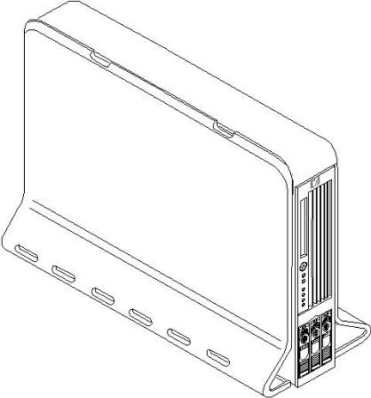
Figure 1-4 HP 9000 rp3410 and rp3440 Servers - Pedestal Mount
Detailed Server Description
This section provides information on the features that comprise the HP 9000 rp3410 and rp3440 servers.
Processor
The following is supported on the HP 9000 rp3410 and rp3440 servers:
•800 MHz/1.5 GB cache (HP 9000 rp3410 and rp3440 servers)
•1 GHz/1.5 GB cache (HP 9000 rp3440 server only)
•Both processors are available with 32 MB or 64 MB L2 cache
•HP 9000 rp3410 servers can be 1P/1C and 1P/2C
•HP 9000 rp3440 servers can be 1P/1C, 1P/2C, and 2P/2C
Memory
The following is supported on the HP 9000 rp3410 and rp3440 servers:
•12 memory DIMM slots.
•Minimum memory size is as follows:
—512 MB (2 x 256 MB DIMMs in a HP 9000 rp3410, model A7136A server).
—1 GB (4 x 256 MB DIMMs in a HP9000 rp3410 model A7136B server, or in a HP 9000 rp3440 server).
•Maximum memory size is as follows:
20 Overview
—6GB(HP9000rp3410server),24GB(HP9000rp3440serverwith2GBDIMMsinstalled in all 12 slots), or
—32 GB (HP 9000 rp3440 server with 4 GB DIMMs installed in the first eight slots)
•For the HP 9000 rp3410 server, DIMMs are as follows:
—256 MB, 512 MB, and 1 GB
—standard 184 pins 2.5V
—DDR266, CL2, registered, ECC
•For the HP 9000 rp3440 server, DIMMs are as follows:
—256 MB, 512 MB, and 1 GB, 2 GB, 4 GB
—standard 184 pins 2.5V
—DDR266, CL2, registered, ECC
•Onlyonesupportedconfigurationfor4GBDIMMs;2quads(8DIMMs);andnootherDIMMs can be installed.
•DIMMs loaded by quads enable interleaved mode and chip spare.
•Memoryisloadedacrossbothmemorybusses(twoDIMMsoneachbus)toensuremaximum bandwidth and performance.
•133 MHz memory bus frequency, 266 MTransfers/s data, 8.5 GB/s peak data bandwidth.
•Total memory bandwidth is 8.5 GB/s, split across two 4.25 GB/s memory buses.
•Open page memory latency is 80 nanoseconds.
PCI Riser
Two(HP9000rp3410server)orfour(HP9000rp3440server)independentPCI-X133MHz64-bit 3.3V 15W slots. No 5V card and hot-pluggable support.
Internal Core I/O
The following is supported on the HP 9000 rp3410 and rp3440 servers:
•Dual-channel SCSI U160 interface, two internal 68-pin connectors, one 68-pin external connector.
•SCSI backplane configured either as two channels with 2+1 drives. A SAF-TE accessory (currently not available) is required to configure the SCSI backplane as one channel with three drives.
•Three internal SCSI drive connectors are of the 80-pin type and provide drive electrical hot-pluggable capability.
•SCSI backplane is designed to support a SCSI management piggy board accessory that provides a SCSI management SAF-TE chip and shunts the backplane's channels A and B to provide three disks on channel A and leave only the external connector on channel B.
•One internal IDE connector for a slim-line optical device (CD and DVD).
•No floppy connector.
External Core I/O
The following is supported on the HP 9000 rp3410 and rp3440 servers:
•One SCSI U160 68-pin connector.
•One 10/100/1000Base-T Ethernet LAN connectors for copper cable.
•Four USB 2.0 ports.
•Three DB-9 ports (console, UPS, and modem) through a 3-connector M cable.
Power Supply Unit
The following is supported on the HP 9000 rp3410 and rp3440 servers:
Detailed Server Description |
21 |
•650W output power.
•The power supply is split in a front end block (the actual power supply case) that converts the line voltage into high DC voltage and back end voltage regulation modules (on the motherboard) that step down the front end DC voltage to the required voltages.
•Redundant and hot-pluggable power supplies (front end block only).
System Board Manageability
The following is supported on the HP 9000 rp3410 and rp3440 servers:
•Baseboard Management Controller (BMC).
•Temperature monitoring and fans regulation by BMC.
•BMC manageability console shared with system console/general purpose serial port.
•IPMI protocol for communication between BMC/system/iLO MP.
•Hardware diagnostics by BMC displayed on the front status panel.
•Locator front/rear LEDs.
•Field replacement units monitoring by BMC.
Enhanced Server Manageability Using the iLO MP
The following is supported on the HP 9000 rp3410 and rp3440 servers:
•LAN Telnet console
•Web GUI
•Serial port for local console
•Serial port for modem console
•Duplication of console screen content across all consoles
Hard Disk Drives
Three half-height hard disk drives (1-inch height).
Internal RAID
The following is supported on the HP 9000 rp3410 and rp3440 servers:
•The A9890A and A9891A RAID cards are supported to provide RAID for the embedded drives.
•The A9827A cabling kit is required for internal RAID. See the HP 9000 rp3410 and HP 9000 rp3440 Upgrade Guide for complete RAID installation instructions.
Firmware
Firmwareconsistsofmanyindividuallylinkedbinaryimagesthatareboundtogetherbyasingle framework at run time. Internally, the firmware employs a software database called a device tree to represent the structure of the hardware platform and to provide a means of associating software elements with hardware functionality.
ThefirmwareincorporatestheBootConsoleHandler(BCH)whichprovidesaninterfacebetween the operating system and the platform firmware.
The firmware supports the HP-UX 11i version 1 (and higher HP-UX versions that support PA-RISC systems) operating system through the HP 9000 processor family standards and extensions, and has no operating system-specific functionality included. The operating system is presented with the same interface to the system firmware, and all the features are available to the operating system.
22 Overview

Event IDs for Errors and Events
TheserverfirmwaregenerateseventIDssimilartochassiscodesforerrors,events,andforward progresstotheIntegratedLight-OutManagementProcessor(iLOMP)throughcommonshared memory.TheiLOMPinterpretsandstoreseventIDs.Reviewingtheseeventshelpsyoudiagnose and troubleshoot problems with the server.
Dimensions and Values
Table 1-1 lists the dimensions and values of the HP 9000 rp3410 and rp3440 servers.
Table 1-1 Server Dimensions and Values
Dimensions |
Values |
Rack dimensions (depth x width x height) |
26.8 in (67.9 cm) max. x 19.0 in (48.3 cm) x 3.4 in (8.6 cm) |
Pedestal dimensions (depth x width x height) |
26.6 in (67.5 cm) x 11.6 in (29.5 cm) x 19.5 in (49.4 cm) |
Rack weight |
Minimum: 38.6 lb (17.5 kg) |
Pedestal weight |
Maximum: 49.0 lb (22.2 kg) |
|
Minimum: 49.4 lb (22.4 kg) |
|
Maximum: 56.3 lb (25.5 kg) |
Pedestal footprint |
0.2 m2 (2.1 sq. ft.) |
Rack units |
2U |
System Board
This section provides a block diagram of the system board and descriptions of key components (integrated circuits) on the system board.
Figure 1-5 shows the system board block diagram.
Detailed Server Description |
23 |
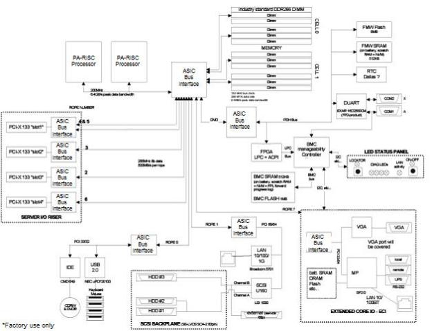
Figure 1-5 System Board Block Diagram
System Board Components
The following describes the main components of the system board:
•Dual PA-RISC processors:
—One or two processors enabled in the HP 9000 rp3410 server
—One, two, or four processors enabled in the HP 9000 rp3440 server
•ZX1 I/O and memory controller
•ZX1 PCI bus controller
•Processor dependent hardware controller
•Field processor gate array controller
•BMC
•SCSI controller
•IDE controller
•USB controller
•10/100/1000 LAN
PA RISC Processor
ThesystemboardconsistsoftwoZeroInsertionForce(ZIF)processorsockets,theCoreElectronic Complex (CEC), and circuits for clock and power generation and distribution, boundary scan, In-target Probe (ITP), and debug.
TheFrontSideBus(FSB)istheIA64processorbusbasedonbusprotocolfromIntel.Thisenables processor customer self-repair (CSR) parts to be dropped in, provided that electrical and
24 Overview
mechanicalcompatibilityandsupportcircuitryexist.AprocessorCSRconsistsofadualprocessor module with heatsink assembly.
One end of the FSB is terminated with an I/O ASIC. The other end of the bus is terminated with a CSR. An additional CSR can be loaded in the middle. For the system to function properly, the processor farthest away from the I/O ASIC must be loaded at all times to electrically terminate the FSB.
Each processor module plugs directly into and is powered by its own 12V to 1.2V power-pod. Other power for the system board comes from multiple on-board DC/DC converters. Each processormoduleisattachedtotheboardthroughaZIFsocketandtheentireCSRsecureddown by a heatsink bolster plate.
Processor Bus
The processor bus (Front Side Bus [FSB]) in this product runs at 200 MHz. Data on the FSB are transferred at a double data rate, which enables a peak FSB bandwidth of 6.4 Gb/sec.
ZX1 I/O and Memory Controller
HP 9000 rp3410 and rp3440 servers support the following features of the ZX1 I/O and memory controller chip:
•3.3 GB/s peak IO bandwidth
•Provides eight communication paths
•Peak memory bandwidth of 8.5 GBs
•Two memory cells, 144 data bits each
Memory
The memory subsystem provides two memory cells, each of which is 144 data bits wide. Each cell has six DIMM slots, which means a total of 12 DIMM slots are available. The memory bus clock speed is 133 MHz, and the data transfer rate is 266M transfers/second as data is clocked on both edges of the clock. The peak data bandwidth for this memory subsystem design is 8.5 GB/s. DIMMs must be loaded in quads with qualified modules, with the exception of 256 MB DIMMs which is loaded in pairs. Memory is protected by data error correction code (ECC), and the hardware implementation supports the chip-spare feature.
The minimum amount of memory that you can install is 512 MB (2x256 MB modules in a HP 9000 rp3410 model A7136A server), and 1 GB (4x256 MB modules in other HP 9000 rp34x0 servers). The maximum amount of memory that you can install is limited to 24 GB (12 x 2 GB modules) or 32 GB (8 x 4 GB modules) in a HP 9000 rp3440 server.
This design does not support any non industry-standard DDR DIMMs. Only qualified DIMMs are supported.
Figure 1-6 shows the memory block diagram.
Detailed Server Description |
25 |
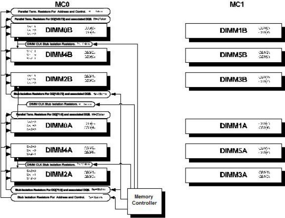
Figure 1-6 Memory Block Diagram
Memory Architecture
The I/O ASIC memory interface supports two DDR cells, each of which is 144 data bits wide. Thememorysubsystemphysicaldesignusesacomb-filterterminationschemeforboththedata and address/control buses. This part of the topology is similar to other DDR designs in the computerindustry. ClocksaredistributeddirectlyfromtheI/OASIC;eachclockpairdrivestwo DIMMs.
Memory data is protected by ECC. Eight ECC bits per DIMM protect 64 bits of data. The use of ECC enables correction of single-bit errors, and detection of multi-bit errors. Only DIMMs with ECC are qualified or supported.
DIMMs
ThememorysubsystemonlysupportsDoubleDataRateSynchronousDynamicRandomAccess Memory (DDR SDRAM) technology utilizing industry-standard PC-1600 type DDR SDRAM DIMMs,1.2"tall.Thisiscurrentlybeingusedbyhigh-volumeproducts.TheDIMMsusea184-pin JEDEC standard connector.
DIMMsareloadedingroupsoffour,knownasarankorquad(exceptfor256MBDIMMs,which is loaded in pairs). All four DIMMs in a rank or quad must be the same size. The following information summarizes the memory solutions.
Memory Array Capacities
Table 1-2 lists the memory array capacities for the server.
26 Overview

Table 1-2 Memory Array Capacities
Minimum and Maximum |
Single DIMM Size |
DDR SDRAM Count, Type and Technology |
Memory Size |
|
|
0.5 GB / 3 GB |
256 MB DIMM |
18 x 32 MB x 4 DDR SDRAMs (128 MB) |
2 GB / 6 GB |
512 MB DIMM |
36 x 32 MB x 4 DDR SDRAMs (128 MB) |
4 GB / 12 GB |
1024 MB DIMM |
36 x 64 MB x 4 DDR SDRAMs (256 MB) |
8 GB / 24 GB |
2048 MB DIMM |
36 x 128 MB x 4 DDR SDRAMs (512 MB) |
16 GB / 32 GB |
4096 MB DIMM |
36 x 256 MB x 4 DDR SDRAMs (1024 MB) |
Chip Spare Functionality
Chip spare enables an entire DDR SDRAM chip on a DIMM to be bypassed in the event that a multi-bit error is detected on the DDR SDRAM. In order to use the chip spare functionality on the server, only DIMMs built with ×4 DDR SDRAM parts are used, and these DIMMs must be loaded in quads.
The memory subsystem design supports the I/O ASIC chip’s spare functionality. Chip spare enablesanentireSDRAMchiponaDIMMtobebypassedorreplacedintheeventthatamulti-bit error is detected on that SDRAM. In order to use the chip spare functionality, only DIMMs built withx4SDRAMpartsareused,andtheseDIMMsmustbeloadedinquads(2DIMMspermemory cell,loadedinthesamelocationineachmemorycell).EachDIMMwithinaquadmustbeidentical to all the other DIMMs in the quad.
UsingtheDIMMloadingorderfigurefromabove,chipspareisachievediffouridenticalDIMMs are loaded in the slots labeled “1st” and “2nd.” If more DIMMs are added, they must be loaded in quads in order to maintain the chip spare functionality. If more DIMMs are added to the examplecase,fouridenticalDIMMs(identicaltoeachother,butcanbedifferentfromtheoriginal quad that was loaded) must be loaded in the slots labeled “3rd” and “4th.”
Maximum memory capability of the HP 9000 rp3440 server is 24 GB or 32 GB. If 4 GB DIMMs are used, install eight DIMMs in the first eight slots. The remaining slots (9-12) must remain empty when 4 GB DIMMs are used.
Serial Presence Detect
Each DIMM contains an I2C EEPROM whose content describes the module’s characteristics: speed,technology,revision,vendor,andsoon.Thisfeatureiscalledserialpresencedetect(SPD). Firmware typically uses this information to detect unmatched pairs of DIMMs, and configure certain memory subsystem parameters. The SPD information for DIMMs loaded in the system are also accessible to the BMC through the I2C bus.
I/O Bus Interface
The I/O bus interface has these features:
•Provides industry standard PCI 33 MHz and 66 MHz, PCI-X 66 MHz to 133 MHz, 32 or 64 data bit support.
•Uses 3.3V PCI only, and it does not support 5V PCI.
•Optimizes for DMA performance.
•Supports 3.3V or universal-keyed PCI cards. 5V-keyed PCI cards are not supported.
Processor Dependent Hardware Controller
The Processor Dependent Hardware (PDH) controller provides the following features.
Detailed Server Description |
27 |
•16-bit PDH bus with reserved address space for the following:
—Flash memory
—Nonvolatile memory
—Scratch RAM
—Real-time clock
—UARTs
—External registers
—Firmware read/writable registers
—Two general purpose 32-bit registers
—Semaphore registers
—Monarch selection registers
—Test and reset register
•Reset and INIT generation
Field Programmable Gate Array
The Field Programmable Gate array (FPGA) provides ACPI and LPC support for the PDH bus and provides these features:
•ACPI 2.0 interface
•LPC bus interface to support BMC
•Decoding logic for PDH devices
BMC
The BMC supports the industry-standard Intelligent Platform Management Interface (IPMI) specification. Thisspecificationdescribesthemanagementfeaturesthathavebeenbuiltintothe system board. These features include: diagnostics (both local and remote), console support, configuration management, hardware management and troubleshooting.
The BMC provides the following:
•Compliance with IPMI 1.0
•Tachometer inputs for fan speed monitoring
•Pulse width modulator outputs for fan speed control
•Push-button inputs for front panel buttons and switches
•One serial port, multiplexed with the system console port
•Remote access and intelligent chassis management bus (ICMB) support
•Three I2C master/slave ports (one of the ports is used for intelligent platform management bus (IPMB)
•Low Pin Count (LPC) bus provides access to three Keyboard Controller Style (KCS) and one-Block Transfer (BT) interface
•32-bit ARM7 RISC processor
•160-pin Low Profile Flat Pack (LQFP) package
•Firmware is provided for the following interfaces:
—IPMI
—IPMB
SCSI Controller
The SCSI controller is a LSI Logic 53C1030 chip. This chip is fully compliant with the SCSI Peripheral Interface-4 Specification (SPI-4). It has two independent SCSI channels supporting devices at speeds up to 320 MB/seconds each. The 53C1030 adheres to the PCI-X addendum, to thePCILocalSpecification,andishard-wiredtoPCIID1whichcorrespondstobit17ofthePCI AD bus.
28 Overview

IDE Interface
TheIDEcontroller(PCI649)supportstheATAPIzero(0)tofive(5)modes(from16to100MB/s). The usable speed on this system is limited to 16 MHz (ATA-33 mode, 33 MB/s) because the slimline CD/DVD devices do not support the ATA-66 and 100 modes.
The primary IDE channel is the only channel that is implemented. The IDE cable provides only one drive connector, of the master type, for the optical storage peripheral.
1 GB System LAN
The 1 GB System LAN port provides:
•Main system LAN
•10/100/1000 MB capable
USB Connectors
The USB connectors provide:
•High speed 480 MB/seconds capable
•Full speed 12 MB/seconds and low speed 1.5 MB/seconds
•Support for USB keyboard and mouse
•HP-UX supports HP USB keyboard and mouse
Disk and I/O Path Logging
SomefailuresresultinI/Opathlogging. Thesepathshelptoindicatethesourceoftheerrorand can be included in the error message or logged into console or event logs.
Table 1-3 describes the disk drive and DVD paths for the server.
Table 1-3 Internal Disk and DVD Paths
Slot |
Function Associated with Path |
Location |
ACPI Path |
|
Disk slot 0 |
Ultra 3 |
SCSI I/O for bottom removable disk |
Bottom disk slot |
0/1/1/0.0.0 |
Disk slot 1 |
Ultra 3 |
SCSI I/O for middle removable disk |
Middle disk slot |
0/1/1/0.1.0 |
Disk slot 2 |
Ultra 3 |
SCSI I/O for top removable disk |
Top disk slot |
0/1/1/1.2.0 |
DVD slot |
IDE I/O for DVD |
DVD slot |
0/0/2/0.0.0 |
|
Table 1-4 describes the extended core I/O paths for the server.
Table 1-4 Extended Core I/O Paths
Slot |
Function Associated with Path |
Location |
ACPI Path |
Core I/O |
USB port |
Rear panel (with |
0/0/1/0 |
|
|
mouse symbol) |
|
Core I/O |
USB port |
0/0/1/0 |
Rearpanel(top/white |
|
|
|
connector) |
Core I/O |
USB port |
Rear panel (with |
0/0/1/1 |
|
|
keyboard symbol) |
|
Core I/O |
USB port |
Rear panel |
0/0/1/1 |
|
|
(bottom/white |
|
|
|
connector) |
|
Core I/O |
USB port |
Internal |
0/0/1/2 |
Core I/O |
IDE controller |
System board |
0/0/2/0 |
Detailed Server Description |
29 |
 Table 1-4 Extended Core I/O Paths (continued)
Slot |
Function Associated with Path |
Core I/O |
LAN 100 port |
Core I/O |
Ultra 3 SCSI Channel A |
Core I/O |
Ultra 3 SCSI Channel B |
Core I/O |
Ultra 3 SCSI I/O— external SCSI |
Core I/O |
LAN 1000 port |
Console port |
Interface with external console (ECI) |
Remote port |
Interface with UPS (ECI) |
UPS port |
Interface with UPS |
ECI (VGA |
Not used (disabled) |
port) |
|
N/A |
Baseboard console port (CLI) |
N/A |
Baseboard serial port |
Location |
ACPI Path |
Rear panel (with LAN |
0/0/3/0 |
10/100 label) |
|
System board |
0/1/1/0 |
System board |
0/1/1/1 |
Rear panel (with SCSI |
0/1/1/1.x.y |
LVD/SE label) |
|
Rear panel (with LAN |
0/1/2/0 |
GV label) |
|
Rear panel (accessible |
0/7/1/1 |
thru W cable) |
|
Rear panel (accessible |
0/7/1/0 |
thru W cable) |
|
Rear panel (accessible |
N/A |
thru W cable) |
|
Rear panel (with VGA |
0/7/2/0 |
label) |
|
Rearpanel(withSerial |
Factory use only |
A label) |
|
Rearpanel(withSerial |
Factory use only |
B label) |
|
Table 1-5 describes the PCI I/O paths for the server.
Table 1-5 PCI I/O Paths
Slot |
Function Associated with Path |
Location |
ACPI Path |
|
Slot 1 |
64-bit, 133 |
MHz PCI-X card |
Top connector/slot in |
0/4/1/0 |
|
|
|
PCI card cage |
|
Slot 2 |
64-bit, 133 |
MHz PCI-X card |
Second connector/slot |
0/3/1/0 |
|
|
|
in PCI card cage |
|
Slot 3 |
64-bit, 133 |
MHz PCI-X card (active rp3440 only) |
Thirdconnector/slotin |
0/2/1/0 |
|
|
|
PCI card cage |
|
Slot 4 |
64-bit, 133 |
MHz PCI-X card (active rp3440 only) |
Bottom connector of |
0/6/1/0 |
|
|
|
PCI card cage |
|
Table 1-6 PCI I/O Hardware Paths
PCI Card Functionality |
MAPPER Path |
HP-UX Path |
USB Port |
0/0/1/0 |
0/0/1/0 |
USB Port |
0/0/1/0 |
0/0/1/0 |
USB Port |
0/0/1/1 |
0/0/1/1 |
USB Port |
0/0/1/1 |
0/0/1/1 |
IDE Controller |
0/0/2/0 |
0/0/2/0 |
DVD Drive |
0/0/2/0.0.0 |
0/0/2/0.0.0 |
Internal SCSI - Slot 0 |
0/1/1/0.0.0 |
0/1/1/0.0.0 |
Internal SCSI - Slot 1 |
0/1/1/0.1.0 |
0/1/1/0.1.0 |
30 Overview
Loading...