


Designjet T790
Table of contents
 Loading...
DESIGNJET T790/T1300/Z5400ps
ePrinter series & T2300 eMFP series
Service manual

For HP Internal Use Only
©Copyright Hewlett-Packard Company
2011
This document contains proprietary
information that is protected by copyright.
All rights are reserved. No part of this
document may be photocopied, reproduced,
or translated to another language without
the prior written consent of Hewlett-Packard
Company.
Edition, December 2013.

Notices
Warranty
The information contained in this
document is subject to change without
notice.
Hewlett-Packard makes no
warranty of any kind with
regard to this material,
including, but not limited to,
the implied warranties of
merchantability and fitness for
a particular purpose.
Hewlett-Packard shall not be liable for
errors contained herein or for
incidental or consequential damages
in connection with the furnishing,
performance, or use of this material.
WARNING
The procedures described in this manual are
to be performed by HP-qualified service
personnel only.
Electrical Shock Hazard
Serious shock hazard leading to death or
injury may result if you do not take the
following precautions:
●
Ensure that the ac power outlet (mains)
has a protective earth (ground)
terminal.
●
Disconnect the product from the power
source prior to performing any
maintenance.
●
Prevent water or any other liquids from
running onto electrical components or
circuits, or through openings in the
enclosure.
Electrostatic Discharge
Refer to the beginning of Chapter 4
Introduction on page 272 of this manual,
for precautions you should take to prevent
damage to the product circuits from
electrostatic discharge.
Safety Symbols
General definitions of safety symbols are
given immediately after the table of
contents.
WARNING
The Warning symbol calls attention to
a procedure, practice, or the like,
which, if not correctly performed or
adhered to, could result in personal
injury. Do not proceed beyond a
Warning symbol until the indicated
conditions are fully understood and
met.
CAUTION
The Caution symbol calls attention to
an operating procedure, practice, or
the like, which, if not correctly
performed or adhered to, could result
in damage to or destruction of part or
all of the product. Do not proceed
beyond a Caution symbol until the
indicated conditions are fully
understood and met.
Content Management Department,
Barcelona Division,
Hewlett-Packard Espanola, S.A.
Avda. Graells, 501
08190 Sant Cugat del Valles
Spain
ENWW iii

iv Notices ENWW

Using this Manual
This Service Manual contains information necessary to test, calibrate, maintain and service the
following:
RTL PostScript
HP Designjet T790 24inch CR647A CR648A
HP Designjet T790 44inch CR649A CR650A
HP Designjet T1300 44inch CR651A CR652A
HP Designjet T2300 eMFP
44inch
CN727A CN728A
HP Designjet T790 24inch
Rev.B
- CR648B
HP Designjet T790 44inch
Rev.B
- CR650B
HP Designjet T1300 44inch
Rev.B
- CR652B
HP Designjet T2300 eMFP
44inch Rev.B
- CN728B
HP Designjet Z5400ps 44inch - E1L21A
HP Designjet Z5400ps 44inch
Rev.B
- E1L21B
When information is only applicable to a specific product, the text will indicate which product it is
applicable to. There are three main areas where this might occur, and at each occurrence an icon will
also be shown:
HP Designjet T2300 Printer
series
HP Designjet T790/T1300/Z5400ps
Printer series
Web Enabled
For information about using these products, refer to the corresponding User and Quick Reference
Guides.
Readership
The procedures described in this Service Manual are to be performed by HP Certified service personnel
only.
Part Numbers
ENWW v

Part Numbers for product service parts are located in Chapter 7 Parts and Diagrams on page 239.
vi Using this Manual ENWW

Table of contents
1 Troubleshooting ................................................................................................................ 1
Using the Touch Control Panel (MFP only) ................................................................................... 2
Using the Touch Control Panel ................................................................................................... 4
Service Key Combinations ......................................................................................................... 6
Product Troubleshooting trees (MFP) ........................................................................................... 7
Paper-handling troubleshooting ................................................................................................ 15
Ink-supplies troubleshooting ..................................................................................................... 16
Print Quality .......................................................................................................................... 37
The Service Image Quality Diagnostic Print ............................................................................... 38
Reading the Diagnostic Print Results .......................................................................................... 40
Advanced Diagnostic Prints ..................................................................................................... 45
Reading the Advanced diagnostic Print Results ........................................................................... 47
Troubleshooting Print Quality Problems ..................................................................................... 53
Connectivity troubleshooting .................................................................................................... 66
2 System Error Codes ......................................................................................................... 71
Introduction ........................................................................................................................... 71
Product logs .......................................................................................................................... 72
What to do if the Touch Control Panel is blank .......................................................................... 72
Troubleshooting system Error 08:11 using LEDs of the Formatter .................................................. 76
Continuable and Non-Continuable Error Codes ......................................................................... 77
System Error Code Brief Descriptions ........................................................................................ 77
System Error Codes—Full Descriptions ...................................................................................... 80
Appendix A: How to troubleshoot SE 79:04 ............................................................................ 109
Appendix B: Emergency firmware upgrade with USB flash drive ................................................ 121
Appendix C: Obtaining the product log and the diagnostics package ........................................ 122
Appendix D: How to check the display list memory for an HP-GL/2 job ...................................... 126
3 Diagnostics Menu ......................................................................................................... 129
Introduction ......................................................................................................................... 129
Diagnostic Tests and Utilities .................................................................................................. 131
ENWW vii

4 Service Menu ................................................................................................................ 173
Introduction ......................................................................................................................... 173
Service Utilities .................................................................................................................... 173
Service Calibrations ............................................................................................................. 214
5 Parts and Diagrams ...................................................................................................... 239
Introduction ......................................................................................................................... 240
Product Support ................................................................................................................... 241
Center Covers Front (1 of 3) .................................................................................................. 242
Center Covers Front (2 of 3) .................................................................................................. 243
Center Covers Front (3 of 3) .................................................................................................. 244
Roll Covers .......................................................................................................................... 245
Center Covers (Rear) ............................................................................................................ 246
Right Cover ......................................................................................................................... 247
Left Cover ........................................................................................................................... 248
Right Hand Assemblies ......................................................................................................... 249
Left Hand Assemblies ............................................................................................................ 250
Carriage Assembly ............................................................................................................... 252
Scan-Axis Assemblies ........................................................................................................... 253
Paper Path Assemblies (Front) ................................................................................................ 254
Paper Path Assemblies (Rear) ................................................................................................. 255
Roll Supports ....................................................................................................................... 256
Scanner Parts (1 of 3) ........................................................................................................... 258
Scanner Parts (2 of 3) ........................................................................................................... 259
Scanner Parts (3 of 3) ........................................................................................................... 260
Tools 1 ............................................................................................................................... 261
Tools 2 ............................................................................................................................... 262
Miscellaneous Parts .............................................................................................................. 263
6 Removal and Installation .............................................................................................. 269
Introduction ......................................................................................................................... 272
Customer Self Repair parts .................................................................................................... 275
Service Calibration Guide to Removal and Installation .............................................................. 277
Belt Assembly ...................................................................................................................... 279
Bin Assembly ....................................................................................................................... 280
Bi-stable Springs .................................................................................................................. 283
Bumpers, Left and Right ......................................................................................................... 289
Engine Cables Kit ................................................................................................................ 293
Interconnect Cables Kit ......................................................................................................... 306
Carriage and Cutter Assembly ............................................................................................... 316
viii ENWW

Carriage Bushing, Rear ........................................................................................................ 325
Carriage Cover and Carriage Latch ....................................................................................... 327
Carriage Rail Oiler .............................................................................................................. 332
Carriage PCA ...................................................................................................................... 334
Cleanout ............................................................................................................................. 339
Center Support .................................................................................................................... 341
Converger ........................................................................................................................... 345
Scanner Piston Gas (MFP only) .............................................................................................. 347
Scanner Bumper (MFP only) ................................................................................................... 350
Right Collar Cover (MFP only) ................................................................................................ 353
Front Cover ......................................................................................................................... 360
Front Top Cover Assembly (MFP only) ..................................................................................... 361
Front Top Cover ................................................................................................................... 363
Drop Detector ...................................................................................................................... 366
Aerosol Fan Assembly .......................................................................................................... 368
EE Box ................................................................................................................................ 370
Encoder Disk and Encoder Sensor .......................................................................................... 375
Encoder Strip ....................................................................................................................... 377
Encoder Strip, spring and attachment nut ................................................................................ 378
Formatter ............................................................................................................................ 381
Freewheel Assembly ............................................................................................................. 383
Right Front Trim .................................................................................................................... 386
Full Bleed Foam ................................................................................................................... 388
Hard Disk Drive ................................................................................................................... 389
Left Ink Cartridge Door ......................................................................................................... 391
Right Ink Cartridge Door ....................................................................................................... 393
Left Ink Supply Station ........................................................................................................... 395
Ink Supply Tubes & Trailing Cable .......................................................................................... 400
Ink Supply Tubes Support Rail ................................................................................................ 409
Interconnect PCA ................................................................................................................. 411
Left Collar Cover (MFP only) .................................................................................................. 413
Left Cover ........................................................................................................................... 414
Left Front Trim ...................................................................................................................... 418
Left Scanner Cover (MFP only) ............................................................................................... 420
Scanner Latch and Hook Assembly (MFP only) ......................................................................... 422
Line Sensor .......................................................................................................................... 424
Media Advance Drive .......................................................................................................... 430
Media Lever ........................................................................................................................ 438
Media Lever Position Sensor .................................................................................................. 440
Media Output Assembly ....................................................................................................... 442
Out-of-paper Sensor ............................................................................................................. 444
ENWW ix

Left Panel ............................................................................................................................ 447
Pen to Paper Space (PPS) Solenoid ......................................................................................... 449
Pinch Arm Assembly ............................................................................................................. 451
Pinchwheel Assembly ........................................................................................................... 454
Print Zone Overdrive ............................................................................................................ 462
Power Supply Unit ................................................................................................................ 466
Real-time Clock Battery ......................................................................................................... 468
Rear Cover (MFP only) .......................................................................................................... 469
Rear Cover .......................................................................................................................... 472
Rear Deflectors .................................................................................................................... 473
Right Cover ......................................................................................................................... 475
Right Scanner Cover (MFP only) ............................................................................................. 479
Roll Cover Bumpers, Lower .................................................................................................... 482
Roll Cover, Lower ................................................................................................................. 485
Roll Cover, Upper ................................................................................................................ 489
Left Roll Guide ..................................................................................................................... 491
Right Roll Guide ................................................................................................................... 492
Roll Support, Lower Left ......................................................................................................... 493
Roll Support, Lower Right ...................................................................................................... 495
Roll Support Sensor, Lower Left .............................................................................................. 497
Roll Support Sensor, Upper Left .............................................................................................. 498
Roll Support, Upper Left ........................................................................................................ 499
Roll Support, Upper Right ...................................................................................................... 501
Scan-axis Motor ................................................................................................................... 503
Service Station ..................................................................................................................... 507
Single-sheet Sensor ............................................................................................................... 512
Spindle ............................................................................................................................... 514
Spittoon, Left ....................................................................................................................... 515
Starwheel Assembly ............................................................................................................. 517
Starwheel Lifter, Left .............................................................................................................. 519
Starwheel Lifter, Right ........................................................................................................... 521
Starwheel Motor .................................................................................................................. 525
Wall Spacers ...................................................................................................................... 527
Scanner Position Sensor (MFP only) ........................................................................................ 530
Torsion Damper (MFP only) ................................................................................................... 535
CIS Element (MFP only) ......................................................................................................... 538
Scanner Exit Media Sensors (MFP only) .................................................................................. 539
Scanner Entry Media Sensors (MFP only) ................................................................................ 540
Pressure Rollers (MFP only) .................................................................................................... 541
Scanner Controller Board (MFP only) ...................................................................................... 542
Scanner Motor Assembly (MFP only) ...................................................................................... 544
x ENWW

Taco Sensor (MFP only) ........................................................................................................ 545
Touch Control Panel ............................................................................................................. 547
Window ............................................................................................................................. 551
Window Position Sensor ....................................................................................................... 555
7 Preventive Maintenance ............................................................................................... 557
Preventive Maintenance ........................................................................................................ 557
Preventive Maintenance Kits .................................................................................................. 565
Appendix A CSR Installation Flyers .................................................................................. 569
Cutter assembly ................................................................................................................... 570
Freewheel assembly ............................................................................................................. 572
Freewheel assembly (screwdriver) .......................................................................................... 574
Left side panel (T1200) ......................................................................................................... 576
Pinch arm assembly .............................................................................................................. 578
Pinch arm assembly (screwdriver) ........................................................................................... 580
Roll cover upper bumpers ...................................................................................................... 582
Roll cover upper bumpers (screwdriver) ................................................................................... 584
Foot Extension ..................................................................................................................... 586
Front Deflector ..................................................................................................................... 587
Rear Deflector Mylar ............................................................................................................ 589
Glass Plate .......................................................................................................................... 591
Latch Handle Cover .............................................................................................................. 593
ENWW xi

xii ENWW

1 Troubleshooting
●
Using the Touch Control Panel (MFP only)
●
Using the Touch Control Panel
●
Service Key Combinations
●
Product Troubleshooting trees (MFP)
●
Paper-handling troubleshooting
●
Ink-supplies troubleshooting
●
Print Quality
●
The Service Image Quality Diagnostic Print
●
Reading the Diagnostic Print Results
●
Advanced Diagnostic Prints
●
Reading the Advanced diagnostic Print Results
●
Troubleshooting Print Quality Problems
●
Connectivity troubleshooting
ENWW 1
Using the Touch Control Panel (MFP only)
The external frame of the Touch Control Panel contains the following elements:
●
The Home LED (top-left)
is used to return to the Home Screen. When clicked only once, this
same Home Screen is displayed. When pressed for more than 4 seconds, the Accessibility Home
Screen is displayed.
●
The Cancel LED (bottom right)
is used to cancel any action, when it is active.
●
The Back LED (bottom left)
is to go back to the previous screen, when it is active.
●
The Arrow LEDs (in the middle of each side)
enables the user to navigate in both
directions.
●
The Eject LED (top-right)
enables the user to stop the USB connection.
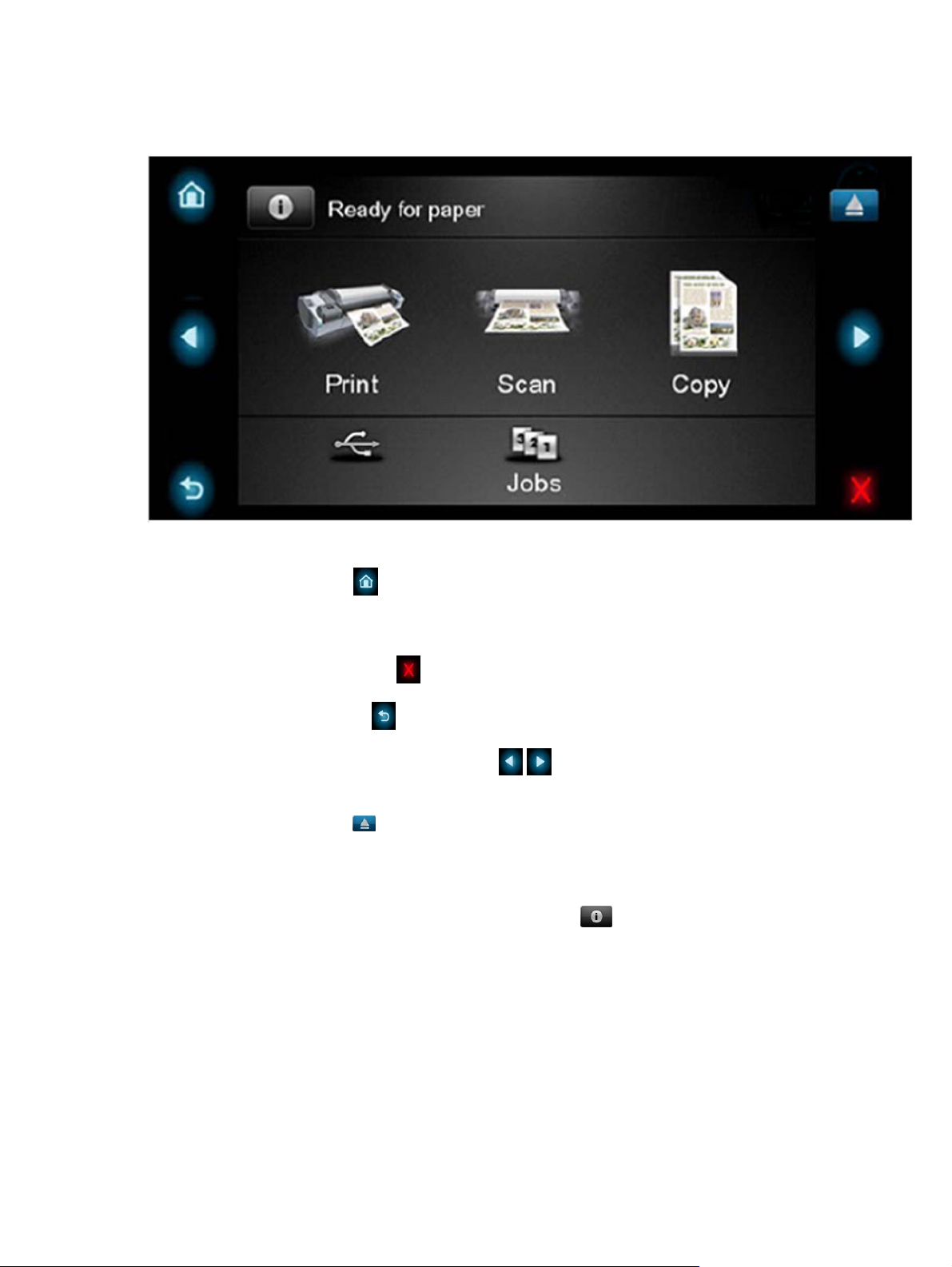
The internal part of the Touch Control Panel is the Home Screen and this is divided into three main
areas:
●
The upper area is for the Product Information (left icon)
and for displaying high priority
alerts (in text) you can press the most critical alert in the home screen and the others (less critical)
will be shown.
The main menu of the product is accessed by clicking on the Product Information icon and then
selecting the last tab (at the right side)
●
The middle area is used to place the three icons for the main work flows of the product, which
are: Print, Scan and Copy.
●
The lower area of the Home Screen is reserved for the contents area. The contents area will
contain all the functionality related with printing content, for example in the Job Queue.
2 Chapter 1 Troubleshooting ENWW

When a USB drive is inserted, a USB icon will also be displayed to the left of this area, and
when a Postscript/PDF job is being printed an Adobe logo
will display in the
bottom right area
ENWW
Using the Touch Control Panel (MFP only)
3

Using the Touch Control Panel
The Touch Control Panel is located on the front right of the printer. It gives you complete control of your
printer: from here you can print, view information about the printer, change printer settings, perform
calibrations and tests, and so on. The Touch Control Panel also displays alerts (warning and error
messages) when needed.
1. A Hi-Speed USB host port, intended for connecting a USB flash drive, which can provide files to
be printed. When a USB flash drive is inserted, a USB icon
is displayed on the Touch Control
Panel's home screen.
2. The Touch Control Panel itself: a touch-sensitive screen with a graphical user interface.
3. The Power key, with which you can turn the printer on or off. The key is illuminated when the
printer is on. It flashes when the printer is in transition between on and off.
The Touch Control Panel has a large central area to display dynamic information and icons. On the left
and right sides you can see up to six fixed icons at different times. Normally they are not all displayed
at the same time.
Left and right fixed icons
●
Press
to return to the home screen.
●
Press
to view help about the current screen.
●
Press
to go to the previous item.
4 Chapter 1 Troubleshooting ENWW

●
Press
to go to the next item.
●
Press
to go back to the previous screen. This does not discard any changes made in the
current screen.
●
Press
to cancel the current process.
Home screen dynamic icons
The following items are displayed only on the home screen.
●
Press
to view information about printer status, change printer settings, or initiate actions such
as loading paper or replacing ink supplies. A smaller warning icon appears if there are actions
that need to be performed.
●
To the right of the above button is a message showing the printer status or the most important
current alert. Press this message to see a list of all current alerts, with an icon indicating the
severity of each alert.
●
Press
to print a file from a USB flash drive, or to print from a computer.
●
Press
to view information about the USB flash drive(s). This icon appears only when one or
more USB flash drives are inserted.
●
Press
to view and manage the job queue. A smaller warning icon appears if there are jobs
on hold.
●
While a PostScript or PDF job is printing (PostScript printers only), the Adobe PDF icon
is
displayed; pressing it has no effect.
If the printer is left idle for some time, it goes into sleep mode and switches off the front-panel display.
To change the time that elapses before sleep mode, press
, then , then Setup > Front
panel options > Sleep mode wait time. You can set a time between 1 and 240 minutes.
The printer wakes from sleep mode and switches on the front-panel display whenever there is some
external interaction with it.
Information about specific uses of the Touch Control Panel can be found throughout this guide.
ENWW
Using the Touch Control Panel
5

Service Key Combinations
Table 1-1 Service Key Combinations
Label Description
Diagnostic mode 1. With the product turned off, press the Power Key
2. When the magic frame LEDs become active, select by
touching one of the following sequences:
●
CANCEL + HOME + EJECT: hp-service-1: For The
Onsite Engineer
●
CANCEL + BACK + EJECT: hp-service-2: For call
center remote support
The LEDs in the frame will blink a response to confirm the
selected sequence.
Service menu (Service Engineers only) With the product is powered on, access main menu – service
menu.
Password is 3174
For tools that require another password, this is 5494
Service menu (for users) With the product powered on, access main menu – service
menu.
Password is 3174. There is an icon in front of the option,
indicating that the tool is protected (which requires a service
password).
6 Chapter 1 Troubleshooting ENWW

Product Troubleshooting trees (MFP)
Us the following troubleshooting trees to troubleshoot issues with the MFP in the first instance.
ENWW
Product Troubleshooting trees (MFP)
7

Product Troubleshooting Tree
Figure 1-1 Troubleshooting
8 Chapter 1 Troubleshooting ENWW
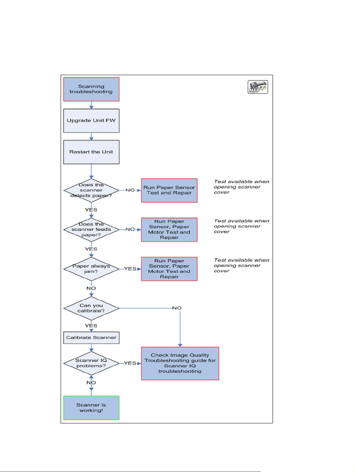
Scanner Troubleshooting Tree
Use this tree to troubleshoot the scanner in the MFP.
Figure 1-2 Scanner Troubleshooting
ENWW
Product Troubleshooting trees (MFP)
9

Scanner CIS Troubleshooting
Use this tree to troubleshoot the CIS of the scanner in the MFP.
Figure 1-3 Scanner Troubleshooting
Troubleshooting system error codes
System Error Codes on page 71 contains a list of system error codes and their respective descriptions
and recommended corrective actions. Try only one recommended action at a time and check whether
the error code has disappeared.
If you have an error code which is not documented in this Service Manual or you have an error which
you cannot resolve, then report the error to the HP Response Center or the nearest HP Support Office.
When reporting the error, have the information ready, refer to
Reporting a system error to HP support
on page 71:
10 Chapter 1 Troubleshooting ENWW

Performing a service test on a failed assembly
If possible, always perform a Service Test on the component/assembly that you are about to replace,
just to make sure that is the component/assembly that has failed.
Shown below is a list of the Service tests and the component(s) tested:
●
Scan Axis Test
◦
Star Wheel Lifter
◦
PRS
◦
Scan Axis Servosystem
◦
Cutter
●
Paper Drive Test
◦
Components of the Paper Axis Subsystem
●
Electronics Module Test
◦
Formatter
●
Carriage assembly test
◦
Carriage Assembly
●
Sensors Test
◦
Scanner Position Sensor (MFP only)
◦
Media Lever Position sensor
◦
Media sensor
◦
Upper or lower roll cover sensor
◦
Single-sheet sensor
●
Rewinder test
◦
Right Roll Support.
●
Ink Delivery System Test
◦
Ink Supply Station
◦
Ink supplies
●
Service Station test
◦
Service Station.
◦
Primer Motor
ENWW
Product Troubleshooting trees (MFP)
11

NOTE: If the test on that component/assembly passes, you should not replace it.
For information on the Service Tests and how to use them see
Diagnostics Menu on page 129.
Performing the necessary service calibrations
Is the product calibrated correctly after replacing a component? For information on the Service
Calibrations and how to use them see
Service Menu on page 173.
NOTE: Remember that certain Calibrations are required even if an Assembly has been disassembled
to gain access to another Assembly or Component.
Solving scan/print-quality problems
Refer to the Image Quality Troubleshooting Guide (in the EWS-Support Tab or in the CD).
The Touch Control Panel is blank
See What to do if the Touch Control Panel is blank on page 72.
The product does not power on
See What to do if the Touch Control Panel is blank on page 72.
The product continuously rejects printheads
▲
Clean the flex contacts on the Printhead and in the Carriage Assembly using the Carriage
Interconnect Wiper and try again.
Cover sensors are not working
1. Perform the Sensors Test. See Sensors Test on page 149.
2. Check that the cable for the faulty sensor is not damaged and is connected correctly.
3. Replace the faulty Sensor.
The line sensor has problems detecting paper
1. Check the type of paper that is being used since the Line sensor may have problems detecting
transparent paper or some types of Non-HP paper. Try loading white HP paper in to the product
and check that the Line sensor detects it.
2. The Line Sensor is not calibrated correctly. Perform the Line Sensor Calibration. See
Line Sensor
Calibration on page 228.
3. The Line Sensor is damaged or faulty. Replace the Line Sensor. See
Line Sensor on page 424.
12 Chapter 1 Troubleshooting ENWW
Troubleshooting Printer paper jams and printhead crashes
The failure modes "paper jam" and "head crash" are grouped together because in many cases a
paper jam causes the paper to lift up into the Carriage path and cause a Printhead crash, thus causing
many paper jam failures to be reported as head crashes.
1. Did the paper jam occur when loading paper?
●
If the client has had paper jams, it is common for pieces of paper to get stuck in the paper
path. Clear the paper path.
NOTE: When clearing a paper jam, sometimes paper is stuck in the paper path. To clear this,
you must lift the Media Lever and insert thicker paper into the paper path to push out the paper
that is still stuck there.
2. Is the customer using non-HP paper?
●
The use of non-HP paper can easily be the cause of paper jams and head crashes (especially
head crashes because HP paper is specially formulated to avoid cockle, one of the primary
causes of head crashes). If the paper is not HP approved, advise the customer to use HP
paper and check to see whether the problem is now solved.
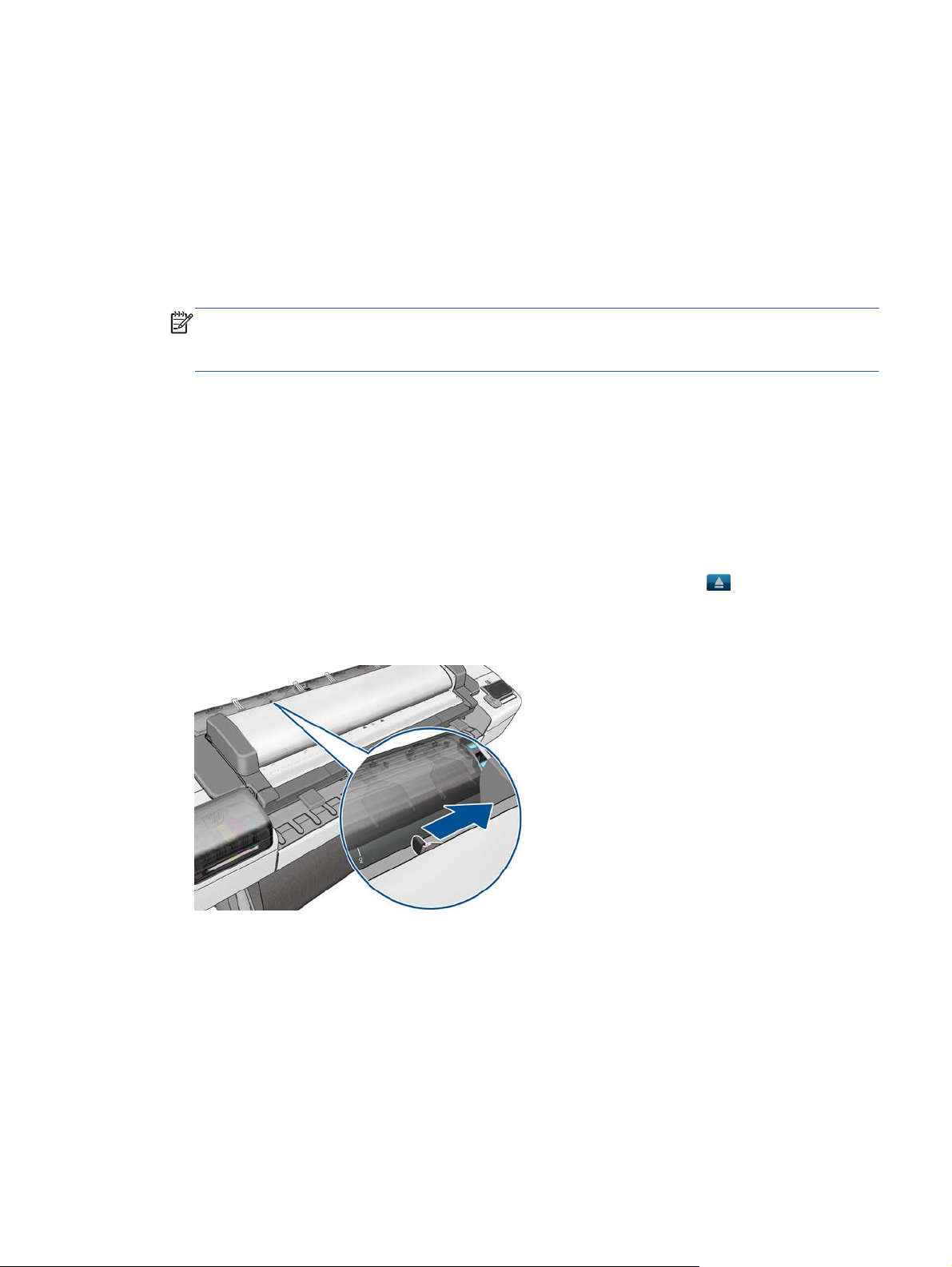
Troubleshooting Scanner paper jams (MFP only)
1. If while feeding paper into the Scanner a jam occurs, use the eject button on the Touch
Control Panel to clear the jam.
2. Unlatch the CIS Cover.
ENWW
Product Troubleshooting trees (MFP)
13

3. Open the CIS and clear the area of any paper.
The basket was damaged during the product setup
1. There are three plastic parts that could break during product installation and need replacing.
2. Check the parts table and graphics in Parts and Diagrams to identify what service parts you must
order. See
Product Support on page 241.
3. Replace the component. See
Bin Assembly on page 280.
14 Chapter 1 Troubleshooting ENWW

Paper-handling troubleshooting
Roll paper The Touch Control Panel of the product indicates that paper is misaligned or incorrectly positioned
●
The roll may be loaded the wrong way. The paper should load over the roll toward you.
●
Check that the paper is correctly loaded onto the spindle.
●
The paper may be loaded at an angle. The right-hand edge must be aligned with the blue line on the
Print Platen.
●
Check that the Right Roll Support is properly attached and screwed to the product.
●
The Rewinder, located on the Right Roll Support, should maintain proper back tension. If the Right Roll
Support is misaligned or not properly attached to the product, the Rewinder will not function properly.
●
To further diagnose problems with the Rewinder, see
Rewinder Test on page 151.
●
If the customer is experiencing problems with paper jams, check that the Overdrive is not obstructed by
paper or that the Turn Drive Roller Service Utility is being used. See
Turn Drive Roller on page 177
●
While attempting to load roll media, if the Touch Control Panel prompts you to remove paper, although
no paper is loaded, calibrate the sheet sensor, refer to
Calibrate Sheet Sensor on page 232
Sheet paper
●
The sheet must be loaded with the right-hand edge against the white line on the upper roll cover.
●
The paper may be crumpled or warped or may have irregular edges.
●
If the printer incorrectly detects the presence of a sheet of paper, perform the Calibrate Sheet Sensor,
refer to
Calibrate Sheet Sensor on page 232.
●
If hand-cut paper is used, the edges may not form a right-angle or they may be rough. If possible,
hand-cut paper should not be used. Only purchased sheet paper should be used in the product.
●
If you have problems with paper jams, check that the Overdrive is not obstructed by bits of paper or
using the Turn Drive Roller Service Utility. See
Turn Drive Roller on page 177.
●
When attempting to load sheet paper from Front Panel, if the printer displays a media skew message
repeatedly, and sheet cannot be loaded, calibrate sheet sensor. refer to
Calibrate Sheet Sensor
on page 232
ENWW
Paper-handling troubleshooting
15

Ink-supplies troubleshooting
●
Introduction to ink supplies
●
Ink cartridge levels, information and replacement
●
Printhead information, replacement and alignment
●
Ink cartridge and printhead status messages
●
Solving ink-supply problems
●
Maintaining and cleaning the printheads
Introduction to ink supplies
Introduction to ink supplies
What are ink supplies?
For each of the ink colors used in the product, there are two components, the Printhead and Ink
Cartridge. These components are called Ink Supplies.
Ink cartridges
The product's six Ink Cartridges provide matte black, magenta, yeloow, cyan, gray and photo black ink
to the Printheads. The color Ink Cartridges supplied with the product have a capacity of 69ml but
optional 130 ml are also available.
All these Ink cartridges are physically the same size. Only the internal capacity varies.
16 Chapter 1 Troubleshooting ENWW

The Ink Cartridges for the T product series require no maintenance or cleaning. As long as each Ink
Cartridge is inserted correctly into its slot, the ink will flow to the Printheads. Because the Printheads
control the amount of ink transferred to the page, you will continue to see high-quality printing results
even when the ink levels are getting low.
The Touch Control Panel displays the status of the Ink Cartridge. Using the Touch Control Panel,
detailed information can be checked on the Ink Cartridges.
Table 1-2 Available Ink Cartridges
Ink cartridge Product Model Part number
HP 72 69 ml Photo Black Ink Cartridge T series models C9397A
HP 72 69 ml Cyan Ink Cartridge T series models C9398A
HP 72 69 ml Magenta Ink Cartridge T series models C9399A
HP 72 69 ml Yellow Ink Cartridge T series models C9400A
HP 72 69 ml Gray Ink Cartridge T series models C9401A
HP 72 130 ml Matte Black Ink Cartridge T series models C9403A
HP 72 130 ml Photo Black Ink Cartridge T series models C9370A
HP 72 130 ml Cyan Ink Cartridge T series models C9371A
HP 72 130 ml Magenta Ink Cartridge T series models C9372A
HP 72 130 ml Yellow Ink Cartridge T series models C9373A
HP 72 130 ml Gray Ink Cartridge T series models C9374A
HP 726 300 ml Matte Black Ink Cartridge T1300 series only CH575A
HP 70 Matte Black 130 ml Ink Cartridge Z5400 series models C9448A
HP 70 Photo Black 130 ml Ink Cartridge Z5400 series models C9449A
HP 70 Light Gray 130 ml Ink Cartridge Z5400 series models C9451A
HP 70 Cyan 130 ml Ink Cartridge Z5400 series models C9452A
HP 70 Magenta 130 ml Ink Cartridge Z5400 series models C9453A
HP 70 Yellow 130 ml Ink Cartridge Z5400 series models C9454A
ENWW
Ink-supplies troubleshooting
17
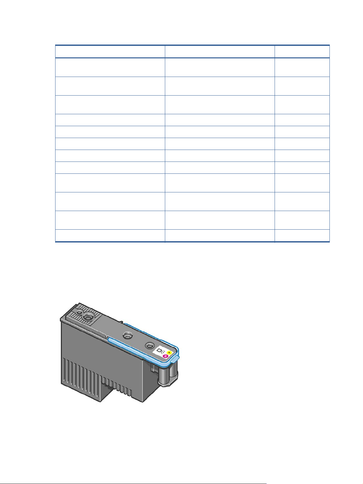
Table 1-2 Available Ink Cartridges (continued)
Ink cartridge Product Model Part number
HP 70 Matte Black 130 ml Ink Cartridge Twin
Pack
Z5400 series models CB339A
HP 70 Photo Black 130 ml Ink Cartridge Twin
Pack
Z5400 series models CB340A
HP 70 Light Gray 130 ml Ink Cartridge Twin
Pack
Z5400 series models CB342A
HP 70 Cyan 130 ml Ink Cartridge Twin Pack Z5400 series models CB343A
HP 70 Magenta 130 ml Ink Cartridge Twin Pack Z5400 series models CB344A
HP 70 Yellow 130 ml Ink Cartridge Twin Pack Z5400 series models CB345A
HP 772 300 ml Magenta Designjet Ink Cartridge Z5400 series models CN629A
HP 772 300 ml Yellow Designjet Ink Cartridge Z5400 series models CN630A
HP 772 300 ml Photo Black Designjet Ink
Cartridge
Z5400 series models CN633A
HP 772 300 ml Light Gray Designjet Ink
Cartridge
Z5400 series models CN634A
HP 772 300 ml Matte Black Designjet Ink
Cartridge
Z5400 series models CN635A
HP 772 300 ml Cyan Designjet Ink Cartridge Z5400 series models CN636A
Printheads
The Printheads are extremely durable and do not need to be replaced every time an Ink Cartridge is
replaced. They are independent of the Ink Cartridges and will continue giving excellent image-quality
results even if the Ink Cartridges are low on ink.
18 Chapter 1 Troubleshooting ENWW
Loading...