


Designjet T790
Table of contents
 Loading...
DESIGNJET T790/T1300 ePrinter series &
T2300 eMFP series
Service manual

Notices
Warranty
The information contained in this
document is subject to change without
notice.
Hewlett-Packard makes no
warranty of any kind with regard to
this material, including, but not
limited to, the implied warranties of
merchantability and fitness for a
particular purpose.
Hewlett-Packard shall not be liable for
errors contained herein or for
incidental or consequential damages
in connection with the furnishing,
performance, or use of this material.
WARNING
The procedures described in this manual are
to be performed by HP-qualified service
personnel only.
Electrical Shock Hazard
Serious shock hazard leading to death or
injury may result if you do not take the
following precautions:
●
Ensure that the ac power outlet (mains)
has a protective earth (ground)
terminal.
●
Disconnect the product from the power
source prior to performing any
maintenance.
●
Prevent water or any other liquids from
running onto electrical components or
circuits, or through openings in the
enclosure.
Electrostatic Discharge
Refer to the beginning of Chapter 4
Introduction on page 205 of this manual, for
precautions you should take to prevent
damage to the product circuits from
electrostatic discharge.
Safety Symbols
General definitions of safety symbols are
given immediately after the table of contents.
WARNING
The Warning symbol calls attention to a
procedure, practice, or the like, which,
if not correctly performed or adhered to,
could result in personal injury. Do not
proceed beyond a Warning symbol until
the indicated conditions are fully
understood and met.
CAUTION
The Caution symbol calls attention to
an operating procedure, practice, or the
like, which, if not correctly performed or
adhered to, could result in damage to or
destruction of part or all of the product.
Do not proceed beyond a Caution
symbol until the indicated conditions
are fully understood and met.
Content Management Department,
Barcelona Division,
Hewlett-Packard Espanola, S.A.
Avda. Graells, 501
08190 Sant Cugat del Valles
Spain
ENWW iii

Using this Manual
This Service Manual contains information necessary to test, calibrate, maintain and service the
following:
RTL PostScript
HP Designjet T790 24inch CR647A CR648A
HP Designjet T790 44inch CR649A CR650A
HP Designjet T1300 44inch CR651A CR652A
HP Designjet T2300 eMFP 44inch CN727A CN728A
HP Designjet T790 24inch Rev.B - CR648B
HP Designjet T790 44inch Rev.B - CR650B
HP Designjet T1300 44inch Rev.B - CR652B
HP Designjet T2300 eMFP 44inch
Rev.B
- CN728B
When information is only applicable to a specific product, the text will indicate which product it is
applicable to. There are three main areas where this might occur, and at each occurrence an icon will
also be shown:
HP Designjet T2300 Printer series HP Designjet T790/T1300 Printer series Web Enabled
For information about using these products, refer to the corresponding User and Quick Reference
Guides.
Readership
The procedures described in this Service Manual are to be performed by HP Certified service personnel
only.
Part Numbers
Part Numbers for product service parts are located in Chapter 7
Parts and Diagrams on page 177.
ENWW v

Table of contents
1 Troubleshooting
Using the Touch Control Panel (MFP only) .......................................................................................... 1
Using the Touch Control Panel ............................................................................................................ 3
Service Key Combinations ................................................................................................................... 5
Product Troubleshooting trees (MFP) .................................................................................................. 6
Paper-handling troubleshooting ......................................................................................................... 12
Ink-supplies troubleshooting ............................................................................................................... 13
Connectivity troubleshooting .............................................................................................................. 31
2 System Error Codes
Introduction ......................................................................................................................................... 35
Product logs ....................................................................................................................................... 36
What to do if the Touch Control Panel is blank .................................................................................. 36
Troubleshooting system Error 08:11 using LEDs of the Formatter .................................................... 38
Continuable and Non-Continuable Error Codes ................................................................................. 40
System Error Code Brief Descriptions ................................................................................................ 40
System Error Codes—Full Descriptions ............................................................................................. 43
Appendix A: How to troubleshoot SE 79:04 ....................................................................................... 67
Appendix B: Emergency firmware upgrade with USB flash drive ....................................................... 77
Appendix C: Obtaining the product log and the diagnostics package ................................................ 77
Appendix D: How to check the display list memory for an HP-GL/2 job ............................................. 81
3 Diagnostics Menu
Introduction ......................................................................................................................................... 83
Diagnostic Tests and Utilities ............................................................................................................. 84
4 Service Menu
Introduction ....................................................................................................................................... 121
Service Utilities ................................................................................................................................. 121
Service Calibrations ......................................................................................................................... 157
5 Parts and Diagrams
Introduction ....................................................................................................................................... 177
Product Support ............................................................................................................................... 178
Center Covers Front (1 of 3) ............................................................................................................ 179
Center Covers Front (2 of 3) ............................................................................................................ 180
ENWW vii

Center Covers Front (3 of 3) ............................................................................................................ 181
Roll Covers ....................................................................................................................................... 182
Center Covers (Rear) ....................................................................................................................... 183
Right Cover ...................................................................................................................................... 184
Left Cover ......................................................................................................................................... 185
Right Hand Assemblies .................................................................................................................... 186
Left Hand Assemblies ...................................................................................................................... 187
Carriage Assembly ........................................................................................................................... 188
Scan-Axis Assemblies ...................................................................................................................... 189
Paper Path Assemblies (Front) ........................................................................................................ 190
Paper Path Assemblies (Rear) ......................................................................................................... 191
Roll Supports .................................................................................................................................... 192
Scanner Parts (1 of 3) ...................................................................................................................... 193
Scanner Parts (2 of 3) ...................................................................................................................... 194
Scanner Parts (3 of 3) ...................................................................................................................... 195
Tools 1 .............................................................................................................................................. 196
Tools 2 .............................................................................................................................................. 197
Miscellaneous Parts ......................................................................................................................... 198
6 Removal and Installation
Introduction ....................................................................................................................................... 205
Customer Self Repair parts .............................................................................................................. 207
Service Calibration Guide to Removal and Installation .................................................................... 208
Belt Assembly ................................................................................................................................... 210
Bin Assembly .................................................................................................................................... 210
Bi-stable Springs ............................................................................................................................. 213
Bumpers, Left and Right ................................................................................................................... 218
Engine Cables Kit ............................................................................................................................. 221
Interconnect Cables Kit .................................................................................................................... 232
Carriage and Cutter Assembly ......................................................................................................... 240
Carriage Bushing, Rear .................................................................................................................... 248
Carriage Cover and Carriage Latch ................................................................................................. 250
Carriage Rail Oiler ............................................................................................................................ 254
Carriage PCA ................................................................................................................................... 255
Cleanout ........................................................................................................................................... 260
Center Support ................................................................................................................................. 261
Converger ......................................................................................................................................... 264
Scanner Piston Gas (MFP only) ....................................................................................................... 266
Scanner Bumper (MFP only) ............................................................................................................ 269
Right Collar Cover (MFP only) ......................................................................................................... 273
Front Cover ...................................................................................................................................... 278
Front Top Cover Assembly (MFP only) ............................................................................................ 279
Front Top Cover ............................................................................................................................... 281
Drop Detector ................................................................................................................................... 283
EE Box ............................................................................................................................................. 284
Encoder Disk and Encoder Sensor .................................................................................................. 289
Encoder Strip .................................................................................................................................... 290
viii ENWW

Encoder Strip, spring and attachment nut ........................................................................................ 291
Formatter .......................................................................................................................................... 293
Freewheel Assembly ........................................................................................................................ 295
Right Front Trim ............................................................................................................................... 297
Full Bleed Foam ............................................................................................................................... 298
Hard Disk Drive ................................................................................................................................ 299
Left Ink Cartridge Door ..................................................................................................................... 300
Right Ink Cartridge Door ................................................................................................................... 301
Left Ink Supply Station ..................................................................................................................... 303
Ink Supply Tubes & Trailing Cable ................................................................................................... 308
Ink Supply Tubes Support Rail ......................................................................................................... 317
Interconnect PCA ............................................................................................................................. 319
Left Collar Cover (MFP only) ............................................................................................................ 320
Left Cover ......................................................................................................................................... 321
Left Front Trim .................................................................................................................................. 324
Left Scanner Cover (MFP only) ........................................................................................................ 325
Scanner Latch and Hook Assembly (MFP only) ............................................................................... 327
Line Sensor ...................................................................................................................................... 329
Media Advance Drive ....................................................................................................................... 334
Media Lever ...................................................................................................................................... 341
Media Lever Position Sensor ........................................................................................................... 342
Media Output Assembly ................................................................................................................... 344
Out-of-paper Sensor ......................................................................................................................... 345
Left Panel ......................................................................................................................................... 348
Pen to Paper Space (PPS) Solenoid ................................................................................................ 349
Pinch Arm Assembly ....................................................................................................................... 351
Pinchwheel Assembly ...................................................................................................................... 353
Print Zone Overdrive ........................................................................................................................ 361
Power Supply Unit ............................................................................................................................ 366
Real-time Clock Battery .................................................................................................................... 367
Rear Cover (MFP only) .................................................................................................................... 367
Rear Cover ....................................................................................................................................... 370
Rear Deflectors ................................................................................................................................ 371
Right Cover ...................................................................................................................................... 372
Right Scanner Cover (MFP only) ..................................................................................................... 376
Roll Cover Bumpers, Lower ............................................................................................................. 379
Roll Cover, Lower ............................................................................................................................. 382
Roll Cover, Upper ............................................................................................................................. 385
Left Roll Guide .................................................................................................................................. 386
Right Roll Guide ............................................................................................................................... 387
Roll Support, Lower Left .................................................................................................................. 388
Roll Support, Lower Right ............................................................................................................... 389
Roll Support Sensor, Lower Left ..................................................................................................... 391
Roll Support Sensor, Upper Left ..................................................................................................... 392
Roll Support, Upper Left ................................................................................................................... 393
Roll Support, Upper Right ................................................................................................................ 395
Scan-axis Motor ............................................................................................................................... 396
ENWW ix

Service Station ................................................................................................................................. 400
Single-sheet Sensor ......................................................................................................................... 405
Spindle ............................................................................................................................................. 406
Spittoon, Left .................................................................................................................................... 407
Starwheel Assembly ......................................................................................................................... 408
Starwheel Lifter, Left ........................................................................................................................ 409
Starwheel Lifter, Right ...................................................................................................................... 411
Starwheel Motor ............................................................................................................................... 413
Wall Spacers .................................................................................................................................... 415
Scanner Position Sensor (MFP only) ............................................................................................... 417
Torsion Damper (MFP only) ............................................................................................................. 421
CIS Element (MFP only) ................................................................................................................... 424
Scanner Exit Media Sensors (MFP only) ......................................................................................... 425
Scanner Entry Media Sensors (MFP only) ....................................................................................... 426
Pressure Rollers (MFP only) ............................................................................................................ 426
Scanner Controller Board (MFP only) .............................................................................................. 427
Scanner Motor Assembly (MFP only) ............................................................................................... 429
Taco Sensor (MFP only) .................................................................................................................. 430
Touch Control Panel ......................................................................................................................... 432
Window ............................................................................................................................................. 435
Window Position Sensor .................................................................................................................. 438
7 Preventive Maintenance
Preventive Maintenance ................................................................................................................... 440
Preventive Maintenance Kits ............................................................................................................ 447
Appendix A CSR Installation Flyers
Cutter assembly ............................................................................................................................... 450
Freewheel assembly ........................................................................................................................ 451
Freewheel assembly (screwdriver) ................................................................................................... 453
Left side panel (T1200) .................................................................................................................... 455
Pinch arm assembly ......................................................................................................................... 457
Pinch arm assembly (screwdriver) ................................................................................................... 459
Roll cover upper bumpers ................................................................................................................ 461
Roll cover upper bumpers (screwdriver) .......................................................................................... 463
Foot Extension ................................................................................................................................. 465
Front Deflector .................................................................................................................................. 466
Rear Deflector Mylar ........................................................................................................................ 468
Glass Plate ....................................................................................................................................... 470
Latch Handle Cover .......................................................................................................................... 473
x ENWW
1 Troubleshooting
●
Using the Touch Control Panel (MFP only)
●
Using the Touch Control Panel
●
Service Key Combinations
●
Product Troubleshooting trees (MFP)
●
Paper-handling troubleshooting
●
Ink-supplies troubleshooting
●
Connectivity troubleshooting
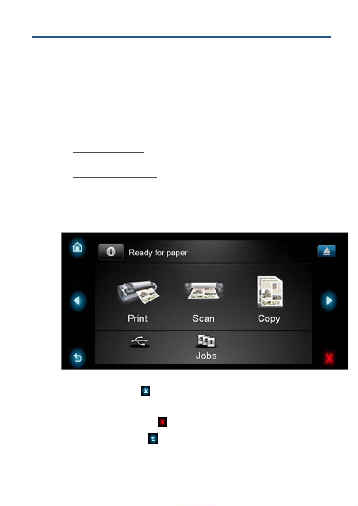
Using the Touch Control Panel (MFP only)
The external frame of the Touch Control Panel contains the following elements:
●
The Home LED (top-left)
is used to return to the Home Screen. When clicked only once, this
same Home Screen is displayed. When pressed for more than 4 seconds, the Accessibility Home
Screen is displayed.
●
The Cancel LED (bottom right)
is used to cancel any action, when it is active.
●
The Back LED (bottom left)
is to go back to the previous screen, when it is active.
ENWW Using the Touch Control Panel (MFP only) 1

●
The Arrow LEDs (in the middle of each side)
enables the user to navigate in both directions.
●
The Eject LED (top-right)
enables the user to stop the USB connection.
The internal part of the Touch Control Panel is the Home Screen and this is divided into three main
areas:
●
The upper area is for the Product Information (left icon)
and for displaying high priority alerts
(in text) you can press the most critical alert in the home screen and the others (less critical) will
be shown.
The main menu of the product is accessed by clicking on the Product Information icon and then
selecting the last tab (at the right side)
●
The middle area is used to place the three icons for the main work flows of the product, which are:
Print, Scan and Copy.
●
The lower area of the Home Screen is reserved for the contents area. The contents area will
contain all the functionality related with printing content, for example in the Job Queue.
When a USB drive is inserted, a USB icon
will also be displayed to the left of this area, and
when a Postscript/PDF job is being printed an Adobe logo
will display in the
bottom right area
2 Chapter 1 Troubleshooting ENWW
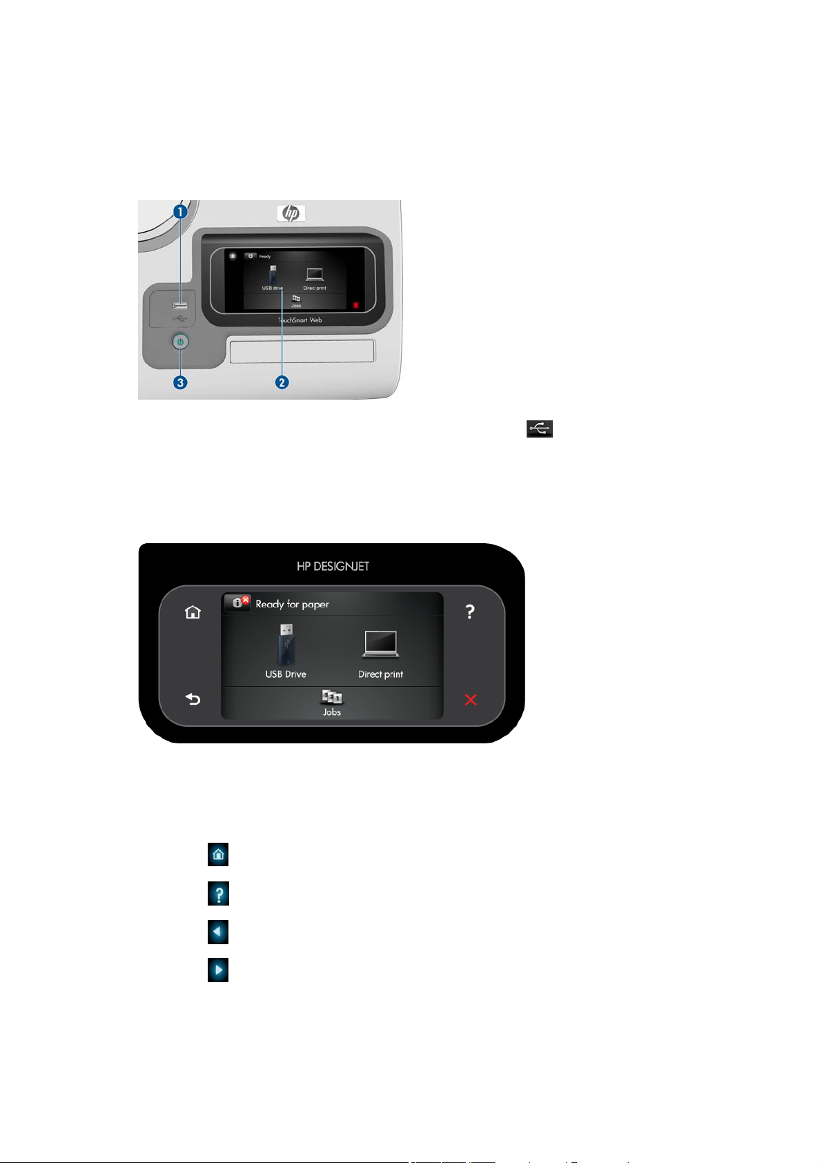
Using the Touch Control Panel
The Touch Control Panel is located on the front right of the printer. It gives you complete control of your
printer: from here you can print, view information about the printer, change printer settings, perform
calibrations and tests, and so on. The Touch Control Panel also displays alerts (warning and error
messages) when needed.
1. A Hi-Speed USB host port, intended for connecting a USB flash drive, which can provide files to
be printed. When a USB flash drive is inserted, a USB icon
is displayed on the Touch Control
Panel's home screen.
2. The Touch Control Panel itself: a touch-sensitive screen with a graphical user interface.
3. The Power key, with which you can turn the printer on or off. The key is illuminated when the printer
is on. It flashes when the printer is in transition between on and off.
The Touch Control Panel has a large central area to display dynamic information and icons. On the left
and right sides you can see up to six fixed icons at different times. Normally they are not all displayed
at the same time.
Left and right fixed icon s
●
Press
to return to the home screen.
●
Press
to view help about the current screen.
●
Press
to go to the previous item.
●
Press
to go to the next item.
ENWW Using the Touch Control Panel 3

●
Press
to go back to the previous screen. This does not discard any changes made in the current
screen.
●
Press
to cancel the current process.
Home screen dynamic icons
The following items are displayed only on the home screen.
●
Press
to view information about printer status, change printer settings, or initiate actions such
as loading paper or replacing ink supplies. A smaller warning icon appears if there are actions that
need to be performed.
●
To the right of the above button is a message showing the printer status or the most important
current alert. Press this message to see a list of all current alerts, with an icon indicating the severity
of each alert.
●
Press
to print a file from a USB flash drive, or to print from a computer.
●
Press
to view information about the USB flash drive(s). This icon appears only when one or
more USB flash drives are inserted.
●
Press
to view and manage the job queue. A smaller warning icon appears if there are jobs on
hold.
●
While a PostScript or PDF job is printing (PostScript printers only), the Adobe PDF icon
is
displayed; pressing it has no effect.
If the printer is left idle for some time, it goes into sleep mode and switches off the front-panel display.
To change the time that elapses before sleep mode, press
, then , then Setup > Front panel
options > Sleep mode wait time. You can set a time between 1 and 240 minutes.
The printer wakes from sleep mode and switches on the front-panel display whenever there is some
external interaction with it.
Information about specific uses of the Touch Control Panel can be found throughout this guide.
4 Chapter 1 Troubleshooting ENWW

Service Key Combinations
Table 1-1 Service Key Combinations
Label Description
Diagnostic mode 1. With the product turned off, press the Power Key
2. When the magic frame LEDs become active, select by
touching one of the following sequences:
◦
CANCEL + HOME + EJECT: hp-service-1: For The
Onsite Engineer
◦
CANCEL + BACK + EJECT: hp-service-2: For call
center remote support
The LEDs in the frame will blink a response to confirm the
selected sequence.
Service menu (Service Engineers only) With the product is powered on, access main menu – service
menu.
Password is 3174
For tools that require another password, this is 5494
Service menu (for users) With the product powered on, access main menu – service
menu.
Password is 3174. There is an icon in front of the option,
indicating that the tool is protected (which requires a service
password).
ENWW Service Key Combinations 5

Product Troubleshooting trees (MFP)
Us the following troubleshooting trees to troubleshoot issues with the MFP in the first instance.
Product Troubleshooting Tree
Use this tree to troubleshoot the MFP.
Figure 1-1 Troubleshooting
6 Chapter 1 Troubleshooting ENWW
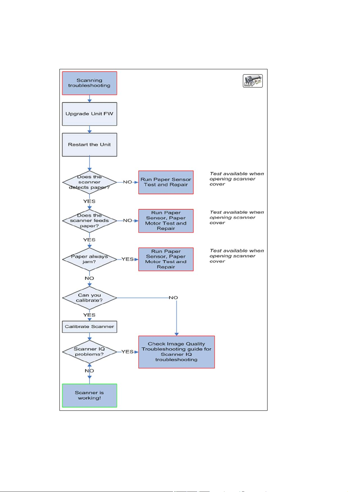
Scanner Troubleshooting Tree
Use this tree to troubleshoot the scanner in the MFP.
Figure 1-2 Scanner Troubleshooting
ENWW Product Troubleshooting trees (MFP) 7

Scanner CIS Troubleshooting
Use this tree to troubleshoot the CIS of the scanner in the MFP.
Figure 1-3 Scanner Troubleshooting
Troubleshooting system error codes
System Error Codes on page 35 contains a list of system error codes and their respective descriptions
and recommended corrective actions. Try only one recommended action at a time and check whether
the error code has disappeared.
If you have an error code which is not documented in this Service Manual or you have an error which
you cannot resolve, then report the error to the HP Response Center or the nearest HP Support Office.
When reporting the error, have the information ready, refer to
Reporting a system error to HP support
on page 35:
8 Chapter 1 Troubleshooting ENWW

Performing a service test on a failed assembly
If possible, always perform a Service Test on the component/assembly that you are about to replace,
just to make sure that is the component/assembly that has failed.
Shown below is a list of the Service tests and the component(s) tested:
●
Scan Axis Test
◦
Star Wheel Lifter
◦
PRS
◦
Scan Axis Servosystem
◦
Cutter
●
Paper Drive Test
◦
Components of the Paper Axis Subsystem
●
Electronics Module Test
◦
Formatter
●
Carriage assembly test
◦
Carriage Assembly
●
Sensors Test
◦
Scanner Position Sensor (MFP only)
◦
Media Lever Position sensor
◦
Media sensor
◦
Upper or lower roll cover sensor
◦
Single-sheet sensor
●
Rewinder test
◦
Right Roll Support.
●
Ink Delivery System Test
◦
Ink Supply Station
◦
Ink supplies
●
Service Station test
◦
Service Station.
◦
Primer Motor
NOTE: If the test on that component/assembly passes, you should not replace it.
For information on the Service Tests and how to use them see
Diagnostics Menu on page 83.
Performing the necessary service calibrations
Is the product calibrated correctly after replacing a component? For information on the Service
Calibrations and how to use them see
Service Menu on page 121.
ENWW Product Troubleshooting trees (MFP) 9

NOTE: Remember that certain Calibrations are required even if an Assembly has been disassembled
to gain access to another Assembly or Component.
Solving scan/print-quality problems
Refer to the Image Quality Troubleshooting Guide (in the EWS-Support Tab or in the CD).
The Touch Control Panel is blank
See What to do if the Touch Control Panel is blank on page 36.
The product does not power on
See What to do if the Touch Control Panel is blank on page 36.
The product continuously rejects printheads
▲
Clean the flex contacts on the Printhead and in the Carriage Assembly using the Carriage
Interconnect Wiper and try again.
Cover sensors are not working
1. Perform the Sensors Test. See Sensors Test on page 100.
2. Check that the cable for the faulty sensor is not damaged and is connected correctly.
3. Replace the faulty Sensor.
The line sensor has problems detecting paper
1. Check the type of paper that is being used since the Line sensor may have problems detecting
transparent paper or some types of Non-HP paper. Try loading white HP paper in to the product
and check that the Line sensor detects it.
2. The Line Sensor is not calibrated correctly. Perform the Line Sensor Calibration. See
Line Sensor
Calibration on page 168.
3. The Line Sensor is damaged or faulty. Replace the Line Sensor. See
Line Sensor on page 329.
Troubleshooting Printer paper jams and printhead crashes
The failure modes "paper jam" and "head crash" are grouped together because in many cases a paper
jam causes the paper to lift up into the Carriage path and cause a Printhead crash, thus causing many
paper jam failures to be reported as head crashes.
1. Did the paper jam occur when loading paper?
●
If the client has had paper jams, it is common for pieces of paper to get stuck in the paper
path. Clear the paper path.
NOTE: When clearing a paper jam, sometimes paper is stuck in the paper path. To clear this,
you must lift the Media Lever and insert thicker paper into the paper path to push out the paper
that is still stuck there.
2. Is the customer using non-HP paper?
●
The use of non-HP paper can easily be the cause of paper jams and head crashes (especially
head crashes because HP paper is specially formulated to avoid cockle, one of the primary
causes of head crashes). If the paper is not HP approved, advise the customer to use HP
paper and check to see whether the problem is now solved.
10 Chapter 1 Troubleshooting ENWW
Troubleshooting Scanner paper jams (MFP only)
1. If while feeding paper into the Scanner a jam occurs, use the eject button on the Touch Control
Panel to clear the jam.
2. Unlatch the CIS Cover.
3. Open the CIS and clear the area of any paper.
The basket was damaged during the product setup
1. There are three plastic parts that could break during product installation and need replacing.
2. Check the parts table and graphics in Parts and Diagrams to identify what service parts you must
order. See
Product Support on page 178.
3. Replace the component. See
Bin Assembly on page 210.
ENWW Product Troubleshooting trees (MFP) 11

Paper-handling troubleshooting
Roll paper The Touch Control Panel of the product indicates that paper is misaligned or incorrectly positioned
●
The roll may be loaded the wrong way. The paper should load over the roll toward you.
●
Check that the paper is correctly loaded onto the spindle.
●
The paper may be loaded at an angle. The right-hand edge must be aligned with the blue line on the
Print Platen.
●
Check that the Right Roll Support is properly attached and screwed to the product.
●
The Rewinder, located on the Right Roll Support, should maintain proper back tension. If the Right Roll
Support is misaligned or not properly attached to the product, the Rewinder will not function properly.
●
To further diagnose problems with the Rewinder, see
Rewinder Test on page 102.
●
If the customer is experiencing problems with paper jams, check that the Overdrive is not obstructed
by paper or that the Turn Drive Roller Service Utility is being used. See
Turn Drive Roller
on page 124
●
While attempting to load roll media, if the Touch Control Panel prompts you to remove paper, although
no paper is loaded, calibrate the sheet sensor, refer to
Calibrate Sheet Sensor on page 173
Sheet paper
●
The sheet must be loaded with the right-hand edge against the white line on the upper roll cover.
●
The paper may be crumpled or warped or may have irregular edges.
●
If the printer incorrectly detects the presence of a sheet of paper, perform the Calibrate Sheet Sensor,
refer to
Calibrate Sheet Sensor on page 173.
●
If hand-cut paper is used, the edges may not form a right-angle or they may be rough. If possible, hand-
cut paper should not be used. Only purchased sheet paper should be used in the product.
●
If you have problems with paper jams, check that the Overdrive is not obstructed by bits of paper or
using the Turn Drive Roller Service Utility. See
Turn Drive Roller on page 124.
●
When attempting to load sheet paper from Front Panel, if the printer displays a media skew message
repeatedly, and sheet cannot be loaded, calibrate sheet sensor. refer to
Calibrate Sheet Sensor
on page 173
12 Chapter 1 Troubleshooting ENWW
Ink-supplies troubleshooting
●
Introduction to ink supplies
●
Ink cartridge levels, information and replacement
●
Printhead information, replacement and alignment
●
Ink cartridge and printhead status messages
●
Solving ink-supply problems
●
Maintaining and cleaning the printheads
Introduction to ink supplies
Introduction to ink supplies
What are ink supplies?
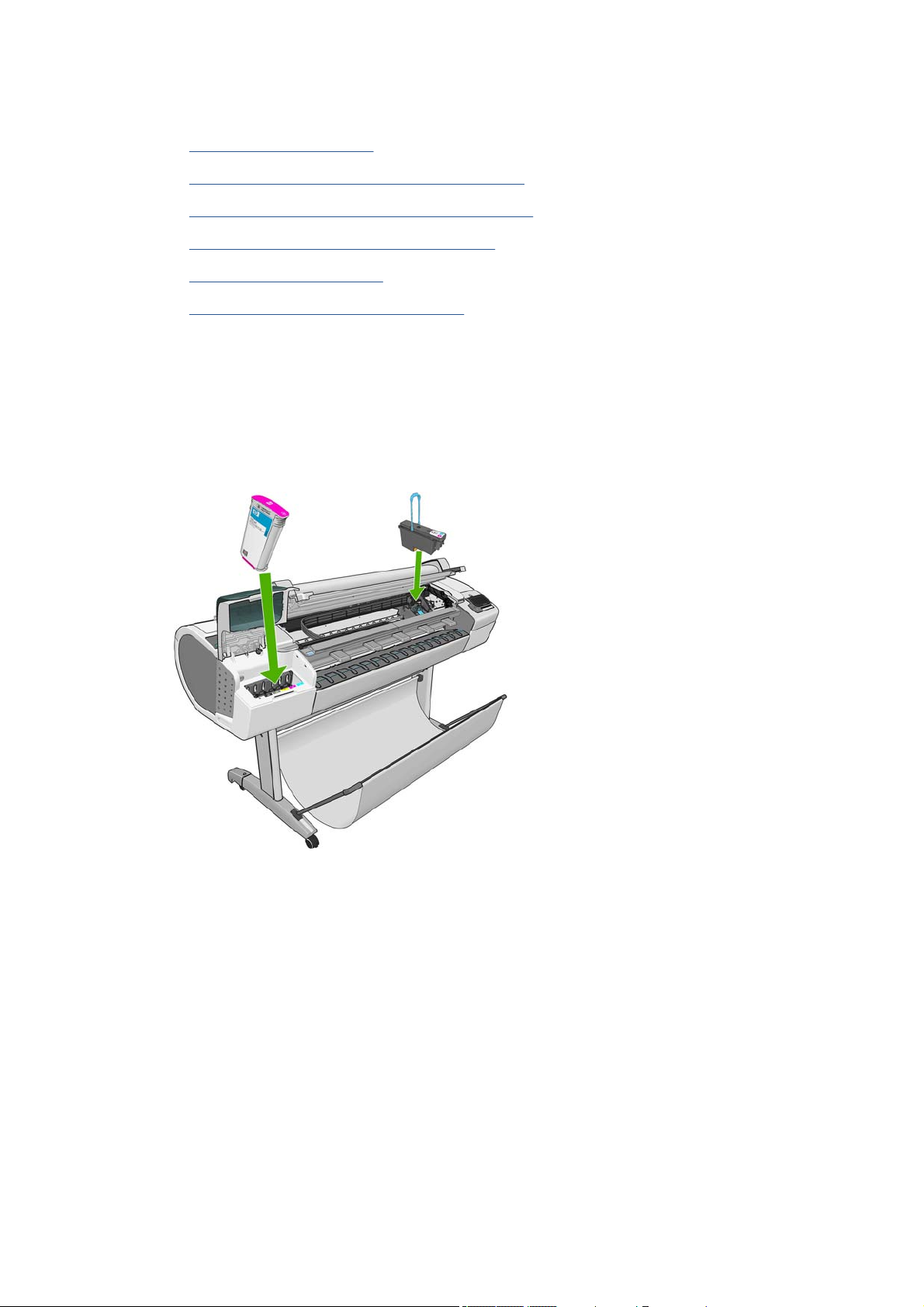
For each of the ink colors used in the product, there are two components, the Printhead and Ink
Cartridge. These components are called Ink Supplies.
Ink cartridges
The product's six Ink Cartridges provide matte black, magenta, yeloow, cyan, gray and photo black ink
to the Printheads. The color Ink Cartridges supplied with the product have a capacity of 69ml but optional
130 ml are also available.
All these Ink cartridges are physically the same size. Only the internal capacity varies.
ENWW Ink-supplies troubleshooting 13

The Ink Cartridges for the T product series require no maintenance or cleaning. As long as each Ink
Cartridge is inserted correctly into its slot, the ink will flow to the Printheads. Because the Printheads
control the amount of ink transferred to the page, you will continue to see high-quality printing results
even when the ink levels are getting low.
The Touch Control Panel displays the status of the Ink Cartridge. Using the Touch Control Panel,
detailed information can be checked on the Ink Cartridges.
Table 1-2 Available Ink Cartridges
Ink cartridge Part number
HP 72 69 ml Photo Black Ink Cartridge C9397A
HP 72 69 ml Cyan Ink Cartridge C9398A
HP 72 69 ml Magenta Ink Cartridge C9399A
HP 72 69 ml Yellow Ink Cartridge C9400A
HP 72 69 ml Gray Ink Cartridge C9401A
HP 72 130 ml Matte Black Ink Cartridge C9403A
HP 72 130 ml Photo Black Ink Cartridge C9370A
HP 72 130 ml Cyan Ink Cartridge C9371A
HP 72 130 ml Magenta Ink Cartridge C9372A
HP 72 130 ml Yellow Ink Cartridge C9373A
HP 72 130 ml Gray Ink Cartridge C9374A
HP 726 300 ml Matte Black Ink Cartridge (T1300 series only) CH575A
Printheads
The Printheads are extremely durable and do not need to be replaced every time an Ink Cartridge is
replaced. They are independent of the Ink Cartridges and will continue giving excellent image-quality
results even if the Ink Cartridges are low on ink.
14 Chapter 1 Troubleshooting ENWW

Table 1-3 Available Printheads
Product Model Part number
HP 72 Gray & Photo Black Printhead All C9380A
HP 72 Magenta & Cyan Printhead C9383A
HP 72 Matte Black & Yellow Printhead C9384A
General information about th e ink supplies
For optimum results from the product and modular ink delivery system always follow these guidelines
when handling the ink supplies:
●
Always install the Ink Cartridges and Printheads before the expiration date, which is on the
packaging.
●
Install Ink Cartridges and Printheads in their color-coded slots.
●
Follow the instructions on the Touch Control Panel of the product during installation.
●
Avoid unnecessary removal of the Ink Cartridges and Printheads.
●
When turning off the product always use the Power button on the Touch Control Panel. The
Printheads are then stored correctly which prevents them from drying out.
●
The Ink Cartridges should never be removed while the product is printing. They should only be
removed when the product is ready for you to replace them. The Touch Control Panel will guide
you through the removal and installation procedure.
General precautions when handling ink supplies
Use the following precautions when handling Ink Supplies:
NOTE: Do not touch, wipe or attempt to clean the printhead nozzles. This can damage the printhead.
●
Handle the ink supplies with care. In particular the Printhead, which is a high precision device and
must be handled carefully.
●
Do not touch the Printhead nozzles.
●
Do not put the Printhead down on the nozzles.
●
Do not be rough when handling the Printheads. Always set them down gently
ENWW Ink-supplies troubleshooting 15

●
Do not drop the Printheads.
●
Proper handling will assure optimum performance throughout the Printhead life.
●
Do not touch the end of the Ink Cartridge which is inserted into the product as there may be a small
amount of ink on the connection.
●
Avoid storing partially used Ink Cartridges on their ends.
When should you replace the ink supplies?
When to change the ink supplies is mostly determined by you with guidance from the Touch Control
Panel. In conjunction with the messages displayed in the Touch Control Panel and the message
explanations in this chapter, you will be able to choose for yourself when is the right time to change the
ink supplies.
The product will also display the ink level and will tell you when the ink supply is low on ink. This means
you have constantly updated information about the ink supplies.
Ink cartridge levels, information and replacement
Ink cartridge levels and information
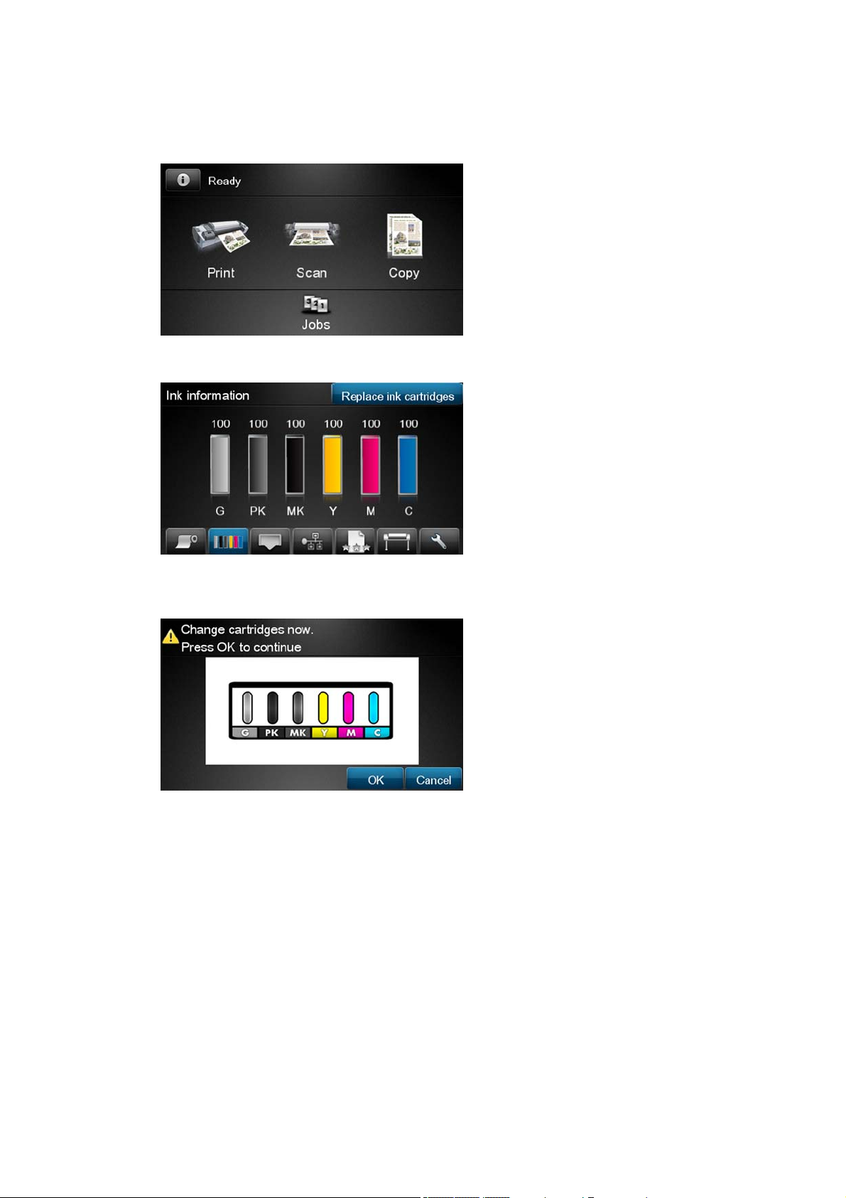
The Touch Control Panel displays Ink Levels shown as level bars. These bars represent how much ink
is remaining in the Ink Cartridges: as ink is used up the bars get shorter in length. To view the ink levels
perform the following steps:
1.
Press on the Information icon
.
2. Press on the Ink Menu icon. Each of the Ink Cartridges is displayed as a bar indicating the level of
ink remaining.
3. To get further information of an Ink Cartridge, press on the corresponding bar that you want to view.
The information supplied is:
●
The current status of the Ink Cartridge.
●
The current ink level of the ink cartridge in milliliters.
16 Chapter 1 Troubleshooting ENWW

●
Original capacity of the ink cartridge in milliliters.
●
The make of the Ink Cartridge (HP no.72 is recommended).
●
The product name of the Ink Cartridge.
●
The product number of the Ink Cartridge.
●
The serial number of the Ink Cartridge.
●
The Expiration Date of the ink cartridge.
●
The current warranty status of the Ink Cartridge.
●
The manufacturer of the Ink Cartridge (HP is recommended).
The product consumes more gray ink than M, C, or Y
This is not a problem, and no action should be taken to “correct” this attribute of the product.
In general the higher frequency of change is because Matte Black ink is the one that is used for lines
and black objects in technical papers (bond, coated, HW coated, natural tracing paper, etc.), which are
the types of contents that are more commonly printed with this type of product.
About gray ink
The T Series products are the first HP Designjet technical products to include Gray ink. One thing that
users may notice is that Gray ink is used in higher quantities than Cyan, Magenta and Yellow inks. This
happens because of the following reasons:
1. Gray areas (which are very typical in technical drawings) can now be printed by using only Gray
ink. In the past, these areas had to be printed by combining Cyan, Magenta and Yellow inks. This
means that Gray ink is used more frequently than the rest of the inks (C, M, Y) which are now used
less frequently, so the difference in consumption is noticeable. However overall the T Series
products will actually need to use in total less ink to print gray areas than previous Designjet
products.
2. Soft colors can now be printed by combining C, M and Y inks with Gray. The addition of Gray ink
softens the color, improving transition areas. It also allows printing soft colors by using less C, M
and Y. These two types of contents are very typical and make the consumption of Gray to increase
and the consumption of C, M and Y to decrease.
Conclusion
However, no matter the combination of inks that are used, when the total cc’s of ink are added up, the
T Series products will always have a lower ink consumption than the HP Designjet 500, 800 and 1000
series for equivalent contents with equivalent levels of print quality.
Changing an Ink Cartridge
There are two occasions when you need to remove an ink cartridge:
●
The ink cartridge is very low and you want to replace it with a full cartridge for unattended printing
(you can use up the remaining ink in the first cartridge at a more convenient time).
●
The ink cartridge is empty or faulty, and you must replace it to continue printing.
NOTE: Do not try to remove an ink cartridge while printing. Remove an ink cartridge only if you are
ready to insert another one.
Make sure the product wheels are locked (the brake lever is pressed down) to prevent the product from
moving.
ENWW Ink-supplies troubleshooting 17
To change an ink cartridge there are two methods, the first is shown below by using the ink tab, the
second method is to access the main menu option (refer to the User's Guide for further details).
1. Press on the Information icon.
2. Press on the Ink Menu icon and the following screen is displayed.
Press on the Replace ink cartridge tab
3. The following screen is displayed, press OK to continue.
4. Open the relevant Ink Cartridge cover for the Ink Cartridge you want to replace.
5. Pull the required Ink Cartridge straight up to remove it from the product. The Touch Control Panel
indicates the missing Ink Cartridge.
6. Before removing the cartridge from its wrapping, shake it vigorously.
7. Unwrap the new ink cartridge, find the label identifying the ink color. Check that the letter or letters
marking the empty slot, matches the letter or letters on the cartridge label.
8. Insert the ink cartridge into its slot.
9. Push the cartridge into the slot until it snaps into position. You will hear a beep and see confirmation
that the cartridge has been inserted.
10. When all cartridges have been inserted, close the cover.
18 Chapter 1 Troubleshooting ENWW
Printhead information, replacement and alignment
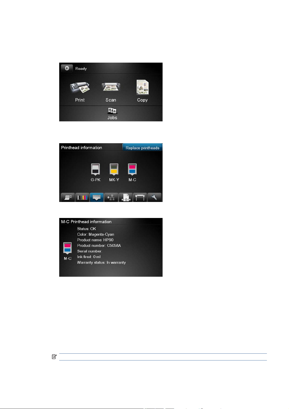
Obtaining Printhead Information
1. Press on the Information icon.
2. Press on the Printhead Menu icon and the following screen is displayed, press on the printhead
that you want information on.
3. The Touch Control Panel displays information on the selected Printhead.
The information supplied is:
●
The current status of the printhead.
●
The color of the printhead.
●
The make of the printhead (HP no.72 is recommended).
●
The product number of the Printhead.
●
The serial number of the Printhead.
●
How much ink has been fired (consumed) by the printhead.
NOTE: It is possible for a printhead to consume more than one Ink Cartridge.
●
The current warranty status of the Printhead.
ENWW Ink-supplies troubleshooting 19
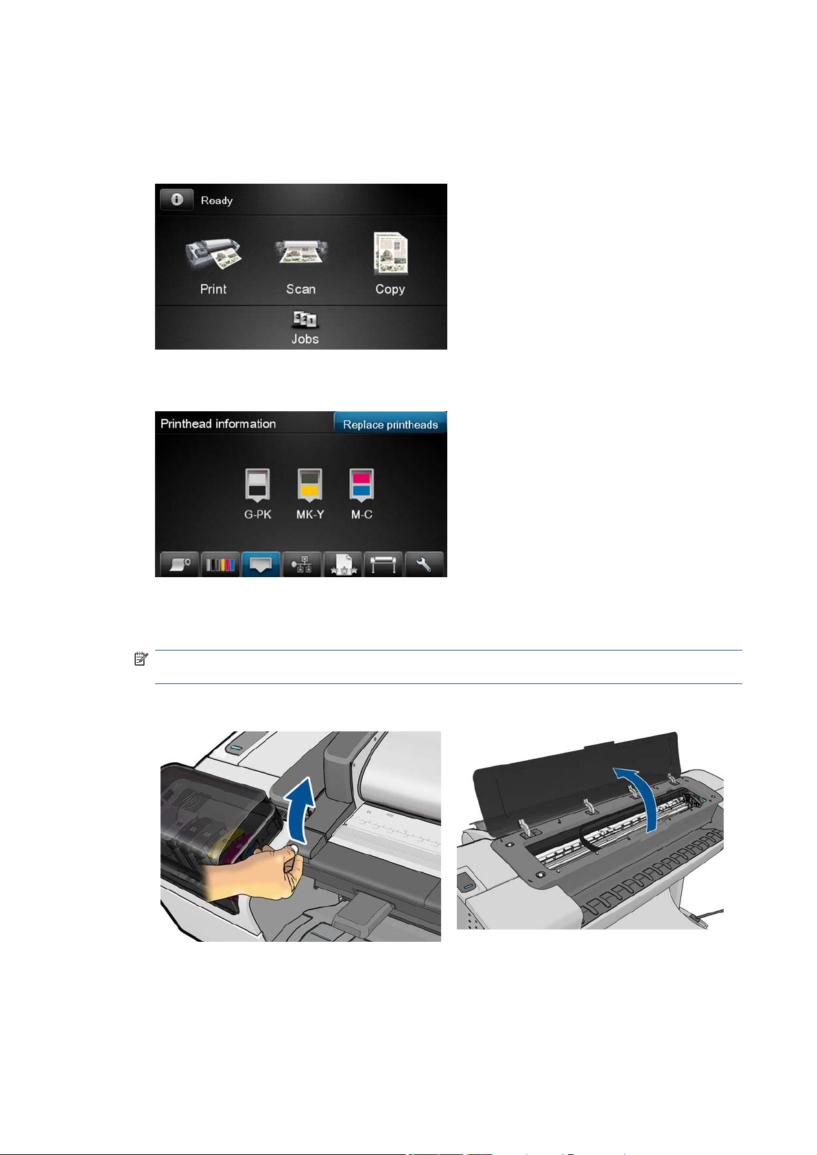
Changing a Printhead
To change a Printhead there are two methods, the first is shown below by using the printhead tab, the
second method is to access the main menu option (refer to the User's Guide for further details).
1. Press on the Information icon.
2. Press on the Printhead Menu icon and the following screen is displayed. Press on the Replace
Printhead tab.
3. A screen is displayed, showing an animation of how to install the printhead(s).
4. The product moves the Carriage to the correct position to replace Printheads.
NOTE: If the carriage is left in the removal position for more than three minutes without inserting
or removing any printheads, it will try to move back to its normal position at the right-hand end.
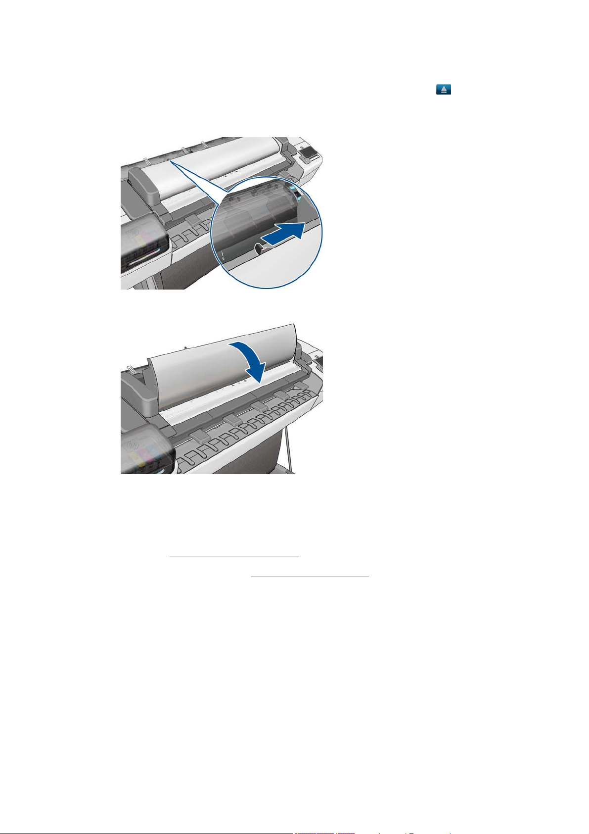
5. Open the Scanner (MFP only) or Window.
6. Locate the carriage on the right side of the product.
20 Chapter 1 Troubleshooting ENWW

7. Pull the blue handle up and toward you to release the Carriage Cover.
8. Push the handle back.
9. This gives you access to the printheads.
10. The following screen is displayed
ENWW Ink-supplies troubleshooting 21
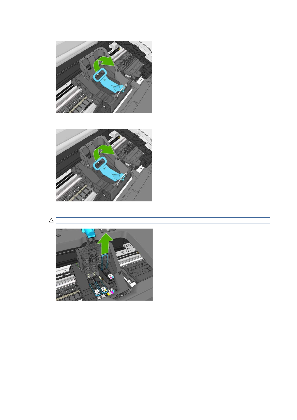
11. Remove a printhead by lifting up the blue handle.
12. Using the blue handle, use steady force to disengage the printhead.
13. Pull the blue handle upward until the printhead is released from the carriage.
CAUTION: Do not pull abruptly because this can damage the printhead.
14. The Touch Control Panel display identifies the missing printhead.
22 Chapter 1 Troubleshooting ENWW

15. To insert a new printhead first remove the orange protective caps.
16. Insert the new printhead into its correct slot in the carriage.
CAUTION: Insert the printhead slowly and vertically, straight down. It may be damaged if you
insert it too fast, or at an angle, or if you rotate it as you insert it.
17. Push down as indicated by the arrow shown below.
CAUTION: When installing the new printhead there may be some resistance, so you need to
press it down firmly but smoothly. You should hear a beep and see confirmation on the Touch
Control Panel display that the printhead has been inserted.
ENWW Ink-supplies troubleshooting 23
Loading...