


 Loading...
Digital Video Recorder
User Manual
UD01394B

Digital Video Recorder User Manual
User Manual
COPYRIGHT ©2016 Hangzhou Hikvision Digital Technology Co., Ltd.
ALL RIGHTS RESERVED.
Any and all information, including, among others, wordings, pictures, graphs are the properties of Hangzhou
Hikvision Digital Technology Co., Ltd. or its subsidiaries (hereinafter referred to be “Hikvision”). This user manual (hereinafter referred to be “the Manual”) cannot be reproduced, changed, translated, or distributed, partially or wholly, by any means, without the prior written permission of Hikvision. Unless otherwise stipulated, Hikvision does not make any warranties, guarantees or representations, express or implied, regarding to the Manual.
About this Manual
This Manual is applicable to Turbo HD Digital Video Recorder (DVR).
The Manual includes instructions for using and managing the product. Pictures, charts, images and all other information hereinafter are for description and explanation only. The information contained in the Manual is subject to change, without notice, due to firmware updates or other reasons. Please find the latest version in the company website (http://overseas.hikvision.com/en/).
Please use this user manual under the guidance of professionals.
Trademarks Acknowledgement
 and other Hikvision’s trademarks and logos are the properties of Hikvision in various jurisdictions.
Other trademarks and logos mentioned below are the properties of their respective owners.
Legal Disclaimer
TO THE MAXIMUM EXTENT PERMITTED BY APPLICABLE LAW, THE PRODUCT DESCRIBED, WITH
ITS HARDWARE, SOFTWARE AND FIRMWARE, IS PROVIDED “AS IS”, WITH ALL FAULTS AND
ERRORS, AND HIKVISION MAKES NO WARRANTIES, EXPRESS OR IMPLIED, INCLUDING WITHOUT LIMITATION, MERCHANTABILITY, SATISFACTORY QUALITY, FITNESS FOR A PARTICULAR PURPOSE, AND NON-INFRINGEMENT OF THIRD PARTY. IN NO EVENT WILL HIKVISION, ITS DIRECTORS, OFFICERS, EMPLOYEES, OR AGENTS BE LIABLE TO YOU FOR ANY SPECIAL, CONSEQUENTIAL, INCIDENTAL, OR INDIRECT DAMAGES, INCLUDING, AMONG OTHERS, DAMAGES FOR LOSS OF BUSINESS PROFITS, BUSINESS INTERRUPTION, OR LOSS OF DATA OR DOCUMENTATION, IN CONNECTION WITH THE USE OF THIS PRODUCT, EVEN IF HIKVISION HAS BEEN ADVISED OF THE POSSIBILITY OF SUCH DAMAGES.
REGARDING TO THE PRODUCT WITH INTERNET ACCESS, THE USE OF PRODUCT SHALL BE WHOLLY AT YOUR OWN RISKS. HIKVISION SHALL NOT TAKE ANY RESPONSIBILITES FOR ABNORMAL OPERATION, PRIVACY LEAKAGE OR OTHER DAMAGES RESULTING FROM CYBER ATTACK, HACKER ATTACK, VIRUS INSPECTION, OR OTHER INTERNET SECURITY RISKS; HOWEVER, HIKVISION WILL PROVIDE TIMELY TECHNICAL SUPPORT IF REQUIRED.
SURVEILLANCE LAWS VARY BY JURISDICTION. PLEASE CHECK ALL RELEVANT LAWS IN YOUR JURISDICTION BEFORE USING THIS PRODUCT IN ORDER TO ENSURE THAT YOUR USE CONFORMS THE APPLICABLE LAW. HIKVISION SHALL NOT BE LIABLE IN THE EVENT THAT THIS PRODUCT IS USED WITH ILLEGITIMATE PURPOSES.
IN THE EVENT OF ANY CONFLICTS BETWEEN THIS MANUAL AND THE APPLICABLE LAW, THE LATER PREVAILS.
1

Digital Video Recorder User Manual
Regulatory Information
FCC Information
Please take attention that changes or modification not expressly approved by the party responsible for compliance could void the user’s authority to operate the equipment.
FCC compliance: This equipment has been tested and found to comply with the limits for a Class A digital device, pursuant to part 15 of the FCC Rules. These limits are designed to provide reasonable protection against harmful interference when the equipment is operated in a commercial environment. This equipment generates, uses, and can radiate radio frequency energy and, if not installed and used in accordance with the instruction manual, may cause harmful interference to radio communications. Operation of this equipment in a residential area is likely to cause harmful interference in which case the user will be required to correct the interference at his own expense.
FCC Conditions
This device complies with part 15 of the FCC Rules. Operation is subject to the following two conditions:
1.This device may not cause harmful interference.
2.This device must accept any interference received, including interference that may cause undesired operation.
EU Conformity Statement
This product and - if applicable - the supplied accessories too are marked with "CE" and comply therefore with the applicable harmonized European standards listed under the EMC Directive
2014/30/EU, the LVD Directive 2014/35/EU, the RoHS Directive 2011/65/EU.
2012/19/EU (WEEE directive): Products marked with this symbol cannot be disposed of as unsorted municipal waste in the European Union. For proper recycling, return this product to your local supplier upon the purchase of equivalent new equipment, or dispose of it at designated collection
points. For more information see: www.recyclethis.info
2006/66/EC (battery directive): This product contains a battery that cannot be disposed of as unsorted municipal waste in the European Union. See the product documentation for specific battery information. The battery is marked with this symbol, which may include lettering to indicate cadmium (Cd), lead (Pb), or mercury (Hg). For proper recycling, return the battery to your supplier or to a
designated collection point. For more information see: www.recyclethis.info
Industry Canada ICES-003 Compliance
This device meets the CAN ICES-3 (A)/NMB-3(A) standards requirements.
2

Digital Video Recorder User Manual
Safety Instruction
These instructions are intended to ensure that user can use the product correctly to avoid danger or property loss.
The precaution measure is divided into “Warnings” and “Cautions”
Warnings: Serious injury or death may occur if any of the warnings are neglected.
Cautions: Injury or equipment damage may occur if any of the cautions are neglected.
|
|
|
|
Warnings |
Follow |
these |
Cautions Follow these precautions |
safeguards to |
prevent |
serious |
to prevent potential injury or |
injury or death. |
|
|
material damage. |
|
|
|
|
Warnings
Proper configuration of all passwords and other security settings is the responsibility of the installer and/or end-user.
In the use of the product, you must be in strict compliance with the electrical safety regulations of the nation and region. Please refer to technical specifications for detailed information.
Input voltage should meet both the SELV (Safety Extra Low Voltage) and the Limited Power Source with 100 to 240 VAC or 12 VDC according to the IEC60950-1 standard. Please refer to technical specifications for detailed information.
Do not connect several devices to one power adapter as adapter overload may cause over-heating or a fire hazard.
Please make sure that the plug is firmly connected to the power socket.
If smoke, odor or noise rise from the device, turn off the power at once and unplug the power cable, and then please contact the service center.
3

Digital Video Recorder User Manual
Preventive and Cautionary Tips
Before connecting and operating your device, please be advised of the following tips:
•Ensure unit is installed in a well-ventilated, dust-free environment.
•Unit is designed for indoor use only.
•Keep all liquids away from the device.
•Ensure environmental conditions meet factory specifications.
•Ensure unit is properly secured to a rack or shelf. Major shocks or jolts to the unit as a result of dropping it may cause damage to the sensitive electronics within the unit.
•Use the device in conjunction with an UPS if possible.
•Power down the unit before connecting and disconnecting accessories and peripherals.
•A factory recommended HDD should be used for this device.
•Improper use or replacement of the battery may result in hazard of explosion. Replace with the same or equivalent type only. Dispose of used batteries according to the instructions provided by the battery manufacturer.
4

Digital Video Recorder User Manual
Applicable Models
This manual is applicable to the models listed in the following table.
Series |
Model |
DS-7100HGHI-E1 |
DS-7104HGHI-E1 |
|
DS-7108HGHI-E1 |
|
DS-7116HGHI-E1 |
DS-7100HGHI-F1 |
DS-7104HGHI-F1 |
|
DS-7108HGHI-F1 |
|
DS-7116HGHI-F1 |
DS-7200HGHI-E1 |
DS-7204HGHI-E1 |
|
DS-7208HGHI-E1 |
|
DS-7216HGHI-E1 |
DS-7200HGHI-E2 |
DS-7208HGHI-E2 |
|
DS-7216HGHI-E2 |
DS-7200HGHI-F1 |
DS-7204HGHI-F1 |
|
DS-7208HGHI-F1 |
|
DS-7216HGHI-F1 |
DS-7200HGHI-F2 |
DS-7208HGHI-F2 |
|
DS-7216HGHI-F2 |
DS-7200HQHI-F1/N |
DS-7204HQHI-F1/N |
|
DS-7208HQHI-F1/N |
|
DS-7216HQHI-F1/N |
DS-7200HQHI-F2/N |
DS-7208HQHI-F2/N |
|
DS-7216HQHI-F2/N |
DS-7100HQHI-F1/N |
DS-7104HQHI-F1/N |
|
DS-7108HQHI-F1/N |
|
DS-7116HQHI-F1/N |
DS-7100HGHI-F1/N |
DS-7104HGHI-F1/N |
|
DS-7108HGHI-F1/N |
|
DS-7116HGHI-F1/N |
DS-7200HGHI-F1/N |
DS-7204HGHI-F1/N |
|
DS-7208HGHI-F1/N |
|
DS-7216HGHI-F1/N |
DS-7200HUHI-F1/N |
DS-7204HUHI-F1/N |
|
DS-7208HUHI-F1/N |
DS-7200HUHI-F2/N |
DS-7204HUHI-F2/N |
|
DS-7208HUHI-F2/N |
|
DS-7216HUHI-F2/N |
DS-7300HQHI-F4/N |
DS-7304HQHI-F4/N |
|
DS-7308HQHI-F4/N |
|
DS-7316HQHI-F4/N |
DS-8100HQHI-F8/N |
DS-8104HQHI-F8/N |
|
DS-8108HQHI-F8/N |
|
DS-8116HQHI-F8/N |
Symbol Conventions
The symbols that may be found in this document are defined as follows.
Symbol Description
Indicates a potentially hazardous situation, which if not avoided, could result in equipment damage, data loss, performance degradation, or unexpected results.
Provides additional information to emphasize or supplement important points of the main text.
5

Digital Video Recorder User Manual
Product Key Features
General
Connectable to HD-TVI and analog cameras;
Support HIKVISION-C protocol for connecting camera over coax;
Connectable to AHD cameras (-F series DVR);
Connectable to IP cameras;
The IP camera connection is not supported by DS-7100 series DVR.
Each channel supports dual-stream. And sub-stream supports up to WD1 resolution;
The main stream of HGHI models support up to 720p resolution, and the HQHI models support up to 1080p lite (960×1080) resolution when 1080p Lite mode is enabled;
The main stream of DS-7200HUHI-F/N series support up to 3MP resolution of all channels;
Independent configuration for each channel, including resolution, frame rate, bit rate, image quality, etc.
Encoding for both video stream and video & audio stream; audio and video synchronization during composite stream encoding;
Support enabling H.264+ to ensure high video quality with lowered bitrate;
Watermark technology.
Local Monitoring
HDMI/VGA output at up to 4K (3840 ×2160) resolution for DS-7116HQHI-F1/N, DS-7216HQHI-F1/N, DS-7216HQHI-F2/N, DS-7208HUHI-F1/N, DS-7208HUHI-F2/N, DS-7216HUHI-F2/N, DS-7300HQHI-F4/N and DS-8100HQHI-F8/N; and up to 1920×1080 resolution for other models;
1/4/6/8/9/16/25-screen live view is supported, and the display sequence of screens is adjustable;
Live view screen can be switched in group and manual switch and automatic cycle live view are also provided, the interval of automatic cycle can be adjusted;
Quick setting menu is provided for live view;
The selected live view channel can be shielded;
Motion detection, video-tampering detection, video exception alarm, video loss alarm and VCA alarm functions;
Privacy mask;
Several PTZ protocols supported; PTZ preset, patrol and pattern;
Zooming in/out by clicking the mouse and PTZ tracing by dragging mouse.
HDD Management
For E1, F1/N and F1 models, 1 SATA hard disk can be connected;
For E2, F2/N and F2 models, up to 2 SATA hard disks can be connected; For F4/N models, up to 4 SATA hard disks can be connected;
And for F8/N models, up to 8 SATA hard disks can be connected;
Each disk with a maximum of 6TB storage capacity;
8 network disks (8 NAS disks, 8 IP SAN disks or n NAS disks + m IP SAN disks (n+m ≤ 8)) can be connected.
Support cloud storage;
Cloud storage is only applicable to HQHI-F/N and HUHI-F/N series DVR.
S.M.A.R.T. and bad sector detection;
6

Digital Video Recorder User Manual
HDD sleeping function;
HDD property: redundancy, read-only, read/write (R/W);
HDD group management;
HDD quota management; different capacity can be assigned to different channels.
Recording and Playback
Holiday recording schedule configuration;
Cycle and non-cycle recording modes;
Normal and event video encoding parameters;
Multiple recording types: manual, continuous, alarm, motion, motion | alarm, motion & alarm and Event;
Support POS triggered recording for DS-7300/8100-HQHI-F/N;
8 recording time periods with separated recording types;
Support Channel-Zero encoding;
Main stream and sub-stream configurable for simultaneous recording;
Pre-record and post-record for motion detection triggered recording, and pre-record time for schedule and manual recording;
Searching record files by events (alarm input/motion detection);
Customization of tags, searching and playing back by tags;
Locking and unlocking of record files;
Local redundant recording;
Searching and playing back record files by camera number, recording type, start time, end time, etc.;
Smart playback to go through less effective information;
Main stream and sub-stream selectable for local/remote playback;
Zooming in for any area when playback;
Multi-channel reverse playback;
Supports pause, fast forward, slow forward, skip forward, and skip backward when playback, locating by dragging the mouse on the progress bar;
4/8/16-ch synchronous playback;
Backup
Export data by a USB, and SATA device;
Export video clips when playback;
Management and maintenance of backup devices.
Alarm and Exception
Configurable arming time of alarm input/output;
Alarm for video loss, motion detection, video tampering, abnormal signal, video input/recording resolution mismatch, illegal login, network disconnected, IP confliction, record exception, HDD error, and HDD full, etc.;
Alarm triggers full screen monitoring, audio alarm, notifying surveillance center, sending email and alarm output;
VCA detection alarm is supported;
 DS-7100 does not support VCA alarm.
Support POS triggered alarm;
Support coaxial alarm;
Automatic restore when system is abnormal.
Other Local Functions
Manual and automatic video quality diagnostics;
Operable by mouse and remote control;
7

Digital Video Recorder User Manual
Three-level user management; admin user can create many operating account and define their operating permission, which includes the permission to access any channel;
Completeness of operation, alarm, exceptions and log writing and searching;
Manually triggering and clearing alarms;
Importing and exporting of configuration file of devices;
Getting cameras type information automatically.
Network Functions
2 self-adaptive 10M/100M/1000M network interfaces for DS-8100HQHI-F/N series, with three working modes configurable: multi-address, load balance, network fault tolerance; and 1 self-adaptive 10M/100M/1000M network interface or 1 self-adaptive 10M/100Mbps network interface provided for other models;
IPv6 is supported;
TCP/IP protocol, PPPoE, DHCP, DNS, DDNS, NTP, SADP, SMTP, NFS, iSCSI, UPnP™ and HTTPS are supported;
Extranet access by HiDDNS;
Support access by EZVIZ Cloud P2P;
TCP, UDP and RTP for unicast;
Auto/Manual port mapping by UPnPTM;
Remote search, playback, download, locking and unlocking the record files, and downloading files broken transfer resume;
Remote parameters setup; remote import/export of device parameters;
Remote viewing of the device status, system logs and alarm status;
Remote keyboard operation;
Remote HDD formatting and program upgrading;
Remote system restart and shutdown;
Support upgrading via remote FTP server;
RS-485 transparent channel transmission;
Alarm and exception information can be sent to the remote host;
Remotely start/stop recording;
Remotely start/stop alarm output;
Remote PTZ control;
Remote JPEG capture;
Two-way audio and voice broadcasting;
Embedded WEB server.
Development Scalability
SDK for Windows and Linux system;
Source code of application software for demo;
Development support and training for application system.
8

Digital Video Recorder User Manual
Table of Contents
Product Key Features ................................................................................................................................. |
6 |
||
Chapter 1 |
|
Introduction ........................................................................................................................ |
12 |
1.1 |
Front Panel .................................................................................................................................... |
13 |
|
1.2 |
IR Remote Control Operations ...................................................................................................... |
20 |
|
1.3 |
USB Mouse Operation .................................................................................................................. |
22 |
|
1.4 |
Input Method Description.............................................................................................................. |
23 |
|
1.5 |
Rear Panel ..................................................................................................................................... |
24 |
|
Chapter 2 |
|
Getting Started ................................................................................................................... |
28 |
2.1 |
Starting Up and Shutting Down the DVR...................................................................................... |
29 |
|
2.2 |
Activating the Device .................................................................................................................... |
30 |
|
2.3 |
Basic Configuration in Startup Wizard .......................................................................................... |
31 |
|
2.3.1 Configuring the Signal Input Channel ................................................................................. |
31 |
||
2.3.2 Using the Wizard for Basic Configuration ........................................................................... |
32 |
||
2.4 |
Login and Logout .......................................................................................................................... |
36 |
|
2.4.3 |
User Login ........................................................................................................................... |
36 |
|
2.4.4 |
User Logout ......................................................................................................................... |
37 |
|
2.5 |
Adding and Connecting the IP Cameras ........................................................................................ |
38 |
|
2.5.1 |
Activating the IP Camera ..................................................................................................... |
38 |
|
2.5.2 Adding the Online IP Cameras............................................................................................. |
39 |
||
2.5.3 Editing the Connected IP Cameras....................................................................................... |
41 |
||
2.6 |
Configuring the Signal Input Channel ........................................................................................... |
43 |
|
Chapter 3 |
|
Live View............................................................................................................................. |
45 |
3.1 |
Introduction of Live View ............................................................................................................. |
46 |
|
3.2 |
Operations in Live View Mode...................................................................................................... |
47 |
|
3.2.1 Using the Mouse in Live View............................................................................................. |
47 |
||
3.2.2 |
Main/Aux Output Switching ................................................................................................ |
48 |
|
3.2.3 Quick Setting Toolbar in Live View Mode .......................................................................... |
48 |
||
3.3 |
Channel-Zero Encoding................................................................................................................. |
51 |
|
3.4 |
Adjusting Live View Settings ........................................................................................................ |
52 |
|
3.5 |
Manual Video Quality Diagnostics................................................................................................ |
53 |
|
Chapter 4 |
|
PTZ Controls ...................................................................................................................... |
54 |
4.1 |
Configuring PTZ Settings.............................................................................................................. |
55 |
|
4.2 |
Setting PTZ Presets, Patrols and Patterns ...................................................................................... |
57 |
|
4.2.1 |
Customizing Presets............................................................................................................. |
57 |
|
4.2.2 |
Calling Presets ..................................................................................................................... |
57 |
|
4.2.3 |
Customizing Patrols ............................................................................................................. |
58 |
|
4.2.4 |
Calling Patrols...................................................................................................................... |
59 |
|
4.2.5 |
Customizing Patterns ........................................................................................................... |
59 |
|
4.2.6 |
Calling Patterns.................................................................................................................... |
60 |
|
4.2.7 Customizing Linear Scan Limit ........................................................................................... |
61 |
||
4.2.8 |
Calling Linear Scan.............................................................................................................. |
61 |
|
4.2.9 |
One-touch Park .................................................................................................................... |
62 |
|
4.3 |
PTZ Control Panel......................................................................................................................... |
63 |
|
Chapter 5 |
|
Recording Settings.............................................................................................................. |
64 |
5.1 |
Configuring Encoding Parameters................................................................................................. |
65 |
|
5.2 |
Configuring Recording Schedule .................................................................................................. |
68 |
|
5.3 |
Configuring Motion Detection Recording ..................................................................................... |
71 |
|
5.4 |
Configuring Alarm Triggered Recording....................................................................................... |
72 |
|
5.5 |
Configuring Event Recording........................................................................................................ |
74 |
|
5.6 |
Configuring Manual Recording ..................................................................................................... |
76 |
|
5.7 |
Configuring Holiday Recording .................................................................................................... |
77 |
|
5.8 |
Configuring Redundant Recording ................................................................................................ |
79 |
|
5.9 |
Configuring HDD Group............................................................................................................... |
81 |
|
5.10 |
Files Protection.............................................................................................................................. |
82 |
|
5.11 |
Configuring 1080P Lite ................................................................................................................. |
84 |
|
Chapter 6 |
|
Playback .............................................................................................................................. |
85 |
6.1 |
Playing Back Record Files ............................................................................................................ |
86 |
|
6.1.1 |
Instant Playback ................................................................................................................... |
86 |
|
6.1.2 Playing Back by Normal Search .......................................................................................... |
86 |
||
6.1.3 Playing Back by Event Search ............................................................................................. |
88 |
||
6.1.4 Playing Back by Tag ............................................................................................................ |
90 |
||
6.1.5 Playing Back by Smart Search ............................................................................................. |
92 |
||
9
Digital Video Recorder User Manual
6.1.6 Playing Back by System Logs.............................................................................................. |
94 |
||
6.1.7 Playing Back by Sub-Periods............................................................................................... |
95 |
||
6.1.8 Playing Back External File .................................................................................................. |
96 |
||
6.2 |
Auxiliary Functions of Playback ................................................................................................... |
97 |
|
6.2.1 Playing Back Frame by Frame ............................................................................................. |
97 |
||
6.2.2 |
Digital Zoom........................................................................................................................ |
97 |
|
6.2.3 Reverse Playback of Multi-channel ..................................................................................... |
97 |
||
Chapter 7 |
|
Backup................................................................................................................................. |
99 |
7.1 |
Backing up Record Files.............................................................................................................. |
100 |
|
7.1.1 Backing up by Normal Video Search ................................................................................. |
100 |
||
7.1.2 Backing up by Event Search .............................................................................................. |
102 |
||
7.1.3 Backing up Video Clips ..................................................................................................... |
103 |
||
7.2 |
Managing Backup Devices .......................................................................................................... |
103 |
|
Chapter 8 |
|
Alarm Settings .................................................................................................................. |
105 |
8.1 |
Setting Motion Detection............................................................................................................. |
106 |
|
8.2 |
Setting Sensor Alarms ................................................................................................................. |
108 |
|
8.3 |
Detecting Video Loss................................................................................................................... |
111 |
|
8.4 |
Detecting Video Tampering ......................................................................................................... |
112 |
|
8.5 |
Setting All-day Video Quality Diagnostics .................................................................................. |
113 |
|
8.6 |
Handling Exceptions ................................................................................................................... |
115 |
|
8.7 |
Setting Alarm Response Actions ................................................................................................. |
117 |
|
Chapter 9 |
|
POS Configuration ........................................................................................................... |
119 |
9.1 |
Configuring POS Settings ........................................................................................................... |
120 |
|
9.2 |
Configuring Overlay Channel...................................................................................................... |
124 |
|
9.3 |
Configuring POS Alarm .............................................................................................................. |
125 |
|
Chapter 10 |
VCA Alarm ....................................................................................................................... |
127 |
|
10.1 |
Face Detection ............................................................................................................................. |
128 |
|
10.2 |
Vehicle Detection......................................................................................................................... |
129 |
|
10.3 |
Line Crossing Detection .............................................................................................................. |
130 |
|
10.4 |
Intrusion Detection ...................................................................................................................... |
132 |
|
10.5 |
Region Entrance Detection .......................................................................................................... |
134 |
|
10.6 |
Region Exiting Detection ............................................................................................................ |
134 |
|
10.7 |
Loitering Detection...................................................................................................................... |
135 |
|
10.8 |
People Gathering Detection......................................................................................................... |
135 |
|
10.9 |
Fast Moving Detection ................................................................................................................ |
135 |
|
10.10 |
Parking Detection ........................................................................................................................ |
135 |
|
10.11 |
Unattended Baggage Detection ................................................................................................... |
136 |
|
10.12 |
Object Removal Detection........................................................................................................... |
136 |
|
10.13 |
Audio Exception Detection ......................................................................................................... |
136 |
|
10.14 |
Defocus Detection ....................................................................................................................... |
137 |
|
10.15 |
PIR Alarm.................................................................................................................................... |
137 |
|
Chapter 11 |
VCA Search....................................................................................................................... |
138 |
|
11.1 |
Face Search.................................................................................................................................. |
139 |
|
11.2 |
Behavior Search .......................................................................................................................... |
140 |
|
11.3 |
Plate Search ................................................................................................................................. |
142 |
|
11.4 |
People Counting .......................................................................................................................... |
142 |
|
11.5 |
Heat Map ..................................................................................................................................... |
144 |
|
Chapter 12 |
Network Settings .............................................................................................................. |
145 |
|
12.1 |
Configuring General Settings ...................................................................................................... |
146 |
|
12.2 |
Configuring Advanced Settings ................................................................................................... |
147 |
|
12.2.1 |
Configuring PPPoE Settings .............................................................................................. |
147 |
|
12.2.2 Configuring EZVIZ Cloud P2P ......................................................................................... |
147 |
||
12.2.3 |
Configuring DDNS ............................................................................................................ |
148 |
|
12.2.4 |
Configuring NTP Server .................................................................................................... |
151 |
|
12.2.5 |
Configuring NAT ............................................................................................................... |
152 |
|
12.2.6 |
Configuring More Settings................................................................................................. |
153 |
|
12.2.7 |
Configuring HTTPS Port ................................................................................................... |
154 |
|
12.2.8 |
Configuring Email ............................................................................................................. |
155 |
|
12.3 |
Checking Network Traffic ........................................................................................................... |
156 |
|
12.4 |
Configuring Network Detection .................................................................................................. |
158 |
|
12.4.1 Testing Network Delay and Packet Loss............................................................................ |
158 |
||
12.4.2 |
Exporting Network Packet ................................................................................................. |
158 |
|
12.4.3 |
Checking Network Status................................................................................................... |
160 |
|
12.4.4 |
Checking Network Statistics .............................................................................................. |
160 |
|
Chapter 13 |
HDD Management............................................................................................................ |
162 |
|
13.1 |
Initializing HDDs ........................................................................................................................ |
163 |
|
13.2 |
Managing Network HDD ............................................................................................................ |
164 |
|
10

Digital Video Recorder User Manual
13.3 |
Managing HDD Group ................................................................................................................ |
166 |
|
|
13.3.1 |
Setting HDD Groups.......................................................................................................... |
166 |
|
13.3.2 |
Setting HDD Property........................................................................................................ |
167 |
13.4 |
Configuring Quota Mode............................................................................................................. |
168 |
|
13.5 |
Configuring Cloud Storage.......................................................................................................... |
169 |
|
13.6 |
Checking HDD Status ................................................................................................................. |
171 |
|
13.7 |
Checking S.M.A.R.T Information ............................................................................................... |
172 |
|
13.8 |
Detecting Bad Sector ................................................................................................................... |
173 |
|
13.9 |
Configuring HDD Error Alarms .................................................................................................. |
174 |
|
Chapter 14 |
Camera Settings................................................................................................................ |
175 |
|
14.1 |
Configuring OSD Settings........................................................................................................... |
176 |
|
14.2 |
Configuring Privacy Mask........................................................................................................... |
177 |
|
14.3 |
Configuring Video Parameters..................................................................................................... |
178 |
|
Chapter 15 |
DVR Management and Maintenance ............................................................................. |
179 |
|
15.1 |
Viewing System Information ....................................................................................................... |
180 |
|
15.2 |
Searching Log Files ..................................................................................................................... |
180 |
|
15.3 |
Importing/Exporting IP Camera Info ........................................................................................... |
183 |
|
15.4 |
Importing/Exporting Configuration Files .................................................................................... |
184 |
|
15.5 |
Upgrading System ....................................................................................................................... |
185 |
|
|
15.5.1 Upgrading by Local Backup Device .................................................................................. |
185 |
|
|
15.5.2 |
Upgrading by FTP ............................................................................................................. |
185 |
15.6 |
Restoring Default Settings........................................................................................................... |
186 |
|
Chapter 16 |
Others................................................................................................................................ |
187 |
|
16.1 |
Configuring General Settings ...................................................................................................... |
188 |
|
16.2 |
Configuring RS-232 Serial Port................................................................................................... |
189 |
|
16.3 |
Configuring DST Settings ........................................................................................................... |
190 |
|
16.4 |
Configuring More Settings .......................................................................................................... |
191 |
|
16.5 |
Managing User Accounts............................................................................................................. |
192 |
|
|
16.5.1 |
Adding a User .................................................................................................................... |
192 |
|
16.5.2 |
Deleting a User .................................................................................................................. |
194 |
|
16.5.3 |
Editing a User .................................................................................................................... |
195 |
Chapter 17 |
Appendix ........................................................................................................................... |
196 |
|
17.1 |
Specifications .............................................................................................................................. |
197 |
|
|
DS-7100HGHI-E1 ......................................................................................................................... |
197 |
|
|
DS-7200HGHI-E1 ......................................................................................................................... |
198 |
|
|
DS-7200HGHI-E2 ......................................................................................................................... |
199 |
|
|
DS-7100HGHI-F1.......................................................................................................................... |
200 |
|
|
DS-7200HGHI-F1.......................................................................................................................... |
201 |
|
|
DS-7200HGHI-F2.......................................................................................................................... |
202 |
|
|
DS-7100HQHI-F1/N...................................................................................................................... |
203 |
|
|
DS-7200HQHI-F1/N...................................................................................................................... |
204 |
|
|
DS-7200HQHI-F2/N...................................................................................................................... |
205 |
|
|
DS-7100HGHI-F1/N...................................................................................................................... |
206 |
|
|
DS-7200HGHI-F1/N...................................................................................................................... |
207 |
|
|
DS-7200HUHI-F1/N...................................................................................................................... |
208 |
|
|
DS-7200HUHI-F2/N...................................................................................................................... |
209 |
|
|
DS-7300HQHI-F4/N...................................................................................................................... |
210 |
|
|
DS-8100HQHI-F8/N...................................................................................................................... |
211 |
|
17.2 |
Glossary....................................................................................................................................... |
212 |
|
17.3 |
Troubleshooting........................................................................................................................... |
213 |
|
17.4 |
Summary of Changes .................................................................................................................. |
216 |
|
17.5 |
List of Compatible Hikvision IP Cameras ................................................................................... |
217 |
|
17.6 |
List of Compatible Third-party IP Cameras................................................................................. |
218 |
|
11

Digital Video Recorder User Manual
Chapter 1 Introduction
12
Digital Video Recorder User Manual
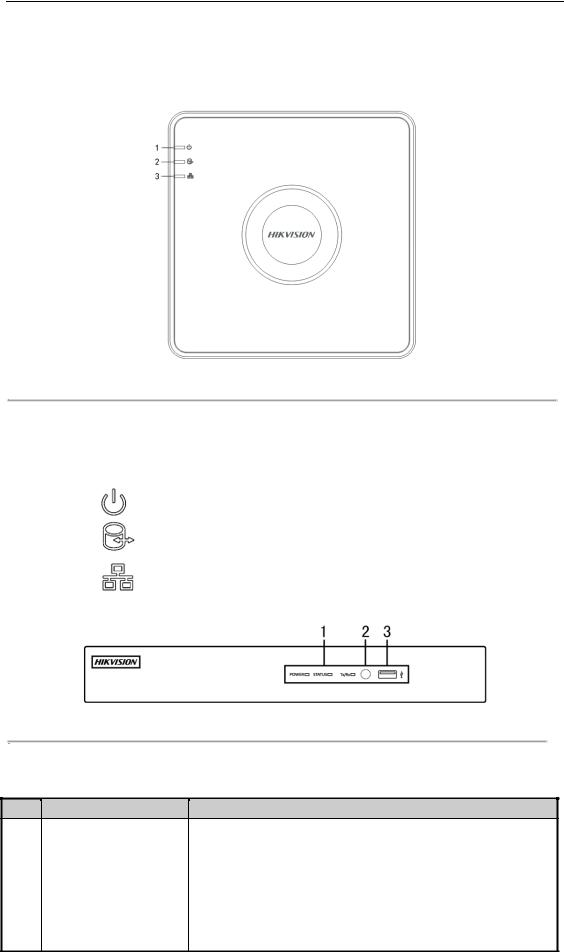
1.1 Front Panel
Front Panel 1:
Figure 1. 1 Front Panel of DS-7100
Please refer to Table 1.1 for the description of the front panel of DS-7100 series DVR.
Table 1. 1 Description of Front Panel
|
No. |
|
|
Icon |
|
|
Description |
|
|
|
|
|
|
|
|||
|
|
|
|
|
|
|
|
|
|
1 |
|
|
|
|
|
Turns red when DVR is powered up. |
|
|
|
|
|
|
|
|
|
|
|
2 |
|
|
|
|
|
Turns red when data is being read from or written to HDD. |
|
|
|
|
|
|
|
|
|
|
|
3 |
|
|
|
|
|
Flickers blue when network connection is functioning properly. |
|
|
|
|
|
|
|
|
|
|
Front Panel 2:
Figure 1. 2 Front Panel of DS-7200HQHI and DS-7200HGHI
Please refer to Table 1.2 for the description of the front panel of DS-7200HQHI and DS-7200HGHI series DVR. Table 1. 2 Description of Front Panel
No. |
Name |
Function Description |
|
|
|
|
|
POWER |
|
Turns yellow when the power switch on the rear panel is turned on. |
|
|
1 |
|
|
STATUS |
|
Flickers red when data is being read from or written to HDD. |
|
|
|
|
|
Tx/Rx |
|
Flickers yellow when network connection is functioning properly. |
|
|
|
|
|
|
|
|
|
|
|
|
|
|
|
|
|
|
2 |
|
|
IR Receiver |
|
Receiver for IR remote |
|
|
|
|
|
|
||
|
|
|
|
|
|
|
|
|
|
3 |
|
|
USB Interfaces |
|
Universal Serial Bus (USB) ports for additional devices such as USB |
|
|
|
|
|
mouse and USB Hard Disk Drive (HDD). |
||
|
|
|
|
|
|
|
13

Digital Video Recorder User Manual
Front Panel 3:
Figure 1. 3 Front Panel of DS-7200HUHI-F/N
|
|
|
|
|
|
|
Table 1. 3 Description of Front Panel |
||||
|
|
|
|
|
|
|
|
|
|
|
|
|
No. |
|
|
|
Name |
|
|
Function Description |
|
||
|
|
|
|
POWER |
|
|
Turns yellow when the device s running. |
||||
|
1 |
|
|
STATUS |
|
|
Flickers red when data is being read from or written to HDD, and |
||||
|
|
|
|
|
turns yellow when the SHIFT function is realized. |
||||||
|
|
|
|
|
|
|
|
|
|||
|
|
|
|
|
|
|
|
|
|
||
|
|
|
|
|
Tx/Rx |
|
|
Flickers yellow when network connection is functioning properly. |
|||
|
|
|
|
|
|
|
|||||
|
|
|
|
|
|
|
|
|
|||
|
|
|
|
|
|
|
|
|
|
|
|
|
|
|
|
|
|
|
SHIFT |
|
|
Switches between the numeric or letter input and functions of the |
|
|
|
|
|
|
|
|
|
|
composite keys. |
||
|
|
|
|
|
|
|
|
|
|
||
|
|
|
|
|
|
|
1/MENU |
|
|
Enters numeral “1”; |
|
|
|
|
|
|
|
|
|
|
Accesses the main menu interface. |
||
|
|
|
|
|
|
|
|
|
|
||
|
|
|
|
|
|
|
|
|
|
Enters numeral “2”; |
|
|
|
|
|
|
|
|
|
|
|
Enters letters “ABC”; |
|
|
|
|
|
|
|
|
|
|
|
Uses the F1 button to select all items in a list field; |
|
|
|
|
|
|
|
|
2/ABC/F1 |
|
|
Turns on/off PTZ light in PTZ Control mode, and use it to zoom |
|
|
|
|
|
|
|
|
|
|
|
out the image; |
|
|
|
|
|
|
|
|
|
|
|
Switches between main and spot video output in live view or |
|
|
|
|
|
|
|
|
|
|
|
playback mode. |
|
|
|
|
|
|
|
|
|
|
|
Enters numeral “3”; |
|
|
|
|
|
|
|
|
3/DEF/F2 |
|
|
Enters letters “DEF”; |
|
|
|
|
|
|
|
|
|
|
Uses the F2 button to change the tab pages; |
||
|
|
|
|
|
|
|
|
|
|
||
|
|
|
|
|
|
|
|
|
|
Zooms in the image in PTZ control mode. |
|
|
|
|
|
|
|
|
|
|
|
Enters numeral “4”; |
|
|
|
|
|
|
|
|
|
|
|
||
|
2 |
|
|
Composite |
|
|
4/GHI/ESC |
|
|
Enters letters “GHI”; |
|
|
|
|
Keys |
|
|
|
|
|
Exits and back to the previous menu. |
||
|
|
|
|
|
|
|
|
|
|||
|
|
|
|
|
|
|
|
|
|
Enters numeral “5”; |
|
|
|
|
|
|
|
|
|
|
|
||
|
|
|
|
|
|
|
|
|
|
Enters letters “JKL”; |
|
|
|
|
|
|
|
|
5/JKL/EDIT |
|
|
Deletes characters before cursor; |
|
|
|
|
|
|
|
|
|
|
|
Checks the checkbox and select the ON/OFF switch; |
|
|
|
|
|
|
|
|
|
|
|
Starts/stops record clipping in playback. |
|
|
|
|
|
|
|
|
|
|
|
Enters numeral “6”; |
|
|
|
|
|
|
|
|
6/MNO/PLAY |
|
|
Enters letters “MNO”; |
|
|
|
|
|
|
|
|
|
|
|
Accesses to playback interface in Playback mode. |
|
|
|
|
|
|
|
|
|
|
|
Enters numeral “7”; |
|
|
|
|
|
|
|
|
7/PQRS/REC |
|
|
Enters letters “PQRS”; |
|
|
|
|
|
|
|
|
|
|
Accesses to manual record interface; |
||
|
|
|
|
|
|
|
|
|
|
||
|
|
|
|
|
|
|
|
|
|
Manually enables/disables record. |
|
|
|
|
|
|
|
|
|
|
|
Enters numeral “8”; |
|
|
|
|
|
|
|
|
8/TUV/PTZ |
|
|
Enters letters “TUV”; |
|
|
|
|
|
|
|
|
|
|
|
Accesses PTZ control interface. |
|
|
|
|
|
|
|
|
9/WXYZ/PREV |
|
|
Enters numeral “9”; |
|
14
Digital Video Recorder User Manual
|
No. |
|
|
Name |
|
|
Function Description |
|
|
|
|
|
|
|
|
||||
|
|
|
|
|
|
|
|
Enters letters “WXYZ”; |
|
|
|
|
|
|
|
|
|
Multi-channel display in live view. |
|
|
|
|
|
|
|
|
|
Enters numeral “0”; |
|
|
|
|
|
|
0/A |
|
|
Shifts the input methods in the editing text field. (Upper and |
|
|
|
|
|
|
|
|
|
lowercase, alphabet, symbols or numeric input). |
|
|
|
|
|
|
|
|
|
|
|
|
|
|
|
|
|
|
|
Navigates between different fields and items in menus. |
|
|
|
|
|
|
|
|
|
|
|
|
|
|
|
|
|
|
|
Uses the Up and Down buttons to speed up and slow down the |
|
|
|
|
|
DIRECTION |
|
|
playing of video files in Playback mode. |
||
|
|
|
|
|
|
The Left and Right button will select the next and previous |
|||
|
|
|
|
|
|
|
|
||
|
|
|
|
|
|
|
|
record files. |
|
|
|
|
|
|
|
|
|
Cycles through channels in Live View mode. |
|
|
3 |
|
|
|
|
|
|
Controls the movement of the PTZ camera in PTZ control mode. |
|
|
|
|
|
|
|
|
|
Confirms selection in any of the menu modes. |
|
|
|
|
|
|
|
|
|
||
|
|
|
|
|
|
|
|
|
|
|
|
|
|
|
|
|
|
Checks the checkbox. |
|
|
|
|
|
|
|
|
|
|
|
|
|
|
|
ENTER |
|
|
Plays or pauses the playing of video files in Playback mode. |
||
|
|
|
|
|
|
|
|
||
|
|
|
|
|
|
|
|
Advances the video by a single frame in single-frame Playback |
|
|
|
|
|
|
|
|
|
mode. |
|
|
|
|
|
|
|
|
|
Stops/starts auto switch in Auto-switch mode. |
|
|
4 |
|
|
USB Interface |
|
|
Universal Serial Bus (USB) ports for additional devices such as |
||
|
|
|
|
|
|||||
|
|
|
|
|
USB mouse and USB Hard Disk Drive (HDD). |
||||
|
|
|
|
|
|
|
|
||
|
5 |
|
|
IR Receiver |
|
|
Receiver for IR remote control. |
||
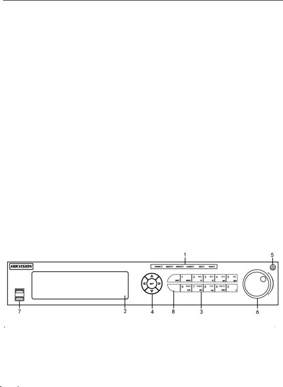
Front Panel 4:
|
|
|
|
|
|
|
Figure 1. 4 Front Panel of DS-7300HQHI-F/N |
||||
|
|
|
|
|
|
|
|
|
|
|
|
|
|
|
|
|
|
|
|
Table 1. 4 Description of Front Panel |
|||
|
|
|
|
|
|
|
|
|
|
|
|
|
No. |
|
|
|
Name |
|
|
Function Description |
|||
|
|
|
|
POWER |
|
|
Turns green when DVR is powered up. |
||||
|
|
|
|
READY |
|
|
Turns green, indicating that the DVR is functioning properly. |
||||
|
|
|
|
|
|
|
|
|
|
Turns blue when device is controlled by an IR remote. |
|
|
|
|
|
STATUS |
|
|
|
|
|||
|
1 |
|
|
|
|
Turns red when controlled by a keyboard and purple when IR remote |
|||||
|
|
|
|
|
|
|
|
|
|||
|
|
|
|
|
|
|
|
|
and keyboard is used at the same time. |
||
|
|
|
|
|
|
|
|
|
|
||
|
|
|
|
ALARM |
|
|
Turns red when a sensor alarm is detected. |
||||
|
|
|
|
|
HDD |
|
|
Flickers in red when data is being read from or written to HDD. |
|||
|
|
|
|
|
Tx/Rx |
|
|
Flickers in green when network connection is functioning properly. |
|||
|
|
|
|
|
|
|
|
|
|||
|
2 |
|
|
DVD-R/W |
|
|
Slot for DVD-R/W. |
||||
|
|
|
|
Composite |
|
|
|
|
|
Switches between the numeric or letter input and functions of the |
|
|
3 |
|
|
|
|
SHIFT |
|
|
composite keys. (Input letter or numbers when the light is out; Realize |
||
|
|
|
Keys |
|
|
|
|
||||
|
|
|
|
|
|
|
|
|
functions when the light is red.) |
||
|
|
|
|
|
|
|
|
|
|
||
15

No.
4
Digital Video Recorder User Manual
|
|
Name |
|
|
Function Description |
||
|
|
|
|
1/MENU |
|
|
Enters numeral “1”; |
|
|
|
|
|
|
Accesses the main menu interface. |
|
|
|
|
|
|
|
|
|
|
|
|
|
|
|
|
Enters numeral “2”; |
|
|
|
|
|
|
|
Enters letters “ABC”; |
|
|
|
|
|
|
|
The F1 button when used in a list field will select all items in the list; |
|
|
|
|
2/ABC/F1 |
|
|
Turns on/off PTZ light in PTZ Control mode, and use it to zoom out the |
|
|
|
|
|
|
|
image; |
|
|
|
|
|
|
|
Switches between main and spot video output in live view or playback |
|
|
|
|
|
|
|
mode. |
|
|
|
|
|
|
|
Enters numeral “3”; |
|
|
|
|
3/DEF/F2 |
|
|
Enters letters “DEF”; |
|
|
|
|
|
|
Uses the F2 button is used to change the tab pages; |
|
|
|
|
|
|
|
|
|
|
|
|
|
|
|
|
Zooms in the image in PTZ control mode. |
|
|
|
|
|
|
|
Enters numeral “4”; |
|
|
|
|
4/GHI/ESC |
|
|
Enters letters “GHI”; |
|
|
|
|
|
|
|
Exits and back to the previous menu. |
|
|
|
|
|
|
|
Enters numeral “5”; |
|
|
|
|
|
|
|
Enters letters “JKL”; |
|
|
|
|
5/JKL/EDIT |
|
|
Deletes characters before cursor; |
|
|
|
|
|
|
|
Check the checkbox and select the ON/OFF switch; |
|
|
|
|
|
|
|
Starts/stops record clipping in playback. |
|
|
|
|
|
|
|
Enters numeral “6”; |
|
|
|
|
6/MNO/PLAY |
|
|
Enters letters “MNO”; |
|
|
|
|
|
|
|
Accesses to playback interface in Playback mode. |
|
|
|
|
|
|
|
Enters numeral “7”; |
|
|
|
|
7/PQRS/REC |
|
|
Enters letters “PQRS”; |
|
|
|
|
|
|
Accesses to manual record interface; |
|
|
|
|
|
|
|
|
|
|
|
|
|
|
|
|
Manually enables/disables record. |
|
|
|
|
|
|
|
Enters numeral “8”; |
|
|
|
|
8/TUV/PTZ |
|
|
Enters letters “TUV”; |
|
|
|
|
|
|
|
Accesses PTZ control interface. |
|
|
|
|
|
|
|
Enters numeral “9”; |
|
|
|
|
9/WXYZ/PREV |
|
|
Enters letters “WXYZ”; |
|
|
|
|
|
|
|
Multi-channel display in live view. |
|
|
|
|
|
|
|
Enters numeral “0”; |
|
|
|
|
0/A |
|
|
Shifts the input methods in the editing text field. (Upper and lowercase, |
|
|
|
|
|
|
|
alphabet, symbols or numeric input). |
|
|
|
|
|
|
|
Navigates between different fields and items in menus. |
|
|
|
|
|
|
|
|
|
|
|
|
|
|
|
|
|
|
|
|
|
|
|
Uses the Up and Down buttons to speed up and slow down the playing |
|
|
DIRECTION |
|
|
of video files in Playback mode. |
||
|
|
|
|
|
|||
|
|
|
|
|
|
|
The Left and Right button will select the next and previous record files. |
|
|
|
|
|
|
|
Cycles through channels in Live View mode. |
|
|
|
|
|
|
|
Controls the movement of the PTZ camera in PTZ control mode. |
|
|
|
|
|
|
|
Confirms selection in any of the menu modes. |
|
|
ENTER |
|
|
|
||
|
|
|
|
Checks the checkbox. |
|||
|
|
|
|
|
|
|
|
|
|
|
|
|
|
|
|
16
|
|
|
|
|
|
Digital Video Recorder User Manual |
|
||
|
|
|
|
|
|
|
|
|
|
|
|
No. |
|
|
Name |
|
|
Function Description |
|
|
|
|
|
|
|
|
|
Plays or pauses the playing of video files in Playback mode. |
|
|
|
|
|
|
|
|
|
|
|
|
|
|
|
|
|
|
|
Advances the video by a single frame in single-frame Playback mode. |
|
|
|
|
|
|
|
|
|
|
|
|
|
|
|
|
|
|
|
Stops/starts auto switch in Auto-switch mode. |
|
|
|
|
|
POWER |
|
|
Power on/off switch. |
|
|
|
|
5 |
|
|
|
|
|
||
|
|
|
|
|
|
|
|
Moves the active selection up and down in a menu. |
|
|
|
|
|
|
|
|
|
|
|
|
|
|
|
|
|
|
|
Cycles through different channels in live view mode. |
|
|
|
6 |
|
|
JOG SHUTTLE Control |
|
|
Jumps 30s forward/backward in video files in the playback mode. |
|
|
|
|
|
|
|
|
|
Controls the movement of the PTZ camera in PTZ control mode. |
|
|
|
|
|
|
|
|
|
Moves the active selection up and down in a menu. |
|
|
|
7 |
|
|
USB Interface |
|
|
Universal Serial Bus (USB) ports for additional devices such as USB |
|
|
|
|
|
|
|
mouse and USB Hard Disk Drive (HDD). |
|
||
|
|
|
|
|
|
|
|
|
|
|
|
8 |
|
|
IR Receiver |
|
|
Receiver for IR remote control. |
|
|
|
|
|
|
|
|
|
|
|
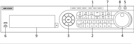
Front Panel 4:
Figure 1. 5 Front Panel of DS-8100HQHI-F/N
|
|
|
|
|
|
|
Table 1. 5 Description of Front Panel |
||||
|
|
|
|
|
|
|
|
|
|
|
|
|
No. |
|
|
|
Name |
|
|
Function Description |
|
||
|
|
|
|
|
|
|
ALARM |
|
|
Turns red when a sensor alarm is detected. |
|
|
|
|
|
|
|
|
READY |
|
|
Turns green, indicating that the DVR is functioning properly. |
|
|
|
|
|
|
|
|
|
|
|
Turns blue when device is controlled by an IR remote. |
|
|
|
|
|
|
|
|
STATUS |
|
|
|
|
|
|
|
|
|
|
|
|
|
Turns red when controlled by a keyboard and purple when IR remote |
||
|
|
|
|
|
|
|
|
|
|
||
|
1 |
|
|
Status |
|
|
|
|
|
and keyboard is used at the same time. |
|
|
|
|
|
|
|
|
|
|
|
||
|
|
|
|
|
HDD |
|
|
Flickers in red when data is being read from or written to HDD. |
|||
|
|
|
Indicators |
|
|
|
|
||||
|
|
|
|
|
|
Tx/Rx |
|
|
Flickers in green when network connection is functioning properly. |
||
|
|
|
|
|
|
|
|
|
|||
|
|
|
|
|
|
|
|
|
|
Turns blue when the device is in armed status; at this time, an alarm |
|
|
|
|
|
|
|
|
|
|
|
is enabled when an event is detected. |
|
|
|
|
|
|
|
|
GUARD |
|
|
Turns off when the device is unarmed. The arm/disarm status can be |
|
|
|
|
|
|
|
|
|
|
|
changed by pressing and holding on the ESC button for more than 3 |
|
|
|
|
|
|
|
|
|
|
|
seconds in live view mode. |
|
|
|
|
|
|
|
|
|
|
|
|
|
|
|
|
|
|
|
|
|
|
|
Switches to the corresponding channel in live view or PTZ control |
|
|
|
|
|
|
|
|
|
|
|
mode. |
|
|
|
|
|
|
|
|
|
|
|
Inputs numbers and characters in edit mode. |
|
|
2 |
|
|
Alphanumeric Buttons |
|
|
Switches between different channels in playback mode. |
||||
|
|
|
|
|
|
|
|
|
|
Turns blue when the corresponding channel is recording; turns red |
|
|
|
|
|
|
|
|
|
|
|
when the channel is in network transmission status; turns pink when |
|
|
|
|
|
|
|
|
|
|
|
the channel is recording and transmitting. |
|
17

Digital Video Recorder User Manual
|
No. |
|
|
|
Name |
|
|
Function Description |
|
||
|
|
|
|
|
|
|
|||||
|
|
|
|
|
|
|
|
|
|
Navigates between different fields and items in menus. |
|
|
|
|
|
|
|
|
|
|
|
Uses the Up and Down buttons to speed up and slow down the |
|
|
|
|
|
|
|
|
|
|
|
playing of video files in Playback mode. |
|
|
|
|
|
|
|
|
DIRECTION |
|
|
The Left and Right button will select the next and previous record |
|
|
|
|
|
|
|
|
|
|
|
files. |
|
|
|
|
|
Control |
|
|
|
|
|
Cycles through channels in Live View mode. |
|
|
3 |
|
|
|
|
|
|
|
Controls the movement of the PTZ camera in PTZ control mode. |
||
|
|
|
Buttons |
|
|
|
|
|
|||
|
|
|
|
|
|
|
|
|
Confirms selection in any of the menu modes. |
||
|
|
|
|
|
|
|
|
|
|
||
|
|
|
|
|
|
|
|
|
|
Checks the checkbox. |
|
|
|
|
|
|
|
|
ENTER |
|
|
Plays or pauses the playing of video files in Playback mode. |
|
|
|
|
|
|
|
|
|
|
Advances the video by a single frame in single-frame Playback |
||
|
|
|
|
|
|
|
|
|
|
||
|
|
|
|
|
|
|
|
|
|
mode. |
|
|
|
|
|
|
|
|
|
|
|
Stops/starts auto switch in Auto-switch mode. |
|
|
|
|
|
|
|
|
|
|
|
Moves the active selection up and down in a menu. |
|
|
|
|
|
|
|
|
|
|
|
||
|
4 |
|
|
JOG SHUTTLE Control |
|
|
Cycles through different channels in live view mode. |
||||
|
|
|
|
|
Jumps 30s forward/backward in video files in the playback mode. |
||||||
|
|
|
|
|
|
|
|
|
|
||
|
|
|
|
|
|
|
|
|
|
Controls the movement of the PTZ camera in PTZ control mode. |
|
|
5 |
|
|
POWER |
|
|
Power on/off switch. |
||||
|
6 |
|
|
USB Interfaces |
|
|
Universal Serial Bus (USB) ports for additional devices such as USB |
||||
|
|
|
|
|
|||||||
|
|
|
|
|
mouse and USB Hard Disk Drive (HDD). |
||||||
|
|
|
|
|
|
|
|
|
|
||
|
|
|
|
|
|
|
ESC |
|
|
Returns to the previous menu. |
|
|
|
|
|
|
|
|
|
|
Presses for arming/disarming the device in live view mode. |
||
|
|
|
|
|
|
|
|
|
|
||
|
|
|
|
|
|
|
|
|
|
Enters the Manual Record settings menu. |
|
|
|
|
|
|
|
|
REC/SHOT |
|
|
Presses this button followed by a numeric button to call a PTZ preset |
|
|
|
|
|
|
|
|
|
|
in PTZ control settings. |
||
|
|
|
|
|
|
|
|
|
|
||
|
|
|
|
|
|
|
|
|
|
Turns audio on/off in the playback mode. |
|
|
|
|
|
|
|
|
PLAY/AUTO |
|
|
Enters the playback mode. |
|
|
|
|
|
|
|
|
|
|
Automatically scans in the PTZ control menu. |
||
|
|
|
|
|
|
|
|
|
|
||
|
|
|
|
|
|
|
ZOOM+ |
|
|
Zooms in the PTZ camera in the PTZ control setting. |
|
|
|
|
|
|
|
|
|
|
|
Adjusts focus in the PTZ Control menu. |
|
|
|
|
|
|
|
|
|
|
|
||
|
|
|
|
|
|
|
A/FOCUS+ |
|
|
Switches between input methods (upper and lower case alphabet, |
|
|
|
|
|
|
|
|
|
|
|
symbols and numeric input). |
|
|
7 |
|
|
Composite |
|
|
|
Edits text fields. When editing text fields, it also deletes the character |
|||
|
|
|
Keys |
|
|
|
|
|
in front of the cursor. |
||
|
|
|
|
|
|
|
|||||
|
|
|
|
|
|
|
EDIT/IRIS+ |
|
|
Checks the checkbox in the checkbox fields. |
|
|
|
|
|
|
|
|
|
|
Adjusts the iris of the camera in PTZ control mode. |
||
|
|
|
|
|
|
|
|
|
|
||
|
|
|
|
|
|
|
|
|
|
Generates video clips for backup in playback mode. |
|
|
|
|
|
|
|
|
|
|
|
Enters/exits the folder of USB device and eSATA HDD. |
|
|
|
|
|
|
|
|
|
|
Switches between main and spot output. |
||
|
|
|
|
|
|
|
MAIN/SPOT/Z |
|
|
||
|
|
|
|
|
|
|
OOM- |
|
|
Zooms out the image in PTZ control mode. |
|
|
|
|
|
|
|
|
|
|
|
Selects all items on the list when used in a list field. |
|
|
|
|
|
|
|
|
F1/ LIGHT |
|
|
Turns on/off PTZ light (if applicable) in PTZ control mode. |
|
|
|
|
|
|
|
|
|
|
|
|
|
|
|
|
|
|
|
|
|
|
|
Switches between play and reverse play in playback mode. |
|
|
|
|
|
|
|
|
F2/ AUX |
|
|
Cycles through tab pages. |
|
|
|
|
|
|
|
|
|
|
Switches between channels in synchronous playback mode. |
||
|
|
|
|
|
|
|
|
|
|
||
|
|
|
|
|
|
|
MENU/WIPER |
|
|
Returns to the Main menu (after successful login). |
|
|
|
|
|
|
|
|
|
|
|
|
|
18
|
|
|
|
|
|
Digital Video Recorder User Manual |
|||
|
|
|
|
|
|
|
|
|
|
|
No. |
|
Name |
|
|
|
Function Description |
||
|
|
|
|
|
|
|
|
|
Presses and holds the button for five seconds to turn off audible key |
|
|
|
|
|
|
|
|
|
beep. |
|
|
|
|
|
|
|
|
|
Starts wiper (if applicable) in PTZ control mode. |
|
|
|
|
|
|
|
|
|
Shows/hides the control interface in playback mode. |
|
|
|
|
|
|
|
|
|
Switches between single screen and multi-screen mode. |
|
|
|
|
|
PREV/FOCUS- |
|
Adjusts the focus in conjunction with the A/FOCUS+ button in PTZ |
||
|
|
|
|
|
|
|
|
|
control mode. |
|
|
|
|
|
PTZ/IRIS- |
|
|
|
Enters the PTZ Control mode. |
|
|
|
|
|
|
|
|
Adjusts the iris of the PTZ camera in PTZ control mode. |
|
|
|
|
|
|
|
|
|
|
|
|
|
|
IR Receiver |
|
|
|
Receiver for IR remote control. |
||
|
8 |
|
|
|
|
||||
|
9 |
|
DVD-R/W |
|
|
|
Slot for DVD-R/W. |
||
19
Digital Video Recorder User Manual
1.2 IR Remote Control Operations
The DVR may also be controlled with the included IR remote control, shown in Figure 1. 6.
Batteries (2×AAA) must be installed before operation.
Figure 1. 6 Remote Control
The keys on the remote control closely resemble the ones found on the front panel. Refer to Table 1. 6, they include:
|
|
|
|
|
|
|
Table 1. 6 Description of the IR Remote Control Buttons |
|
No. |
|
|
Name |
|
|
Description |
|
|
|
|
|
|
|
|
|
|
|
|
|
|
|
Power on/off the device. |
|
1 |
|
|
POWER |
|
|
|
|
|
|
|
|
Power on/off the device by pressing and holding the button for 5 seconds. |
||
|
|
|
|
|
|
|
|
|
|
|
|
|
|
|
|
|
|
|
|
|
|
|
Press the button to return to the main menu (after successful login). |
|
|
|
|
|
|
|
|
|
|
|
|
|
|
|
Press and hold the button for 5 seconds will turn off audible key beep. |
|
2 |
|
|
MENU Button |
|
|
|
|
|
|
|
|
In PTZ Control mode, the MENU button will start wiper (if applicable). |
||
|
|
|
|
|
|
|
|
|
|
|
|
|
|
|
|
|
|
|
|
|
|
|
In Playback mode, it is used to show/hide the control interface. |
|
|
|
|
|
|
|
|
|
|
|
|
|
|
|
Enter the Manual Record setting menu. |
|
|
|
|
|
|
|
|
|
3 |
|
|
REC Button |
|
|
In PTZ control settings, press the button and then you can call a PTZ preset |
|
|
|
|
|
by pressing Numeric button. |
||
|
|
|
|
|
|
|
|
|
|
|
|
|
|
|
It is also used to turn audio on/off in the Playback mode. |
|
|
|
|
|
|
||
|
4 |
|
|
DIRECTION Button |
|
|
Navigate between different fields and items in menus. |
|
|
|
|
|
|
|
|
20

|
|
|
|
|
|
|
|
Digital Video Recorder User Manual |
|
|
|
|
|
|
|
|
|
|
|
|
|
No. |
|
|
Name |
|
|
Description |
|
|
|
|
|
|
|
|
|
|
|
|
|
|
|
|
|
|
|
In the Playback mode, the Up and Down button is used to speed up and |
|
|
|
|
|
|
|
|
|
slow down recorded video. The Left and Right button will select the next |
|
|
|
|
|
|
|
|
|
and previous record files. |
|
|
|
|
|
|
|
|
|
In Live View mode, these buttons can be used to cycle through channels. |
|
|
|
|
|
|
|
|
|
|
|
|
|
|
|
|
|
|
|
In PTZ control mode, it can control the movement of the PTZ camera. |
|
|
|
|
|
|
|
|
|
|
|
|
|
|
|
|
|
|
|
Confirm selection in any of the menu modes. |
|
|
|
|
|
|
|
|
|
|
|
|
|
|
|
|
|
|
|
It can also be used to tick checkbox fields. |
|
|
|
|
|
|
|
|
|
|
|
|
|
|
|
|
ENTER Button |
|
|
In Playback mode, it can be used to play or pause the video. |
|
|
|
|
|
|
|
|
|
|
|
|
|
|
|
|
|
|
|
|
|
|
|
|
|
|
|
|
|
In single-frame Playback mode, pressing the button will advance the video |
|
|
|
|
|
|
|
|
|
by a single frame. |
|
|
|
5 |
|
|
PTZ Button |
|
|
In Auto-switch mode, it can be used to stop /start auto switch. |
|
|
|
|
|
|
|
|
|
|
|
|
|
6 |
|
|
DEV |
|
|
Enables/Disables Remote Control. |
|
|
|
|
|
|
|
|
|
||
|
|
|
|
|
|
|
|
|
|
|
|
|
|
|
|
|
|
Switch to the corresponding channel in Live view or PTZ Control mode. |
|
|
|
|
|
|
|
|
|||
|
|
7 |
|
|
Alphanumeric Buttons |
|
Input numbers and characters in Edit mode. |
|
|
|
|
|
|
|
|
|
|
|
|
|
|
|
|
|
|
|
|
Switch between different channels in the Playback mode. |
|
|
|
|
|
|
|
|
|
|
|
|
|
|
|
|
|
|
|
Back to the previous menu. |
|
|
|
8 |
|
|
ESC Button |
|
|
|
|
|
|
|
|
|
|
Press for Arming/disarming the device in Live View mode. |
|
||
|
|
|
|
|
|
|
|
|
|
|
|
|
|
|
|
|
|
|
|
|
|
|
|
|
|
|
|
The button is used to enter the All-day Playback mode. |
|
|
|
9 |
|
|
PLAY Button |
|
|
|
|
|
|
|
|
|
|
It is also used to auto scan in the PTZ Control menu. |
|
||
|
|
|
|
|
|
|
|
|
|
|
|
|
|
|
|
|
|
|
|
|
|
|
|
|
|
|
|
Switch between single screen and multi-screen mode. |
|
|
|
|
|
|
|
|
|
||
|
|
10 |
|
|
PREV Button |
|
|
In PTZ Control mode, it is used to adjust the focus in conjunction with the |
|
|
|
|
|
|
|
|
|
|
|
|
|
|
|
|
|
|
|
A/FOCUS+ button. |
|
|
Troubleshooting Remote Control: |
|
|
||||||
Make sure you have install batteries properly in the remote control. And you have to aim the remote control at the IR receiver in the front panel.
If there is no response after you press any button on the remote, follow the procedure below to troubleshoot.
Steps:
1.Go into Menu > Configuration > General > More Settings by operating the front control panel or the mouse.
2.Check and remember the DVR No.. The default DVR No. is 255. This number valid for all IR remote controls.
3.Press the DEV button on the remote control.
4.Enter the DVR No. in step 2.
5.Press the ENTER button on the remote.
If the Status indicator on the front panel turns blue, the remote control is operating properly. If the Status indicator does not turn blue and there is still no response from the remote, please check the following:
1.Batteries are installed correctly and the polarities of the batteries are not reversed.
2.Batteries are fresh and not out of charge.
3.IR receiver is not obstructed.
If the remote still cannot function properly, please change the remote and try again, or contact the device provider.
21

Digital Video Recorder User Manual
1.3 USB Mouse Operation
A regular 3-button (Left/Right/Scroll-wheel) USB mouse can also be used with this DVR. To use a USB mouse:
Steps:
1.Plug USB mouse into one of the USB interfaces on the front panel of the DVR.
2.The mouse should automatically be detected. If in a rare case that the mouse is not detected, the possible reason may be that the two devices are not compatible, please refer to the recommended the device list from your provider.
The operation of the mouse:
|
|
|
|
|
Table 1. 7 Description of the Mouse Control |
||
|
Name |
|
|
Action |
|
|
Description |
|
|
|
|
Single-Click |
|
|
Live view: Select channel and show the quick set menu. |
|
|
|
|
|
|
|
Menu: Select and enter. |
|
|
|
|
Double-Click |
|
|
Live view: Switch between single-screen and multi-screen. |
|
Left-Click |
|
|
Drag |
|
|
PTZ control: Wheeling. |
|
|
|
|
|
|||
|
|
|
|
|
|
|
Privacy mask and motion detection: Select target area. |
|
|
|
|
|
|
|
Digital zoom-in: Drag and select target area. |
|
|
|
|
|
|
|
Live view: Drag channel/time bar. |
|
Right-Click |
|
|
Single-Click |
|
|
Live view: Show menu. |
|
|
|
|
|
|
|
Menu: Exit current menu to upper level menu. |
|
Scroll-Wheel |
|
|
Scrolling up |
|
|
Live view: Previous screen. |
|
|
|
|
|
|
|
Menu: Previous item. |
|
|
|
|
|
|
|
Live view: Next screen. |
|
|
|
|
Scrolling down |
|
|
|
|
|
|
|
|
|
|
Menu: Next item. |
|
|
|
|
|
|
|
|
22

Digital Video Recorder User Manual
1.4 Input Method Description
Figure 1. 7 Soft Keyboard
Description of the buttons on the soft keyboard:
Table 1. 8 Description of the Soft Keyboard Icons
|
Icon |
|
Description |
|
Icon |
|
Description |
|
… |
|
Number |
|
… |
|
English letter |
|
|
|
Lowercase/Uppercase |
|
|
|
Backspace |
|
|
|
Switch the keyboard |
|
|
|
Space |
|
|
|
Positioning the cursor |
|
|
|
Enter |
|
|
|
Symbols |
|
|
|
Reserved |
|
|
|
|
|
|
||
|
|
|
|
|
|
|
|
23

Digital Video Recorder User Manual
1.5 Rear Panel
The rear panel vaires according to different models. Please refer to the actual product. The following figures are for reference only.
Rear Panel 1:
|
|
|
Figure 1. 8 Rear Panel of DS-7100 |
|
|
|
|
|
|
|
Table 1. 9 Description of Rear Panel |
|
|
|
|
|
No. |
Item |
Description |
|
1 |
VIDEO IN |
BNC interface for TVI, and analog video input. |
|
2 |
HDMI |
HDMI video output connector. |
|
|
|
DB15 connector for VGA output. Display local video output and menu. |
|
3 |
VGA |
|
|
4 |
AUDIO OUT |
RCA connector. |
|
|
|
RCA connector. |
|
5 |
AUDIO IN |
|
|
6 |
Network Interface |
Connector for network |
|
7 |
USB Port |
Universal Serial Bus (USB) port for additional devices. |
|
8 |
GND |
Ground |
|
|
|
12 VDC power supply. |
|
9 |
Power Supply |
Rear Panel 2:
|
|
|
Figure 1. 9 DS-7200HGHI-F (/N) |
|
|
|
|
|
|
|
Table 1. 10 Description of Rear Panel |
|
|
|
|
|
No. |
Item |
Description |
|
1 |
VIDEO IN |
BNC interface for TVI and analog video input. |
|
|
|
HDMI video output connector. |
|
2 |
HDMI |
|
|
3 |
VGA |
DB15 connector for VGA output. Display local video output and menu. |
|
4 |
AUDIO OUT |
RCA connector |
|
5 |
AUDIO IN |
RCA connector |
|
6 |
Network Interface |
Connector for network |
|
7 |
USB Port |
Universal Serial Bus (USB) port for additional devices. |
|
|
|
12VDC power supply. |
|
8 |
Power Supply |
|
|
9 |
GND |
Ground |
24
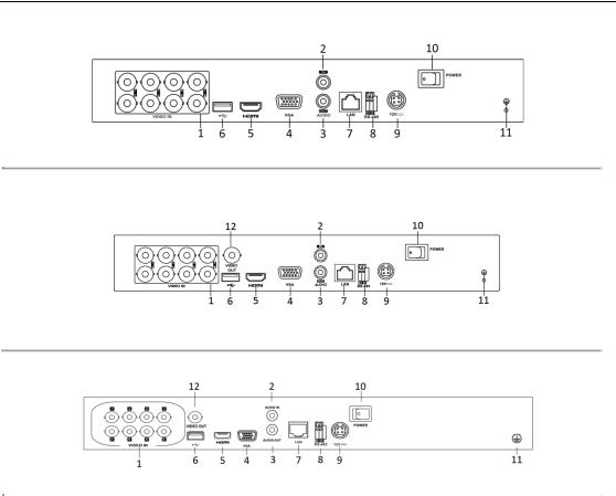
Digital Video Recorder User Manual
Rear Panel 3:
Figure 1. 10 Rear Panel of DS-7200HGHI-E1/E2
Rear Panel 4:
Figure 1. 11 Rear Panel of DS-7200HQHI-F1/N
Rear Panel 5:
|
|
|
|
|
Figure 1. 12 Rear Panel of DS-7200HQHI-F2/N |
||
|
|
|
|
|
|
|
|
|
|
|
|
|
|
Table 1. 11 Description of Rear Panel |
|
|
|
|
|
|
|
|
|
|
|
No. |
|
|
Item |
|
Description |
|
|
1 |
|
|
VIDEO IN |
|
BNC interface for TVI and analog video input. |
|
|
|
|
|
|
|
RCA connector |
|
|
2 |
|
|
AUDIO IN |
|
|
|
|
|
|
AUDIO OUT |
|
RCA connector |
|
|
|
3 |
|
|
|
||
|
|
4 |
|
|
VGA |
|
DB15 connector for VGA output. Display local video output and |
|
|
|
|
|
|||
|
|
|
|
|
menu. |
||
|
|
|
|
|
|
|
|
|
|
|
|
HDMI |
|
HDMI video output connector. |
|
|
|
5 |
|
|
|
||
|
|
6 |
|
|
USB Port |
|
Universal Serial Bus (USB) port for additional devices. |
|
|
|
|
Network Interface |
|
Connector for network |
|
|
|
7 |
|
|
|
||
|
|
8 |
|
|
RS-485 Interface |
|
Connector for RS-485 devices. |
|
|
9 |
|
|
Power Supply |
|
12VDC power supply. |
|
|
10 |
|
|
Power Switch |
|
Switch for turning on/off the device. |
|
|
11 |
|
|
GND |
|
Ground |
|
|
12 |
|
|
VIDEO OUT |
|
BNC connector for video output. |
|
|
|
|
|
|
|
|
|
|
13 |
|
|
ALARM |
|
Connector for alarm input/output. |
|
|
|
|
|
|
|
|
25
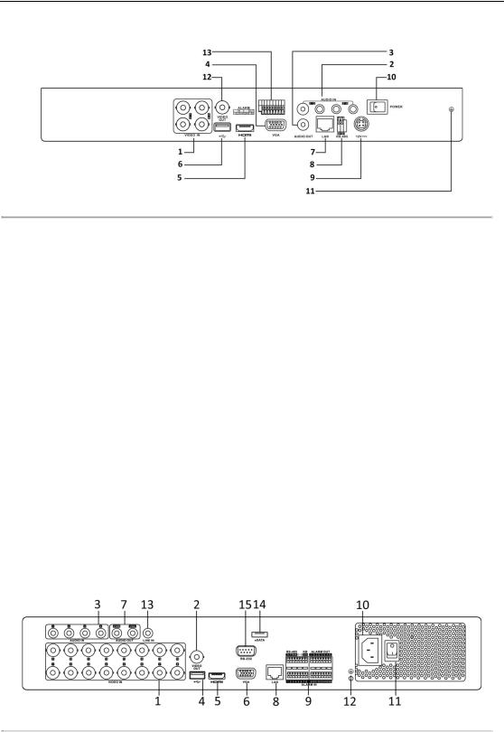
Digital Video Recorder User Manual
Rear Panel 6:
Figure 1. 13 Rear Panel of DS-7200HUHI-F/N
 The rear panels of DS-7208HUHI-F1/N and DS-7208HUHI-F2/N provide 8 video input interfaces. The rear panel of DS-7216HUHI-F2/N provides 16 video input interfaces.
|
|
|
|
|
Table 1. 12 Description of Rear Panel |
|
|
|
|
|
|
|
|
|
No. |
|
|
Item |
|
Description |
|
1 |
|
|
VIDEO IN |
|
BNC interface for TVI and analog video input. |
|
2 |
|
|
AUDIO IN |
|
RCA connector |
|
3 |
|
|
AUDIO OUT |
|
RCA connector. |
|
4 |
|
|
VGA |
|
DB15 connector for VGA output. Display local video output and |
|
|
|
|
|
menu. |
|
|
|
|
|
|
|
|
|
5 |
|
|
HDMI |
|
HDMI video output connector. |
|
6 |
|
|
USB Port |
|
Universal Serial Bus (USB) port for additional devices. |
|
7 |
|
|
Network Interface |
|
Connector for network |
|
8 |
|
|
RS-485 Interface |
|
Connector for RS-485 devices. |
|
9 |
|
|
Power Supply |
|
12VDC power supply. |
|
10 |
|
|
Power Switch |
|
Switch for turning on/off the device. |
|
11 |
|
|
GND |
|
Ground |
|
12 |
|
|
VIDEO OUT |
|
BNC connector for video output. |
|
|
|
Alarm In/Out |
|
Connector for alarm input and output. |
|
|
13 |
|
|
|
||
Rear Panel 6:
Figure 1. 14 Rear Panel of DS-7300HQHI-F4/N
 The rear panel of DS-7304HQHI-F4/N and DS-7308HQHI-F4/N provide 4 and 8 video input interfaces respectively.
26
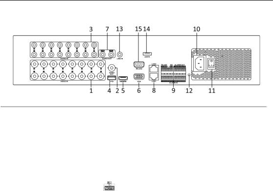
Digital Video Recorder User Manual
Rear Panel 7:
Figure 1. 15 Rear Panel of DS-8100HQHI-F8/N
 The rear panel of DS-8104HQHI-F8/N and DS-8108HQHI-F8/N provide 4 and 8 video input interfaces respectively.
Table 1. 13 Description of Rear Panel
|
No. |
|
|
Item |
|
|
|
Description |
|
1 |
|
|
VIDEO IN |
|
|
|
BNC interface for TVI and analog video input. |
|
|
|
|
VIDEO OUT |
|
|
BNC connector for video output. |
|
|
2 |
|
|
|
|
|
|
CVBS output is not provided by DS-7100/7200HGHI-E1, DS-7200HGHI-E2, |
|
|
|
|
|
|
|
|
DS-7100/7200HGHI-F1, DS-7200HGHI-F2, DS-7100HQHI-F1/N, and |
|
|
|
|
|
|
|
|
DS-7100HGHI-F1/N series DVR. |
|
3 |
|
|
AUDIO IN |
|
|
|
RCA connector |
|
4 |
|
|
USB Port |
|
|
|
Universal Serial Bus (USB) port for additional devices. |
|
5 |
|
|
HDMI |
|
|
|
HDMI video output connector. |
|
6 |
|
|
VGA |
|
|
|
DB15 connector for VGA output. Display local video output and |
|
|
|
|
|
|
|
menu. |
|
|
|
|
|
|
|
|
|
|
|
7 |
|
|
AUDIO OUT |
|
|
RCA connector. |
|
|
8 |
|
|
Network Interface |
|
|
Connector for network |
|
|
|
|
|
|
|
|
|
Connector for RS-485 devices. T+ and T- pins connect to R+ and R- |
|
|
|
|
|
|
|
|
pins of PTZ receiver respectively. |
|
|
|
|
RS-485 |
and |
Alarm |
|
D+, D- pin connects to Ta, Tb pin of controller. For cascading |
|
9 |
|
|
|
devices, the first DVR’s D+, D- pin should be connected with the |
|||
|
|
|
Interface |
|
|
|
||
|
|
|
|
|
|
|
D+, D- pin of the next DVR. |
|
|
|
|
|
|
|
|
|
|
|
|
|
|
|
|
|
|
Connector for alarm input. |
|
|
|
|
|
|
|
|
Connector for alarm output. |
|
10 |
|
|
Power Supply |
|
|
100 to 240V AC power supply. |
|
|
11 |
|
|
Power Switch |
|
|
Switch for turning on/off the device. |
|
|
12 |
|
|
GND |
|
|
|
Ground |
|
13 |
|
|
LINE IN |
|
|
|
BNC connector for audio input. |
|
|
|
|
|
|
|
|
Connects external SATA HDD, CD/DVD-RW. |
|
14 |
|
|
eSATA |
|
|
|
|
|
15 |
|
|
RS-232 Interface |
|
|
Connector for RS-232 devices. |
|
27

Digital Video Recorder User Manual
Chapter 2 Getting Started
28

Digital Video Recorder User Manual
2.1 Starting Up and Shutting Down the DVR
Purpose:
Proper startup and shutdown procedures are crucial to expanding the life of the DVR.
Before you start:
Check that the voltage of the extra power supply is the same with the DVR’s requirement, and the ground connection is working properly.
Starting up the DVR
Steps:
1.Check the power supply is plugged into an electrical outlet. It is HIGHLY recommended that an Uninterruptible Power Supply (UPS) be used in conjunction with the device.
2.Turn on the power switch on the rear panel, and the Power indicator LED should turn on indicating that the unit begins to start up.
3.After startup, the Power indicator LED remains on.
Shutting down the DVR
Steps:
There are two proper ways to shut down the DVR. To shut down the DVR:
OPTION 1: Standard shutdown
1.Enter the Shutdown menu. Menu > Shutdown
Figure 2. 1 Shutdown Menu
2.Select the Shutdown button.
3.Click the Yes button.
4.Turn off the power switch on the rear panel when the note appears.
Figure 2. 2 Shutdown Tips
Rebooting the DVR
While in the Shutdown menu (Figure 2. 1), you can also reboot the DVR.
Steps:
1.Enter the Shutdown menu by clicking Menu > Shutdown.
2.Click the Logout button to log out or the Reboot button to reboot the DVR.
29
Loading...