


SETUP & OPERATION MANUAL
FEATURES
 Large surface, ground cast-iron tables for stability and added support when feeding longer stock.
 Heavy-duty, three-knife cutter head for clean, fast, superior finish cuts.
 Jackscrew system for quick, easy knife adjustment.
 Large, heavy-duty, center-mounted castiron fence with 45°, 90° and 135° positive stops.
 Independent in-feed and out-feed table adjustment hand wheels. Built-in rabbeting ledge.
 4” dust collection port.
 Includes: 2 hand-paddle style push blocks with onboard storage mounts.
 Magnetic safety switch with overload protection.
 Convenient front to back fence adjustment hand wheel.
 Motor mounted on vibro-eliminators for smooth, quiet operation.
SPECIFICATIONS
TABLE SIZE
9 1⁄4’’ x 74 7⁄8’’ (235 x 1900 mm)
IN-FEED TABLE (L X W)
36 1⁄2’’ x 9 1⁄4’’ (936 x 235 mm)
OUT-FEED TABLE (L X W)
36 1⁄2’’ x 9 1⁄4’’ (936 x 235 mm)
MAXIMUM CUTTING WIDTH 8’’ (203 mm)
MINIMUM CUTTING DEPTH 1⁄2’’ (13 mm)
RABBETING CAPACITY 1⁄2’’ (13 mm)
FENCE SIZE
4’’ x 38’’ (102 x 965 mm)
CUTTER HEAD SPEED 5500 RPM
NUMBER OF KNIVES 3 / HELICAL
BASE DIMENSIONS (L X W) 29’’ x 17’’ (736.6 x 431.8 mm)
MOTOR
M1 - 2 HP, 220 V, 1 Ph, 12 A
M2 - 2 HP, 220 V, 3 Ph, 6 A
M3 - 2 HP, 600 V, 3 Ph, 3 A
WEIGHT
572 LBS (260 kg)
8” DELUXE JOINTER
MODEL
#80-200L #80-200LHC
REVISION 1 - JANUARY 28/10
© COPYRIGHT GENERAL INTERNATIONAL 01/2010

GENERAL® INTERNATIONAL
8360 Champ-d’Eau, Montreal (Quebec) Canada H1P 1Y3 Telephone (514) 326-1161 • Fax (514) 326-5555 • www.general.ca
THANK YOU for choosing this General® International model 80-200L or 80-200LHC 8” Deluxe Jointer. This jointer has been carefully tested and inspected before shipment and if properly used and maintained, will provide you with years of reliable service. To ensure optimum performance and trouble-free operation, and to get the most from your investment, please take the time to read this manual before assembling, installing and operating the unit.
The manual’s purpose is to familiarize you with the safe operation, basic function, and features of this jointer as well as the set-up, maintenance and identification of its parts and components. This manual is not intended as a substitute for formal woodworking instruction, nor to offer the user instruction in the craft of woodworking. If you are not sure about the safety of performing a certain operation or procedure, do not proceed until you can confirm, from knowledgeable and qualified sources, that it is safe to do so.
Once you’ve read through these instructions, keep this manual handy for future reference.
Disclaimer: The information and specifications in this manual pertain to the unit as it was supplied from the factory at the time of printing. Because we are committed to making constant improvements, General® International reserves the right to make changes to components, parts or features of this unit as deemed necessary, without prior notice and without obligation to install any such changes on previously delivered units. Reasonable care is taken at the factory to ensure that the specifications and information in this manual corres-
ponds with that of the unit with which it was supplied. However, special orders and “after factory” modifications may render some or all information in this manual inapplicable to your machine. Further, as several generations of this model of jointer and several versions of this manual may be in circulation, if you own an earlier or later version of this unit, this manual may not depict your machine exactly. If you have any doubts or questions contact your retailer or our support line with the model and serial number of your unit for clarification.

GENERAL® & GENERAL® INTERNATIONAL WARRANTY
All component parts of General®, General® International and Excalibur by General International ® products are carefully inspected during all stages of production and each unit is thoroughly inspected upon completion of assembly.
Limited Lifetime Warranty
Because of our commitment to quality and customer satisfaction, General® and General® International agree to repair or replace any part or component which upon examination, proves to be defective in either workmanship or material to the original purchaser for the life of the tool. However, the Limited Lifetime Warranty does not cover any product used for professional or commercial production purposes nor for industrial or educational applications. Such cases are covered by our Standard 2-year Limited Warranty only. The Limited Lifetime Warranty is also subject to the “Conditions and Exceptions” as listed below.
Standard 2-Year Limited Warranty
All products not covered by our lifetime warranty including products used in commercial, industrial and educational applications are warranted for a period of 2 years (24 months) from the date of purchase. General® and General® International agree to repair or replace any part or component which upon examination, proves to be defective in either workmanship or material to the original purchaser during this 2-year warranty period, subject to the “conditions and exceptions” as listed below.
To file a Claim
To file a claim under our Standard 2-year Limited Warranty or under our Limited Lifetime Warranty, all defective parts, components or machinery must be returned freight or postage prepaid to General® International, or to a nearby distributor, repair center or other location designated by General® International. For further details call our service department at 1-888- 949-1161 or your local distributor for assistance when filing your claim.
Along with the return of the product being claimed for warranty, a copy of the original proof of purchase and a “letter of claim” must be included (a warranty claim form can also be used and can be obtained, upon request, from General® International or an authorized distributor) clearly stating the model and serial number of the unit (if applicable) and including an explanation of the complaint or presumed defect in material or workmanship.
CONDITIONS AND EXCEPTIONS:
This coverage is extended to the original purchaser only. Prior warranty registration is not required but documented proof of purchase i.e. a copy of original sales invoice or receipt showing the date and location of the purchase as well as the purchase price paid, must be provided at the time of claim.
Warranty does not include failures, breakage or defects deemed after inspection by General® or General® International to have been directly or indirectly caused by or resulting from; improper use, or lack of or improper maintenance, misuse or abuse, negligence, accidents, damage in handling or transport, or normal wear and tear of any generally considered consumable parts or components.
Repairs made without the written consent of General® Internationallwill void all warranty.

TABLE OF CONTENTS
Rules for safe operation . . . . . . . . . . . . . . .5
Additional Safety Instructions for Jointers . .6
Electrical requirements . . . . . . . . . . . . . . .7
Grounding instructions . . . . . . . . . . . . . . . . . . . . . . .7 Circuit capacity . . . . . . . . . . . . . . . . . . . . . . . . . . . . .7 Extension cords . . . . . . . . . . . . . . . . . . . . . . . . . . . . .7
Basic functions . . . . . . . . . . . . . . . . . . . . .8
Identification of main parts and components .8
Unpacking . . . . . . . . . . . . . . . . . . . . . . . . .9
Preparation and placement within the shop 10
Additional requirements for set up . . . . . . . . . . . .10 Clean up . . . . . . . . . . . . . . . . . . . . . . . . . . . . . . . . . .10 Placement within the shop . . . . . . . . . . . . . . . . . . .10 Establishing a safety zone . . . . . . . . . . . . . . . . . . .10
Assembly instructions . . . . . . . . .11-16
Attach the jointer bed to the base . . . . . . . . . . . .11 Install the V-belts . . . . . . . . . . . . . . . . . . . . . . . . . . . .12 Pulley parallel alignment . . . . . . . . . . . . . . . . . . . .12 Verify belt tension . . . . . . . . . . . . . . . . . . . . . . . . . .12 Install the cutter head guard . . . . . . . . . . . . . . . . .12 Attach the switch box / connect to the motor . .13
Install the fence and table height adjustment handwheels . . . . . . . . . . . . . . . . . . . . . . . . . . . . . . .14
Install the dust port . . . . . . . . . . . . . . . . . . . . . . . . .14 Install the base door . . . . . . . . . . . . . . . . . . . . . . . .14 Re-position the fence locking handle . . . . . . . . .15 Install the fence tilt lever . . . . . . . . . . . . . . . . . . . . .15 Assemble the knife setting gauge . . . . . . . . . . . . .15
Connecting to a dust collector . . . . . . . . . . . . . . .16
Adjusting and setting the out-feed
table height . . . . . . . . . . . . . . . . . . . . . . .16
Adjusting and setting the in-feed table height / depth of cut . . . . . . . . . . . . . . . . .16
Checking / adjusting the depth of cut indicator . . . . . . . . . . . . . . . . . . . . . . . . .17
Adjusting the fence & checking /setting the fence stops . . . . . . . . . . . . . . . . . . . . . . .17
Checking knives - model 80-200LHC only . . . . . . .18
Operating instructions . . . . . . . . .19-22
Basic principles of jointing . . . . . . . . . . . . . . . . . . .19 Selecting boards suitable for jointing . . . . . . . . . .19
Determine the concave face and edge of your board . . . . . . . . . . . . . . . . . . . . . . . . . . . . . . . . . . . .20
Adjust fence front to back position . . . . . . . . . . . .20 Checklist before starting . . . . . . . . . . . . . . . . . . . . .20 Connecting to a power source . . . . . . . . . . . . . . .21 Magnetic safety switch . . . . . . . . . . . . . . . . . . . . . .21 Overload protection . . . . . . . . . . . . . . . . . . . . . . . .21
Basic jointing operations . . . . . . . . . . . . . |
22 |
Surface planing . . . . . . . . . . . . . . . . . . . . . . . . . . . .22 Edge jointing . . . . . . . . . . . . . . . . . . . . . . . . . . . . . .22 Rabbeting . . . . . . . . . . . . . . . . . . . . . . . . . . . . . . . . .22
Maintenance . . . . . . . . . . . . . . . . . .23-26
Inspecting/replacing cutter head knives . . . . . .23
Knife setting or replacement
- model 80-200L only . . . . . . . . . . . . . . . . . . . . . . . . . . . .24
Helical cutter head insert reversal/
replacement - model 80-200LHC only . . . . . . . . . . . . .25 Adjusting the gibs . . . . . . . . . . . . . . . . . . . . . . . . . .26 Periodic maintenance . . . . . . . . . . . . . . . . . . . . . .26
Recommended optional accessories . . . . .27
Wiring Diagram . . . . . . . . . . . . . . . . . . . .28
Parts list & diagrams . . . . . . . . . . . . . .28-32
Contact information . . . . . . . . . . . . . . . . .34

RULES FOR SAFE OPERATION
To help ensure safe operation, please take a moment to learn the machine’s applications and limitations, as well as potential hazards. General® International disclaims any real or implied warranty and holds itself harmless for any injury that may result from improper use of its equipment.
1.Do not operate this jointer when tired, distracted, or under the effects of drugs, alcohol or any medication that impairs reflexes or alertness.
2.The working area should be well lit, clean and free of debris.
3.Keep children and visitors at a safe distance when the jointer is in operation; do not permit them to operate the jointer.
4.Childproof and tamper proof your shop and all machinery with locks, master electrical switches and switch keys, to prevent unauthorized or unsupervised use.
5.Stay alert! Give your work your undivided attention. Even a momentary distraction can lead to serious injury.
6.Fine particulate dust is a carcinogen that can be hazardous to health. Work in a well-ventilated area and whenever possible use a dust collector. Wear face, eye, ear, respiratory and body protection devices.
7.Do not wear loose clothing, gloves, bracelets, necklaces or other jewelry while the jointer is in operation. Wear protective hair covering to contain long hair and wear non-slip footwear.
8.Be sure that adjusting wrenches, tools, drinks and other clutter are removed from the machine and/or the table surface before operating.
9.Keep hands well away from knives and all moving parts. Use a push stick to feed stock, and a brush, not hands, to clear away chips and dust.
10.Be sure that the knives are securely installed in the cutterhead.
11.Always use clean, properly sharpened knives. Dirty or dull knives are unsafe and can lead to accidents.
12.If using a power feeder, stop the feeder before stopping the jointer.
13.Do not push or force stock into the cutter head. The jointer will perform better and more safely when working at the rate for which it was designed.
14.Be sure that the cutter head has gained full operating speed before starting to joint.
15.Avoid working from awkward or off balance positions. Do not overreach and keep both feet on floor.
16.Keep guards in place and in working order. If a guard must be removed for maintenance or cleaning be sure it is properly re-attached before using the tool again.
17.Use of parts and accessories NOT recommended by GENERAL→ INTERNATIONAL may result in equipment malfunction or risk of injury.
18.Never stand on machinery. Serious injury could result if the tool is tipped over or if the cutting tool is unintentionally contacted.
19.Always disconnect the tool from the power source before servicing or changing accessories such as knives, or before performing any maintenance or cleaning, or if the machine will be left unattended.
20.Make sure that the switch is in the “OFF” position before plugging in the power cord.
21.Make sure the tool is properly grounded. If equipped with a 3-prong plug it should be used with a three-pole receptacle. Never remove the third prong.
22.Do not use this jointer for other than its intended use. If used for other purposes, GENERAL→ INTERNATIONAL disclaims any real implied warranty and holds itself harmless for any injury, which may result from that use.
5

Additional Safety
Instructions for Jointers
Because each shop situation is unique, no list of safety guidelines can ever be complete.
The most important safety feature of any shop is the knowledge and good judgement of the user. Use common sense and always keep safety considerations, as they apply to your individual shop conditions, first and foremost in mind. If you have any doubts about the safety of an operation you are about to perform: STOP! Do not perform the operation until you have validated from qualified individuals if the operation is safe to perform and what is the safest method to perform it.
1. WORK PIECE KICKBACK
Kickback is when the work piece is ejected at high speeds from the jointer table by the force of the cutter head. To minimize the risk of injury from kickback, always use push blocks and wear safety glasses. Do not operate this machine if you do not understand kickback, its causes and how to avoid it.
2. CUTTER HEAD ALIGNMENT
To reduce the risk of injury and to avoid kickback, keep the top edge of the outfeed table aligned with the top dead center edge of the knife.
3. PUSH BLOCKS
Always use push blocks when jointing. Never pass your bare hands directly over the cutter head without a push block to hold and guide the workpiece.
4. WORKPIECE SUPPORT
To make safe cuts and reduce the risk of injury, support the workpiece adequately at all times. Never attempt to make a cut with an unstable workpiece.
5. KICKBACK ZONE
The kickback zone on a jointer is the area directly in the path through and off of the end of the infeed table. Never stand or allow others to stand in this area during operation.
6. MAXIMUM DEPTH OF CUT
The maximum depth of cut for one pass is 1/8”. Never attempt to remove more material than 1/8” in any single pass.
7. JOINTING WITH THE GRAIN
Jointing against the grain or jointing end grain is dangerous and could produce chatter or excessive chip out. Always joint with the grain.
8. KEEPING GUARDS IN PLACE
Except when rabbeting, all operations must be performed with the guard in place. After rabbeting, be sure to replace the guard.
9. PROPER CUTTING
Always move the work piece over the cutter head from the infeed table towards the outfeed table until the work piece has passed completely over the cutter head. Never back the work piece towards the infeed table.
10. USING GOOD WORK PIECE STOCK
Jointing safety begins with the stock used with the machine. Inspect the work piece carefully before jointing it. Never joint a board that has loose knots, staples, nails or other embedded foreign objects. If you have the slightest doubt about the structural integrity or stability of a board: Do Not Joint It.
6
ELECTRICAL REQUIREMENTS
BEFORE CONNECTING THE MACHINE TO THE POWER SOURCE, VERIFY THAT THE VOLTAGE OF YOUR POWER SUPPLY CORRESPONDS WITH THE VOLTAGE SPECIFIED ON THE MOTOR I.D. NAMEPLATE. A POWER SOURCE WITH GREATER VOLTAGE THAN NEEDED CAN RESULT IN SERIOUS INJURY TO THE USER AS WELL AS DAMAGE TO THE MACHINE. IF IN DOUBT, CONTACT A QUALIFIED ELECTRICIAN BEFORE CONNECTING TO THE POWER SOURCE.
THIS TOOL IS FOR INDOOR USE ONLY. DO NOT EXPOSE TO RAIN OR USE IN WET OR DAMP LOCATIONS.
VOLTAGE REQUIREMENTS AND AMPERAGE DRAW FOR M2 & M3 3-PHASE MOTORS MAY NOT BE FULLY DESCRIBED IN THIS MANUAL. FOR COMPLETE ELECTRICAL REQUIREMENTS REFER TO THE MOTOR I.D. NAME PLATE ON THE MACHINE. IF IN DOUBT CONSULT A LICENSED QUALIFIED ELECTRICIAN BEFORE PROCEEDING.
A C
B
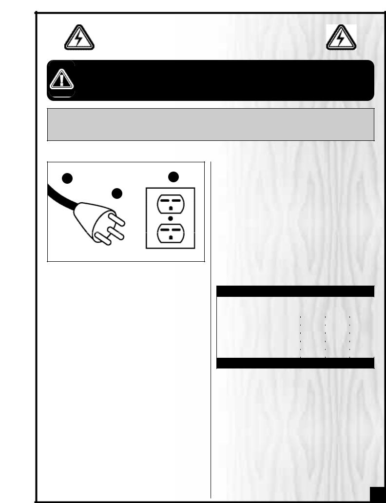
GROUNDING INSTRUCTIONS
In the event of an electrical malfunction or short circuit, grounding reduces the risk of electric shock to the operator. The motor of this machine is wired for 220V single phase operation and is equipped with a 3-conductor cord A and a 3-prong grounded plug B to fit a matching grounding type receptacle C.
DO NOT MODIFY THE PLUG PROVIDED ! If it will not fit your receptacle, have the proper receptacle installed by a qualified electrician.
CHECK with a qualified electrician or service person if you do not completely understand these grounding instructions, or if you are not sure the tool is properly grounded.
CIRCUIT CAPACITY
Make sure that the wires in your circuit are capable of handling the amperage draw from your machine, as well as any other machines that could be operating on the same circuit. If you are unsure, consult a qualified electrician. If the circuit breaker trips or the fuse blows regularly, your machine may be operating on a circuit that is close to its amperage draw capacity. However, if an unusual amperage draw does not exist and a power failure still occurs, contact a qualified technician or our service department.
EXTENSION CORDS
The use of an extension cord is not generally recommended for 220V equipment. If you find it necessary, use only 3-wire extension cords that have 3-prong grounding plug and a matching 3-pole receptacle that accepts the tool’s plug. Repair or replace a damaged extension cord or plug immediately.
If you find it necessary to use an extension cord with your machine make sure the cord rating is suitable for the amperage listed on the motor I.D. plate. An undersized cord will cause a drop in line voltage resulting in loss of power and overheating. The accompanying chart shows the correct size extension cord to be used based on cord length and motor I.D. plate amp rating. If in doubt, use the next heavier gauge. The smaller the number, the heavier the gauge.
TABLE - MINIMUM GAUGE FOR CORD
AMPERE |
|
TOTAL LENGTH OF CORD IN FEET |
|
||
220 VOLTS |
50 FEET |
100 FEET |
200 FEET |
300 FEET |
|
RATING |
|
|
|
|
|
|
|
|
AWG |
|
|
< 5 |
-------> |
18 |
16 |
16 |
14 |
6 TO 10 |
-------> |
18 |
16 |
14 |
12 |
10 TO 12 |
-------> |
16 |
16 |
14 |
12 |
12 TO 16 |
-------> |
14 |
12 |
* NR |
* NR |
* NR = Not Recommended
7

8” DELUXE JOINTER
80-200L & 80-200LHC
BASIC FUNCTIONS
This 8” jointer is designed for face and edge jointing in solid wood only. The unit is not designed nor should it be used to surface or prepare, plywood, wood panelling, particleboard, MDF nor any other wood based by-products nor any non-wood based materials.
This 8” jointer is offered with 2 different cutter head options as follows:
•Model 80-200L M1 – 8” jointer with standard 3-knife cutter head;
•Model 80-200LHC M1 - 8” jointer with “Byrd” style helical cutter head with reversible four-sided carbide inserts.
IDENTIFICATION OF MAIN PARTS AND COMPONENTS
OUTFEED TABLE |
RABBETING ARM |
CUTTER HEAD GUARD |
FENCE ASSEMBLY |
|
|
|
INFEED TABLE |
OUT-FEED TABLE |
|
|
|
ADJUSTMENT |
|
|
|
HANDWHEEL |
|
|
DEPTH OF CUT |
|
|
|
|
|
|
|
INDICATOR |
|
|
|
IN-FEED TABLE ADJUSTMENT |
|
|
|
HANDWHEEL |
TABLE LOCKING LEVERS |
|
PUSH BLOCKS |
|
|
|
||
|
|
|
MAGNETIC SWITCH |
|
|
|
BASE WITH MOTOR |
REAR VIEW
90º FENCE STOP BOLT
FENCE TILT LEVER
TABLE DEPTH |
|
|
|
FENCE LOCK LEVER |
ADJUSTMENT |
|
|
|
|
|
|
|
(TILT) |
|
LOCK PIN |
|
|
|
|
|
|
|
|
|
FENCE ADJUSTMENT |
|
|
FENCE LOCK LEVER |
|
|
|
|||
|
|
|
(MOVING) |
|
HANDWHEEL |
|
|
|
|
|
|
|
|
|
8

UNPACKING 80- 80-200LHC
Carefully unpack and remove the unit and its components from its shipping crate and check for missing or damaged items as per the list of contents below.
NOTE: Please report any damaged or missing items to your GENERAL® INTERNATIONAL distributor immediately.
LIST OF CONTENTS |
QTY |
|||
A |
|
|
|
|
- |
JOINTER ASSEMBLY W/FENCE.......................................... |
1 |
||
B |
- |
CUTTER HEAD GUARD....................................................... |
1 |
|
C |
- |
DUST PORT......................................................................... |
1 |
|
D |
- |
4” HAND WHEEL ................................................................ |
1 |
|
E |
- |
6” HAND WHEEL ................................................................ |
2 |
|
F |
- |
FENCE TILT LEVER .............................................................. |
1 |
|
G* - |
BASE................................................................................... |
1 |
||
H |
- |
MAGNETIC SAFETY SWITCH.............................................. |
1 |
|
I |
- |
V-BELT................................................................................. |
2 |
|
J** - |
KNIFE SETTING GAUGE |
|
|
|
|
|
Knife setting gauge rod ................................................. |
1 |
|
|
|
Knife setting gauge foot ................................................ |
2 |
|
|
|
E-clip ................................................................................. |
4 |
|
K |
- |
PUSH BLOCK ..................................................................... |
2 |
|
L - |
|
BASE DOOR....................................................................... |
1 |
|
M |
- |
MOUNTING BOLT .............................................................. |
3 |
|
N |
- |
LOCK WASHER .................................................................. |
3 |
|
O |
- FLAT WASHER..................................................................... |
4 |
P |
- PHILLIPS HEAD SCREW...................................................... |
4 |
Q |
- TOOLS |
|
|
8-10 mm open end wrench........................................... |
1 |
|
12-14 mm open end wrench......................................... |
1 |
|
17-19 mm open end wrench......................................... |
1 |
|
3 mm Allen key................................................................ |
1 |
|
4 mm Allen key................................................................ |
1 |
|
5 mm Allen key................................................................ |
1 |
R*** - HELICAL CUTTER HEAD TOOLS/REPLACEMENT |
|
|
|
Screw .............................................................................. |
10 |
|
Carbide insert ................................................................. |
5 |
|
Star point screw driver .................................................... |
2 |
* The safety switch is not already installed on the
**Not included or required on “HC” model.
***Included on “HC” model only.
G*
D E
C
F
B
J **
I
R ***
Q
N

9
PREPARATION AND PLACEMENT WITHIN THE SHOP
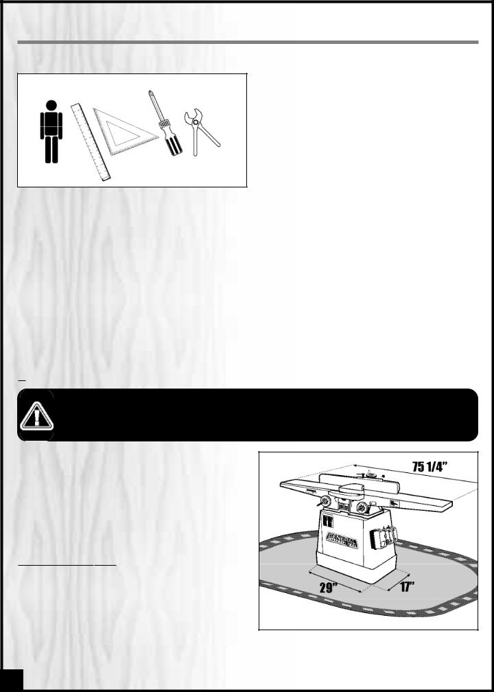
ADDITIONAL REQUIREMENTS FOR SET UP
• 3 Extra people to assist with lifting
• Straightedge
• 45º & 90º combination square
• Phillips Screwdriver
• Pliers or Vise-grips
X3
CLEAN UP
The protective coating on the jointer tables prevents rust from forming during shipping and storage. Remove it by rubbing with a rag dipped in kerosene, mineral spirits or paint thinner. (Dispose of potentially flammable solventsoaked rags according to manufacturer’s safety recommendations.)
A putty knife, held flat to avoid scratching the surface, may also be used to scrape off the coating followed by clean-up with solvent. Avoid rubbing the saw’s painted surfaces, as many solvent-based products will remove paint.
To prevent rust, apply a light coating of paste wax or use regular applications of any after-market surface protectant or rust inhibitor.
PLACEMENT WITHIN THE SHOP
THIS MODEL 80-200L/LHC JOINTER IS HEAVY – 572 LBS (260 KG). DO NOT OVER-EXERT. THE HELP OF OF AT LEAST THREE ASSISTANTS, A HOIST OR FORKLIFT WILL BE NEEDED FOR THE FOLLOWING STEP.
TO LIMIT THE RISK OF SERIOUS INJURY OR DAMAGE TO THE MACHINE, ANY EQUIPMENT USED TO LIFT THIS MACHINE (HOIST OR FORKLIFT) SHOULD HAVE A RATED CAPACITY IN EXCESS OF 572 LBS - 260 KG.
10

ASSEMBLY INSTRUCTIONS
SERIOUS PERSONAL INJURY COULD OCCUR IF YOU CONNECT |
MACHINE TO THE POWER |
BEFORE YOU HAVE COMPLE- |
TED THE INSTALLATION AND ASSEMBLY STEPS. DO NOT |
MACHINE TO THE POWER |
UNTIL INSTRUCTED TO DO |
SO. |
|
|
ATTACH THE JOINTER BED TO THE BASE
C
THE JOINTER BED IS VERY HEAVY. DO NOT OVER-EXERT. THE HELP OF AT LEAST THREE ASSISTANTS WILL BE NEEDED FOR THE FOLLOWING STEP.
1.Using a hoist or with the help of three assistants, carefully lift the jointer bed onto the base A.
|
|
|
|
|
|
|
|
|
|
|
|
|
|
|
|
|
|
|
|
|
|
|
|
the 3 bolt holes on |
jointer bed with |
||||
|
|
|
|
on the base. |
|
||||
|
|
|
|
the supplied |
bolts with lock washers |
||||
|
|
|
to bolt the jointer to |
base through |
|||||
|
|
|
|
|
|
|
|
holes from |
the cabinet |
|
|
|
|
the bottom of the |
bed C. |
||||
Note: Only hand-tighten the for now. Final tightening done after pulley alignment.
INSTALL THE V-BELTS
C |
D |
B
1. Loosen and |
knob A, then remove the |
upper pulley |
B to give yourself unimpeded |
access to the |
pulley C. |
PULL |
- DO NOT USE SHARP TUGS! KEEP YOUR |
LOWER |
FAR ENOUGH ABOVE THE MOTOR PULLEY |
TO AVOID |
HAND BETWEEN THE BELT AND THE |
PULLEY. |
|
3.Using both hands, carefully pull down on the belt to rotate the pulleys and allow the belt to seat itself
in the groove, |
shown in E. |
4. Repeat step |
install the second belt F. |
Place a V-belt on the |
groove on the upper |
|
||||
pulley D, then fit and |
portion of the oppo- |
|
||||
|
|
|
|
|
|
|
site end of the belt into |
corresponding groove |
|
||||
on the motor pulley. |
|
|
|
|
||
|
|
|
|
|
|
|
|
|
|
|
|
|
|
|
|
|
|
|
|
|
11
 Loading...