


350RNK
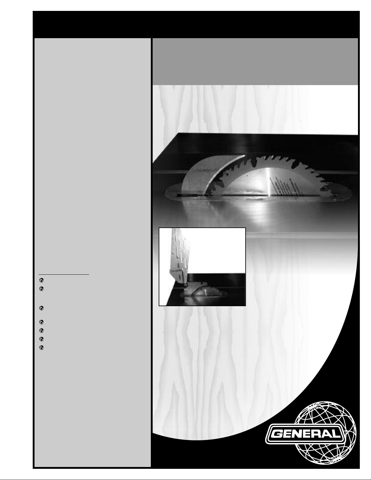
SETUP & OPERATION MANUAL
RIVING KNIFE CONVERSION /
RETROFIT KIT
For General MFG model 350 right-tilt saw.
Kit contains all parts and components to retrofit /convert a non-riving knife model 350, 3HP*
saw to the new type 350R saw with riving style
(raises and lowers with the blade) splitter /
blade guard assembly with anti-kickback
pawls and a European style “true” riving knife
- both included with kit.
*Note for 5 HP motors, modifications to the
motor shaft will be required - contact our
technical service or your local distributor for
details.
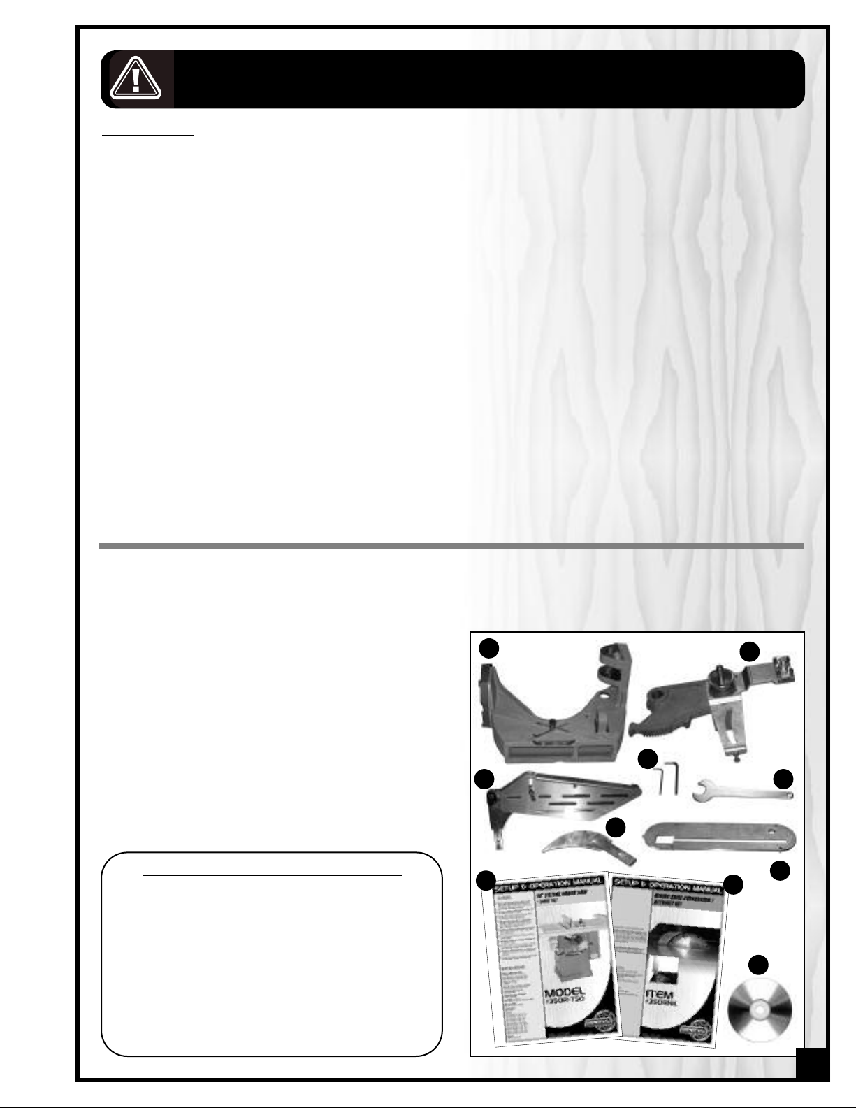
350RNK KIT INCLUDES:
New cast-iron saw chute assembly.
New arbor bracket assembly (with arbor)
with built-in riving knife mounting
block/receptacle.
New riving style splitter/blade guard
assembly.
Riving knife
New table insert
Retro-fit instructional DVD
New & improved saw manual for new
350R saw.
ITEM
#350RNK
REVISION 1 - March 29/09
ight General®MFG / General® Inter
yr
© Cop
national 03/2009

GENERAL® MFG (CO) LTD.
835, Cherrier Street, Drummondville (Quebec) Canada J2B 5A8
Telephone (514) 326-1161 • Fax (514) 326-5555 • www.general.ca
THANK YOU for choosing this General
®
MFG model 350RNK Riving knife conversion / Retrofit kit. This Retrofit kit has been carefully tested and inspected before shipment
and if properly installed, will provide you with years of reliable service. To ensure optimum performance and trouble-free operation, and to get the most from your investment, please take
the time to read this manual before assembling, installing and operating the unit.
The manual’
s purpose is to familiarize you with the safe operation, basic function, and features
of this retrofit kit as well as the set-up, maintenance and identification of its parts and compo-
ormal w
. This man
nents
fer the user instruction in the craft of woodworking. If you are not sure about the safety of
of
orming a certain operation or procedure, do not proceed until you can confirm, from
perf
ual is not intended as a substitute f
or f
oodworking instruction, nor to
knowledgeable and qualified sources, that it is safe to do so.
Once you’ve read through these instructions, keep this manual handy for future reference.
Disclaimer: The information and specifications in this
manual pertain to the unit as it was supplied from the
actory at the time of printing. Because we are commit-
f
ted to making constant improvements, General
ves the right to make changes to
ble car
eser
e is tak
en a
t the f
y to ensure that
actor
tional r
na
Inter
components, parts or features of this unit as deemed
necessary,without prior notice and without obligation to
install any such changes on previously delivered units.
Reasona
the specifications and information in this manual corres-
ponds with that of the unit with which it was supplied.
However, special orders and “after factory” modifications may r
®
inapplicable to your machine. Further, as several gene-
tions of this model and se
ra
may be in circulation, if you own an earlier or later version of this unit, this manual may not depict your tool
exactly. If you have any doubts or questions contact
our r
y
of your unit for clarification.
ender some or all information in this manual
ersions of this manual
eral v
v
etailer or our suppor
t line with the model n
umber
RULES FOR SAFE OPERATION
To help ensure safe operation, please take a moment to learn the machine’s applications and limitations, as well as poten-
ial hazards. General® MFG disclaims any real or implied warranty and holds itself harmless for any injury that may result
t
from improper use of its equipment.
o not operate the saw when tired, distracted, or
1.D
under the effects of drugs, alcohol or any medication that impairs reflexes or alertness.
he working area should be well lit, clean and free
2.T
of debris.
3. Keep children and visitors at a safe distance when
the saw is in operation; do not permit them to
operate the saw.
4. Childproof and tamper proof your shop and all
machiner
and switch keys, to prevent unauthorized or unsupervised use.
5. Stay alert! Give your work your undivided atten
tion. Even a momentary distraction can lead to serious injury.
6. Fine particulate dust is a carcinogen that can be
hazardous to health. Work in a well-ventilated area
and whenever possible use a dust collector and
wear eye, ear and respiratory protection devices.
7. Do not wear loose clothing, gloves, bracelets, necklaces or other jewelry while the saw is in operation.
Wear protective hair covering to contain long hair
and wear non-slip footwear.
8. Be sure that adjusting wrenches, tools, drinks and
other clutter are removed from the machine and/or
the feed table surface before operating.
9. Keep hands well away from the blade and all moving parts. Use a brush, not hands, to clear away
chips and dus
10. Be sure that the blade is securely installed and in
proper cutting direction before operation.
11. Be sure the blade has gained full operating speed
before beginning to cut.
w
12. Al
Dirty or dull blades are unsafe and can lead to
accidents.
13. If using a power feeder,stop the feeder before stopping the ta
y with locks, master electrical switches
t.
ly sharpened blade.
ays use a clean,
ble saw.
proper
se suitable support when cutting stock that does
15.U
not have a flat surface. Always hold stock firmly
against the fence when ripping, or against the miter
gauge when cross-cutting.
16. To minimize risk of injury in the event of workpiece
kickback, never stand directly in-line with the blade
or in the potential kickback path of the work piece.
17. Avoid working from awkward or off balance positions. Do not overreach while cutting; keep both
feet on floor. Never lean over or reach over the
blade and never pull the work piece over the blade
from behind. Use out feed support or have an assistant help when ripping long material.
18. Keep blade guards in place and in working order.
If a guard must be removed for maintenance or
cleaning, be sure it is properly reattached before
using the tool again.
19. Never leave the machine running with the power
on when not in operation.
20. Use of parts and accessories NOT recommended
by
GENERAL MFG
function or risk of injury.
21. Never stand on machinery. Serious injury could
result if the tool is tipped over or if the blade is unintentionally contacted.
22. Always disconnect tool from power before servicing
or changing accessories such as blades, or before
orming an
perf
ments, or if the machine will be left unattended.
e that switch is in "OFF" position bef
23. Mak
24. Make sure the tool is properly grounded. If equip-
25. Do not use this saw for other than its intended use. If
e sur
plugging in the power cord.
ped with a 3-prong plug it should be used with a
ee-pole receptacle. Never remove the third
thr
prong.
used for other purposes,
any real implied warranty and holds itself harmless
or any injury, which may result from that use.
f
may result in equipment mal-
y maintenance,
cleaning or adjust-
GENERAL MFG
ore
disclaims
14. Do not push or force stock into the blade. The saw
will perform better and more safely when working
at the rate for which it was designed.
3

RIVING KNIFE CONVERSION / RETROFIT KIT
350RNK
BASIC FUNCTIONS
The parts and components supplied in this 350RNK riving knife retro-fit / conversion kit have been designed to fit on
General MFG 3HP* right tilt model 350** saw only.
a
*For 5 HP motors, modifications to the motor shaft will be required - contact our technical service or your local distributor for details
before attempting this conversion.
** If you have a model 650 left-tilt saw, you will require retro-fit kit model #650RNK. This kit cannot be fitted to a model 650 left-tilt
saw!
HIS KIT HAS NOT BEEN DESIGNED NOR TESTED TO FIT ON ANY SAW MODEL OTHER THAN AS SPECIFIED IN THIS MANUAL. ANY
T
TTEMPTS TO FIT OR USE THESE PARTS AND COMPONENTS ON ANY SAW OTHER THAN THE MODEL INTENDED, MAY LEAD TO
A
SERIOUS PERSONAL INJURY, DAMAGE TO YOUR SAW AND/OR TO THE PARTS AND COMPONENTS OF THIS KIT.
A word about riving knives:
Upon completion of your saw conversion using this kit, your saw will be equipped with the latest feature available
for North American table saws: A quick connect/ quick release riving knife style of splitter.
A riving knife is considered a newer design for North American saws which traditionally have been equipped with
various fixed height splitter assemblies which perform a similar function. The riving knife has proven effective and
has been in use on saws in Europe for many years and is becoming a required table saw safety accessory for new
saws throughout most of North America.
The riving knife sits behind the blade to help prevent a workpiece, as it is pushed through the cut, from closing back
and “pinching” the blade or from drifting away from the rip fence and catching the rear portion of the saw blade.
Such situations can lead to what is commonly referred to as a kickback, where by the shear force of the saws motor
and with the forward rotation of the blade, the workpiece is lifted and violently ejected towards the front of the saw.
A kickback can cause serious injury to the user or to anyone within its path.
A traditional splitter does not raise or lower with the blade – it stays at a fixed height at all times, meaning that when
the blade is lowered, the distance between the splitter and the back of the blade increases. The generally accepted theory is that more space between the splitter and the back of the blade does slightly increase the possibility
that the w
saw.
The riving knife however is designed into the blade height adjustment mechanism and not only will it tilt with the
blade but also raise or lower as the blade is raised or lowered, thus keeping it at the exact same distance, usually
some
considered to be a more effective means of helping to prevent kickback caused by the workpiece pinching or
tching on the back of blade.
ca
Like a traditional splitter/blade guard assembly, a riving knife can also be part of an assembly that includes a
blade guar
splitter/guard assembly, because unlike a traditional splitter/blade guard assembly it does still raise and lower with
the blade.
orkpiece could pinch or catch on the back end of the blade and then be thrown towards the front of the
where between 1/4” – 3/8” from the back of the blade at all times. Because of this, a riving knife is generally
d and anti-kickback pawls. This type of an assembly is commonly referred to as a “riving style”
It is important to note however, that though generally considered more effective at preventing kickback from workpiece pinching or ca
to the user against accidental contact with the blade. In such cases a stand alone or independently mounted
blade guar
d/co
tching on the blade, because there is no blade guard, a true riving knife offers no protection
ver is required.
4
ARNING! TO REDUCE THE RISK OF SERIOUS INJURY FROM CONTACT WITH THE BLADE, THE RIVING KNIFE MUST ALWAYS BE
W
SED WITH A BLADE GUARD IN PLACE TO COVER THE BLADE. IF YOU DO NOT OWN AN INDEPENDENTLY ATTACHED BLADE
U
GUARD, THEN USE THE SUPPLIED RIVING STYLE SPLITTER/BLADE GUARD ASSEMBLY FOR ALL OPERATIONS THAT LEAVE THE
BLADE EXPOSED.
Before Starting:
To obtain a good understanding of what will be required, start by watching the DVD video which shows the major
steps and includes some helpful tips and tricks.
After watching the DVD video, read this entire manual and make sure you have all the tools and equipment
required to complete this conversion before starting.
The conversion of an older saw to the new style riving knife design involves heavy lifting, as well as partial disassembly and then re-assembly of some of the major internal components of your saw. Upon completion of re-assembly,
e-alignment of the saws table in relation to the blade is also required. If you are not equipped for or comfortable
r
with this type of mechanical work or if you have any doubt that the required lifting, disassembly, re-assembly or realignment steps are beyond your abilities or skill level:
Stop immediately and proceed no further. Return this kit
and all components in its original packaging to the place of purchase for refund, or contact your local
General/General International distributor to inquire if any on-staff technicians are available and to obtain a quote
to have this kit installed by a trained technician.
Special note regarding images in this manual: The model 350 right tilt saw is basically a mirror image version of the
650 left tilt saw that is depicted in this manual and on the included DVD. Though the images in this manual, and on
the included DVD, show installation on a left tilt saw, for installation on your right tilt model 350, all steps and procedures are the same.
UNPACKING
Carefully unpack and remove the components from the box and check for damaged or missing items as per the
list of contents below.
NOTE: Please report any damaged or missing items to your General® International distributor immediately.
LIST OF CONTENTS QTY
A - CHUTE . . . . . . . . . . . . . . . . . . . . . . . . . . . . . . . . . . . . . .1
B - ARBOR BRACKET . . . . . . . . . . . . . . . . . . . . . . . . . . . . . .1
C - SPLITTER /BLADE GUARD ASSEMBLY . . . . . . . . . . . . . .1
D - 3/32" ALLEN KEY . . . . . . . . . . . . . . . . . . . . . . . . . . . . . .1
5/32"
ALLEN KEY . . . . . . . . . . . . . . . . . . . . . . . . . . . . . .1
E - ARBOR WRENCH . . . . . . . . . . . . . . . . . . . . . . . . . . . . .1
F - EUROPEAN STYLE RIVING KNIFE . . . . . . . . . . . . . . . . .1
G - T
ABLE INSERT . . . . . . . . . . . . . . . . . . . . . . . . . . . . . . . . .1
H - OPERATION MANUAL FOR 350R SAW . . . . . . . . . . . . .1
I - OPERA
TION MANUAL FOR 350RNK
. . . . . . . . . . . . . . .
J - DVD . . . . . . . . . . . . . . . . . . . . . . . . . . . . . . . . . . . . . . . .1
TOOLS REQUIRED TO COMPLETE THIS CONVERSION:
• Socket kit
y set
e
Allen k
•
• 2 large flat head screw
drivers
Rubber mallet
•
Hammer
•
• 3/16” punch or metal
marking awl
• Brass knock-out bar or
long hardwood dowel
General pur
•
machine gr
• Machinists square
Dial indica
•
alignment)
Another per
•
with lifting
pose
ease
or ta
tor/ (f
son for help
ble
1
A
D
C
F
H
B
E
G
I
J
5
PREPARATION BEFORE STARTING
45
3
5
4
0
0
5
1
0
1. Turn off and disconnect the saw from the power source.
A
B
2. Set the blade to 90° and then remove the blade.
3. Remove and set aside the fence and rails, A.
4. Remove the switch.
5. Remove motor cover door, B.
DISASSEMBLY
Note: The parts reference numbers in brackets in the instructions written in this manual refer to the reference number of the
item as shown in the parts diagram in the original saw manual (a copy of this diagram is included on page #18 of this
manual) during disassembly, and to the new 350R saw manual (supplied with this kit) for re-assembly.
ten the 4 cap screws under the table and with
as
1. Unf
the help of an assistant carefully remove and set the
table aside.
2. Vacuum out any sawdust inside the saw cabinet.
6
Note: If the table has been factory shimmed, take note of
shim placement and be sure to re-install shims to the same
location(s) during re-assembly later.
2 above & 2 below motor
Hint – to avoid dropping or
ing the motor, brace the
damag
motor against y
shown, while loosening and
emoving it from the base plate.
r
our knee as
3. Unfasten the 4 bolts holding the motor mounting
bracket to the motor base plate (#59) and carefully
remove and set aside the motor and the drive belts.
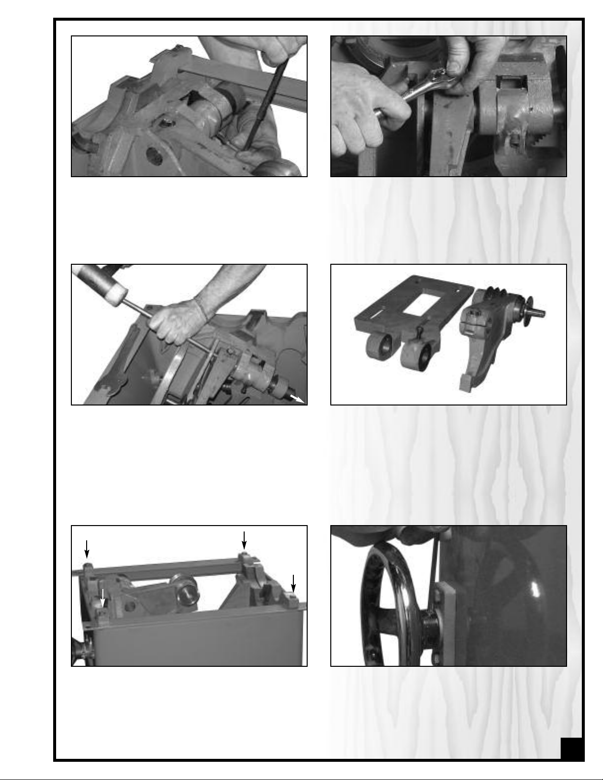
4. Loosen, but do not remove, the cap screw (#36) on
the motor base (#59).
5. Loosen but do not remove the bolt (#2) on the top of
the arbor bracket (#37).
6. Tilt the arbor mechanism to 45° and using a brass
bar or hardwood dowel and mallet, remove and set
aside the pin (#34) through the arbor bracket, chute
and motor base plate.
9. Unfasten and remove the 4 bolts that secure the
trunnions to the cabinet, along with their corresponding washers and nuts.
7. Carefully remove and set aside the motor base
plate (#59) and the arbor bracket (#37).
8. Tilt the arbor mechanism back to 90°.
10. Loosen the set screw (#19) that holds the blade
tilt hand wheel (#58) onto its shaft (#13).
7
 Loading...