


GENERALAireR RESIDENTIAL AIR TREATMENT PRODUCTS
INSTALLATION INSTRUCTIONS
INSTALLER: PLEASE FILL OUT AND MAIL GUARANTEE CARD AFTER INSTALLATION IS COMPLETE. LEAVE INSTALLATION INSTRUCTIONS WITH HOME OWNER
PRECAUTION: The installer should be an experienced service technician. Disconnect electrical power before beginning installation. Do not install where temperatures fall below 32 degrees F or where plenum temperatures exceed 200 degrees F. When wiring into a multi-speed blower circuit see Step 6C.
MODEL 1099
FLOW THROUGH
BYPASS HUMIDIFIER
FOR INSTALLATION ON A VERTICAL PLENUM SURFACE OF ANY FORCED AIR FURNACE
INSTALLATION: The humidifier may be mounted with the 7" outlet to the right or left by inverting the cabinet and reversing the positions of the distributor trough and drain pan. The humidifier may be mounted on the warm or return air plenum with equal efficiency.
See Typical Installations.
ADDITIONAL MATERIALS THAT MAY BE NECESSARY: 1. 1/4" diameter plastic supply tubing or 1/4" copper
supply tubing for hot water applications 2. 7" diameter galvanized by-pass pipe 3. electrical wire and wire nuts
4. air pressure switch (G.F. Model #12500 suggested)
RETURN AIR |
RETURN AIR |
RETURN AIR |
|
WARM AIR |
WARM AIR |
|
DRAIN |
|
|
|
|
DRAIN |
|
|
DRAIN |
|
|
|
|
|
HIGH BOY |
WARM AIR |
COUNTER-FLOW |
WARM AIR |
LOW BOY |
GENERALAireR AC SERIES |
|
|||
|
HIGH EFFICIENCY AIR CLEANER |
|
|
|
1 |
|
|
|
|
|
|
|
|
|
|
|
|
|
|
|
|
|
|
|
|
|
|
|
|
|
|
|
|
ALLOW 2 1/2 INCHES CLEARANCE ABOVE |
|
|
LAISSER 2 PO D'ESPACE LIBRE AU DESSUS |
|||||||||
|
|
|
|
|
|
|
|
|
THIS SURFACE FOR SERVICING |
|
|
DE CETTE SURFACE POUR L'ENTRETIEN |
||||||||
|
|
|
|
|
|
|
|
|
|
|
|
|
|
|
|
|
|
|
|
|
|
|
|
|
|
|
|
|
|
|
Top Of Template |
|
|
Haut de la matrice |
|
|
|||||
|
|
|
|
|
|
|
|
|
|
|
|
|
||||||||
|
|
|
|
|
|
|
|
|
|
TEMPLATE FOR INSTALLING |
|
MATRICE POUR L'INSTALLATION |
||||||||
|
|
|
|
|
|
|
|
|
|
BYPASS HUMIDIFIER |
D'UN HUMIDIFICATEUR DE DÉRIVATION |
|||||||||
|
|
|
|
|
|
|
|
|
FOLLOW INSTRUCTIONS PACKED WITH HUMIDIFIER |
SUIVRE LES INSTRUCTIONS DANS L'EMBALLAGE DE |
||||||||||
|
|
1. |
REMOVE PROTECTIVE PAPER FROM BACK OF |
L'HUMIDIFICATEUR |
||||||||||||||||
|
|
1. |
RETIRER LE PAPIER PROTECTEUR DU DOS DE LA |
|||||||||||||||||
|
|
|
|
|
|
|
|
|
TEMPLATE AND STICK IN LEVEL POSITION. |
MATRICE ET COLLER À NIVEAU. |
||||||||||
|
|
2. |
CENTER PUNCH AND DRILL THE THREE TOP |
2. |
|
|
|
|
|
|
|
|
||||||||
|
|
|
|
|
|
|
|
|
MOUNTING HOLES WITH A 3/32" OR 1/8 " DIA. DRILL. |
3. |
DÉCOUPER LA PARTIE DU MILIEU DE LA MATRICE. |
|||||||||
|
|
|
3. |
CUT OUT CENTER SECTION OF TEMPLATE. |
4. |
RETIRER LE RESTANT DE LA MATRICE. |
||||||||||||||
|
|
|
4. |
REMOVE REMAINING TEMPLATE. |
|
|
|
|
|
|
|
|
|
|||||||
|
|
|
|
|
|
|
|
|
EXTEND THIS LINE FOR LOCATING HOLE ON ADJACENT |
ALLONGER CETTE LIGNE AFIN DE SITUER LE TROU SUR |
||||||||||
|
|
|
|
|
|
|
|
|
PLENUM |
|||||||||||
|
|
|
|
|
|
|
|
|
LE PLÉNUM ADJACENT |
|||||||||||
|
|
|
5. |
INSTALL CABINET WITH THREE TOP SCREWS. |
5. |
|
|
|
|
|
|
|
|
|||||||
|
|
|
6. |
LEVEL CABINET AND TIGHTEN SCREWS. |
6. |
|
|
|
|
|
|
|
|
|||||||
|
|
|
7. |
DRILL AND INSTALL BOTTOM SCREWS. |
7. |
|
|
|
|
|
|
|
|
|||||||
|
|
|
|
|
|
|
|
|
|
CUT ON THIS LINE |
|
|
COUPER SUR CETTE LIGNE |
|
|
|
|
|||
|
|
|
|
|
|
|
|
|
|
|
|
|
|
|
|
|
|
|
|
|
TEMPLATE NO. 1099-29
MATRICE NO. 1099-29
Select location on vertical surface of warm or return air plenum for mounting humidifier. Stick mounting template in place making sure the template is level. Do not install humidifier or 7" bypass pipe where the blanked off ends of a cooling coil will restrict air flow to the humidifier. Extend horizontal centerline from template to the adjacent plenum. Scribe 7” circle 10” to 15” from side of humidifier, on cabinet centerline, using connecting collar as guide.
3 |
Install connecting collar and connect 7" elbow and by-pass pipe to collar and humidifier cabinet. USE UNCRIMPED END IN HUMIDIFIER CABINET. Using holes at top and bottom of humidifier bypass opening drill 2---1/8" holes through bypass pipe and screw bypass pipe to humidifier cabinet.
2
Center punch and drill all six mounting holes as shown on template. Cut out center section of template and 7” hole. Install all six cabinet screws. Install drain pan, evaporator pad and distributor trough using the four slide clips provided.
4 |
COPPER |
|
TUBING |
|
PLASTIC |
|
TUBING |
Mount the self tapping saddle valve on either a cold or a hot water pipe. A side or top mount is best to avoid clogging from pipe sediment. Connect 1/4” O.D. tubing to the saddle valve. Copper tubing requires a brass compression nut and brass sleeve. Plastic tubing requires a brass insert inside the tubing, a plastic sleeve on the outside with a brass compression nut.
NOTE: DO NOT USE PLASTIC TUBING ON HOT WATER OR IN CONTACT WITH ANY HOT PLENUM SURFACE OR DUCT. INSTALLATION OF THIS SADDLE VALVE MUST MEET OR EXCEED LOCAL CODES AND ORDINANCES.
SADDLE VALVE INSTALLATION INSTRUCTIONS
Copper Pipe
1. Retract piercing pin into valve body by turning handle counterclockwise.
2. Screw valve body into upper bracket and tighten.
3. Place rubber gasket over piercing pin.
4. Assemble saddle valve over copper pipe using enclosed screws, nuts and lower bracket.
5. Tighten screws evenly and firmly. Brackets should be parallel. 6. Complete compression connection to saddle valve outlet.
7. Turn handle clockwise to pierce tubing and close saddle valve.
8. Turn handle counterclockwise to open saddle valve, leave open for several seconds to flush dirt from pipe and tubing.
Steel, Brass or Hard Plastic Pipe
1. Shut off water supply and drain pipe.
2. Turn handle clockwise to expose piercing pin and close saddle valve.
3. Place rubber gasket over piercing pin.
4. Drill 1/8" hole in pipe using a hand crank drill to avoid shock hazard. 5. Assemble saddle valve over steel, brass or hard plastic pipe using
enclosed screws, nuts and lower bracket.
6. Tighten screws evenly and firmly. Brackets should be parallel. 7. Complete compression connection to saddle valve outlet.
8. Turn handle counterclockwise to open saddle valve, leave open for several seconds to flush dirt from pipe and tubing.
Threaded Pipe Fittings
1. Turn handle clockwise to expose piercing pin and close saddle valve.
2. Seal valve body threads using pipe tape or sealant. 3. Install valve into 1/8" NPT fitting.
4. Complete compression connection to saddle valve outlet.
5. Turn handle counterclockwise to open saddle valve, leave open for several seconds to flush dirt from pipe and tubing.
6 |
|
|
ACC |
|
|
|
|
115v. |
EAC |
|
|
HUMIDIFIER |
|
6 A |
(HOT) |
HUMIDISTAT |
|
|||
|
115v. SOLENOID |
|||||
60CY. |
|
|||||
|
|
C |
|
|
VALVE |
|
|
|
|
|
|
|
|
|
|
L1 |
FAN CONTROL |
|
SINGLE |
|
|
|
|
|
|
||
|
115v. |
(HOT) |
|
|
|
SPEED |
|
60CY. |
|
|
|
|
BLOWER |
|
|
L2 |
|
|
|
MOTOR |
|
|
|
|
|
|
|
|
6 B |
|
ON-OFF |
|
|
|
|
|
SWITCH |
|
HUMIDIFIER |
||
|
|
|
|
HUMIDISTAT |
115v. |
|
|
|
|
|
SOLENOID |
||
|
|
|
|
|
|
|
|
|
|
|
|
|
VALVE |
|
6 C |
ON-OFF |
12500 AIR |
|
HUMIDIFIER |
|
|
PRESSURE |
|
115v. SOLENOID |
|||
|
SWITCH |
|
||||
|
|
L1 |
|
NO SWITCH |
|
VALVE |
|
115v. |
(HOT) |
|
C |
HUMIDISTAT |
|
|
60CY. |
|
|
|
|
|
|
|
L2 |
|
|
|
|
5
Attach solenoid valve to side of humidifier cabinet with flow arrow pointing up, using thumb nuts provided. Do not reverse brass fittings as valve will not function if flow is reversed. Inlet and outlet ports on valve may be reversed by loosening hex nut on solenoid coil and rotating valve 1/2 turn. Assemble distributor tube so that it is directed into the center opening of the distributor trough cover. Connect 1/4" water supply tube to brass filter at inlet of solenoid.
DO NOT USE PLASTIC TUBING IN CONTACT WITH ANY HOT PLENUM SURFACE OR DUCT. IF USING PLASTIC TUBING, USE TUBE SUPPORT PROVIDED.
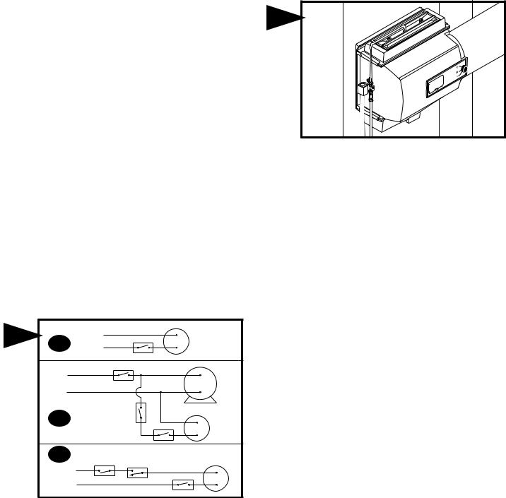
INSTRUCTIONS FOR WIRING
FIG. 6A WITH FURNACE CIRCUIT BOARD
On furnaces with output terminals ACC, or EAC check output voltage to determine if terminals are 115V.
FIG. 6B WITH SINGLE SPEED BLOWER MOTOR
On furnaces with single speed blowers, wire the 115v. solenoid valve in parallel with the blower circuit and install a manual on-off switch in series with the 115v. solenoid valve.
FIG. 6C WITH TWO SPEED BLOWER MOTOR OR OUTSIDE
FURNACE CIRCUIT
On furnaces with a two speed blower motor or when wiring within the furnace is not practical, the humidifier and a Model 12500 Air Pressure Switch may be wired from a continuous 115 volt power source. Install the on/off switch and Air Pressure Switch in series with the 115v. solenoid valve on the hot or black wire. The Air Pressure Switch will detect furnace operation and supply power to the humidifier accordingly.
NOTE: ALL WIRING SHOULD COMPLY WITH LOCAL ELECTRICAL CODES.
 Loading...