


SETUP & OPERATION MANUAL |
|
FEATURES |
7”MOLDER |
|
|
Cast-iron table and head for smooth vibra- |
|
tion free performance. |
|
Heavy-duty cast-iron dovetailed column, |
|
precision machined for smooth cutter |
|
head height adjustment. |
|
Precision high-speed, sealed, |
|
pre-lubricated bearings. |
|
Independent, variable speed feed motor |
|
provides added control for precision, tear- |
|
out free performance with hardwoods and |
|
stock with figured grain. |
|
Jackscrew style cutter head adjustment |
|
system. |
|
Triple guide bearing design allows for |
|
curved moldings |
|
Easily adjustable guide fence system; sim- |
|
ple lock knob design, to keep stock in-line |
|
through the cut. |
|
In-feed and out-feed table extension |
|
rollers, for added support with longer work- |
|
pieces. |
|
Magnetic 2-step safety switch to prevent |
|
unwanted or unintentional start-up is |
|
equipped with an extra-large easy access |
|
stop panel and a lock-out key to prevent |
|
unauthorized use of the molder. |
|
Built-in dust hood with 4” dust outlet. |
|
Variable feed speed. |
|
SPECIFICATIONS |
|
MAXIMUM PLANING WIDTH |
|
7” (178 MM) |
|
MAXIMUM MOLDING WIDTH |
|
6 3⁄4” (171 mm) |
|
MAXIMUM THICKNESS OF STOCK |
|
8” (203 mm) |
|
MINIMUM THICKNESS OF STOCK |
|
1⁄4” (6 mm) |
|
MINIMUM LENGTH OF STOCK |
|
8” (203 mm) |
|
MAXIMUM DEPTH OF CUT (PLANING) |
MODEL |
1⁄8” (3 mm) |
|
MAXIMUM DEPTH OF CUT (MOLDING) |
|
3⁄4” (19 MM) |
|
NUMBER OF KNIVES |
|
2 |
#30-120 M1 |
CUTTER HEAD SPEED |
|
7000 RPM |
|
FEED SPEED (VARIABLE) |
|
3 - 20 FPM (0.9 - 6.1 MPM) |
|
MOTOR |
|
2 HP 220 V,1 PH, 12 A |
|
OVERALL DIMENSIONS (L X W X H) |
|
32” X 27 1⁄2” X 51” (813 X 699 X 1295 MM) |
|
WEIGHT |
|
242 LBS (110 KG) |
Version 2 _ Revision 1 - November 11, 2013 (s/n 32228713) |
|
|
|
© Copyright General® International 11/2013 |

GENERAL® INTERNATIONAL
8360 Champ-d’Eau, Montreal (Quebec) Canada H1P 1Y3 Telephone (514) 326-1161 • Fax (514) 326-5555 • www.general.ca
THANK YOU for choosing this General® International model 30-120 M1 7” Molder. This molder has been carefully tested and inspected before shipment and if properly used and maintained, will provide you with years of reliable service. For your safety, as well as to ensure optimum performance and trouble-free operation, and to get the most from your investment, please take the time to read this manual before assembling, installing and operating the unit.
The manual’s purpose is to familiarize you with the safe operation, basic function, and features of this molder as well as the set-up, maintenance and identification of its parts and components. This manual is not intended as a substitute for formal woodworking instruction, nor to offer the user instruction in the craft of woodworking. If you are not sure about the safety of performing a certain operation or procedure, do not proceed until you can confirm, from knowledgeable and qualified sources, that it is safe to do so.
Once you’ve read through these instructions, keep this manual handy for future reference.
Disclaimer: The information and specifications in this manual pertain to the unit as it was supplied from the factory at the time of printing. Because we are committed to making constant improvements, General ® International reserves the right to make changes to components, parts or features of this unit as deemed necessary,without prior notice and without obligation to install any such changes on previously delivered units. Reasonable care is taken at the factory to ensure that the specifications and information in this manual corres-
ponds with that of the unit with which it was supplied. However, special orders and “after factory” modifications may render some or all information in this manual inapplicable to your machine. Further, as several generations of this model of molder and several versions of this manual may be in circulation, if you own an earlier or later version of this unit, this manual may not depict your machine exactly. If you have any doubts or questions contact your retailer or our support line with the model and serial number of your unit for clarification.

GENERAL® INTERNATIONAL WARRANTY
All component parts of General® International and Excalibur by General International® products are carefully inspected during all stages of production and each unit is thoroughly inspected upon completion of assembly.
Limited Lifetime Warranty
Because of our commitment to quality and customer satisfaction, General® International agrees to repair or replace any part or component which upon examination, proves to be defective in either workmanship or material to the original purchaser for the life of the tool. However, the Limited Lifetime Warranty does not cover any product used for professional or commercial production purposes nor for industrial or educational applications. Such cases are covered by our Standard 2-year Limited Warranty only.The Limited Lifetime Warranty is also subject to the “Conditions and Exceptions” as listed below.
Standard 2-Year Limited Warranty
All products not covered by our lifetime warranty including products used in commercial, industrial and educational applications are warranted for a period of 2 years (24 months) from the date of purchase. General® International agree to repair or replace any part or component which upon examination, proves to be defective in either workmanship or material to the original purchaser during this 2-year warranty period, subject to the “conditions and exceptions” as listed below.
To file a Claim
To file a claim under our Standard 2-year Limited Warranty or under our Limited Lifetime Warranty, all defective parts, components or machinery must be returned freight or postage prepaid to General® International, or to a nearby distributor, repair center or other location designated by General® International. For further details call our service department at 1-888-949-1161 or your local distributor for assistance when filing your claim.
Along with the return of the product being claimed for warranty, a copy of the original proof of purchase and a “letter of claim” must be included (a warranty claim form can also be used and can be obtained, upon request, from General® International or an authorized distributor) clearly stating the model and serial number of the unit (if applicable) and including an explanation of the complaint or presumed defect in material or workmanship.
CONDITIONS AND EXCEPTIONS:
This coverage is extended to the original purchaser only. Prior warranty registration is not required but documented proof of purchase i.e. a copy of original sales invoice or receipt showing the date and location of the purchase as well as the purchase price paid, must be provided at the time of claim.
Warranty does not include failures, breakage or defects deemed after inspection by General® International to have been directly or indirectly caused by or resulting from; improper use, or lack of or improper maintenance, misuse or abuse, negligence, accidents, damage in handling or transport, or normal wear and tear of any generally considered consumable parts or components.
Repairs made without the written consent of General® International will void all warranty.

TABLE OF CONTENTS
Rules for safe operation . . . . . . . . . . . . . . .5 Electrical requirements . . . . . . . . . . . . . . .6
Grounding instructions . . . . . . . . . . . . . . . . . . . . . . .6 Circuit capacity . . . . . . . . . . . . . . . . . . . . . . . . . . . . .6 Extension cords . . . . . . . . . . . . . . . . . . . . . . . . . . . . .6
Identification of main parts
and components . . . . . . . . . . . . . . . . . . . .7
Unpacking . . . . . . . . . . . . . . . . . . . . . . . . .8
List of contents . . . . . . . . . . . . . . . . . . . . . . . . . . . . . .8 Additional requirements for set up . . . . . . . . . . . . .8
Placement within the shop / |
|
Establishing a safety zone . . . . . . . . . . . . . |
9 |
Preparation & Clean up . . . . . . . . . . . . . . . .9
Install the cutter head height adjustment handwheel . . . . . . . . . . . . . . . . . . . . . . . . . . . . . . . . .9 Remove the styrofoam block . . . . . . . . . . . . . . . . . .9 Remove the protctive plastic sheet . . . . . . . . . . . . .9 Clean up . . . . . . . . . . . . . . . . . . . . . . . . . . . . . . . . . .10
Assembly instructions . . . . . . . . . . . . . . .10
Mount the magnetic safety switch . . . . . . . . . . . .10 Attach the leveling feet to the stand . . . . . . . . . . .10 Install the belt on the drive pulley . . . . . . . . . . . . .10
Basic adjustments & controls . . . . . . . .11-13
Raising/Lowering the cutter head for
depth of cut . . . . . . . . . . . . . . . . . . . . . . . . . . . . . . .11 Connecting to a power source . . . . . . . . . . . . . . .12 On/off power switches . . . . . . . . . . . . . . . . . . . . . .12 On/off magnetic power switch . . . . . . . . . . . . . . .12 Feed motor switch with safety key . . . . . . . . . . . .12 Thermal relay/circuit breaker . . . . . . . . . . . . . . . .13 Changing feed speed . . . . . . . . . . . . . . . . . . . . . .13
Checking/Setting the knives for planing 13-15
Setting one knife parallel to the table . . . . . . . . .14
Setting the height of the second knife . . . . . . . . .15
Adjusting the feed rollers . . . . . . . . . . .16-17
Adjusting the feed roller height . . . . . . . . . . . . . . |
.16 |
Adjusting the feed roller pressure . . . . . . . . . . . . . |
17 |
To install molding knives . . . . . . . . . . . . . |
18 |
Operating instructions . . . . . . . . . . . . .20-24
Basic principles of planing/molding . . . . . . . . . .20 Selecting boards suitable for planing/molding .20 Rated limits of this molder/planer . . . . . . . . . . . . .20 Connecting to a dust collector . . . . . . . . . . . . . . .21 Checklist before starting . . . . . . . . . . . . . . . . . . . . .21 Planing . . . . . . . . . . . . . . . . . . . . . . . . . . . . . . . . . . .22 Molding . . . . . . . . . . . . . . . . . . . . . . . . . . . . . . . . . . .23 Repeat/multiple passes (for planing & molding) .23 Molding curved pieces using the elliptical jig . .24
Maintenance . . . . . . . . . . . . . . . . . . . .25-19
Periodic maintenance . . . . . . . . . . . . . . . . . . . . . .25 Drive chain/gear lubrication . . . . . . . . . . . . . . . . .26 Inspecting/replacing cutte head knives . . . . . . .26
Recommended optional accessories . . . . .27 Parts list & diagrams . . . . . . . . . . . . . .28-34

RULES FOR SAFE OPERATION
To help ensure safe operation, please take a moment to learn the machine’s applications and limitations, as well as poten- tial hazards. General® International disclaims any real or implied warranty and holds itself harmless for any injury that may result from improper use of its equipment.
1.Do not operate this molder when tired, distracted, or under the effects of drugs, alcohol or any medication that impairs reflexes or alertness.
2.The working area should be well lit, clean and free of debris.
3.Keep children and visitors at a safe distance when the molder is in operation; do not permit them to operate the molder.
4.Childproof and tamper proof your shop and all machinery with locks, master electrical switches and switch keys, to prevent unauthorized or unsupervised use.
5.Stay alert! Give your work your undivided attention. Even a momentary distraction can lead to serious injury.
6.Fine particulate dust is a carcinogen that can be hazardous to health. Work in a well-ventilated area and whenever possible use a dust collector. Wear face, eye, ear, respiratory and body protection devices.
7.Do not wear loose clothing, gloves, bracelets, necklaces or other jewelry while the molder is in operation. Wear protective hair covering to contain long hair and wear non-slip footwear.
8.Be sure that adjusting wrenches, tools, drinks and other clutter are removed from the machine and/or the table surface before operating.
9.Keep hands well away from knives and all moving parts. Use a push stick to feed stock, and a brush, not hands, to clear away chips and dust.
10.Be sure that the knives are securely installed in the cutter head.
11.Always use clean, properly sharpened knives. Dirty or dull knives are unsafe and can lead to accidents.
12.Inspect stock and remove all foreign objects before planing. Make sure that any stock you plane is clean and free of any dirt, nails,staples, tiny rocks or any other foreign objects that may damage the molder knives. Only process natural solid wood boards. Never plane MDF,particle board, plywood, laminates or other synthetic materials.
13.Do not push or force stock into the cutter head. The molder will perform better and safer when working at the rate for which it was designed.
14.Kickback is when the workpiece is ejected at high speeds by the force of the cutter head. To minimize the risk of injury from kickback, use proper feeding technique and stand to one side, out of the path of a potential kickback.
15.Select appropriate feed speed for the stock being planed: high speed for softwood and slow for hardwoods.
16.Place stock firmly against the table and use suitable in-feed and out-feed support if stock is too long.
17.Keep guards in place and in working order. If a guard must be removed for maintenance or cleaning make sure it is properly attached before using the machine again.
18.Use of parts and accessories NOT recommended by GENERAL®INTERNATIONAL may result in equipment malfunction or risk of injury.
19.Never stand or lean on machinery. Serious injury could result if the tool is tipped over or if the cutting tool is unintentionally contacted.
20.Always disconnect the tool from the power source before servicing or changing accessories such as knives, or before performing any maintenance or cleaning, or if the machine will be left unattended.
21.Make sure that the switch is in the “OFF” position before plugging in the power cord.
22.Make sure the tool is properly grounded. If equipped with a 3-prong plug it should be used with a three-pole receptacle. Never remove the third prong.
23.Do not use this molder for other than its intended use. If used for other purposes, GENERAL INTERNATIONAL disclaims any real implied warranty and holds itself harmless for any injury, which may result from that use.
5
ELECTRICAL REQUIREMENTS
BEFORE CONNECTING THE MACHINE TO THE POWER SOURCE, VERIFY THAT THE VOLTAGEOF YOUR POWER SUPPLY CORRESPONDS WITH THE VOLTAGE SPECIFIED ON THE MOTOR I.D. NAMEPLATE. A POWER SOURCE WITH GREATER VOLTAGE THAN NEEDED CAN RESULT IN SERIOUS INJURY TO THE USER AS WELL AS DAMAGE TO THE MACHINE. IF IN DOUBT, CONTACT A QUALIFIED ELECTRICIAN BEFORE CONNECTING TO THE POWER SOURCE.
THIS TOOL IS FOR INDOOR USE ONLY. DO NOT EXPOSE TO RAIN OR USE IN WET OR DAMP LOCATIONS.
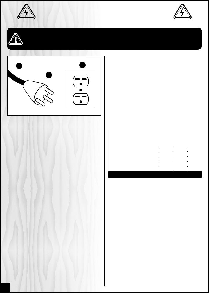
A C
B
GROUNDING INSTRUCTIONS
In the event of an electrical malfunction or short circuit, grounding reduces the risk of electric shock to the operator. The motor of this machine is wired for 220V single phase operation and is equipped with a 3-conductor cord A and a 3-prong grounded plug B to fit a matching grounding type receptacle C.
DO NOT MODIFY THE PLUG PROVIDED ! If it will not fit your receptacle, have the proper receptacle installed by a qualified electrician.
CHECK with a qualified electrician or service person if you do not completely understand these grounding instructions, or if you are not sure the tool is properly grounded.
CIRCUIT CAPACITY
Make sure that the wires in your circuit are capable of handling the amperage draw from your machine, as well as any other machines that could be operating on the same circuit. If you are unsure, consult a qualified electrician. If the circuit breaker trips or the fuse blows regularly, your machine may be operating on a circuit that is close to its amperage draw capacity. However,if an unusual amperage draw does not exist and a power failure still occurs, contact a qualified technician or our service department.
EXTENSION CORDS
The use of an extension cord is not generally recommended for 220V equipment. If you find it necessary, use only 3-wire extension cords that have 3-prong grounding plug and a matching 3-pole receptacle that accepts the tool’s plug. Repair or replace a damaged extension cord or plug immediately.
If you find it necessary to use an extension cord with your machine make sure the cord rating is suitable for the amperage listed on the motor I.D. plate. An undersized cord will cause a drop in line voltage resulting in loss of power and overheating. The accompanying chart shows the correct size extension cord to be used based on cord length and motor I.D. plate amp rating. If in doubt, use the next heavier gauge. The smaller the number, the heavier the gauge.
|
|
|
|
|
|
|
TABLE - MINIMUM GAUGE FOR CORD |
|
|||||
|
|
|
|
|
|
|
AMPERE |
|
TOTAL LENGTH OF CORD IN FEET |
|
|||
220 VOLTS |
25 FEET |
50 FEET |
100 FEET |
150 FEET |
||
RATING |
||||||
|
|
|
AWG |
|
|
|
< 5 |
-------> |
18 |
16 |
16 |
14 |
|
6 TO 10 |
-------> |
18 |
16 |
14 |
12 |
|
10 TO 12 |
-------> |
16 |
16 |
14 |
12 |
|
12 TO 16 |
-------> |
14 |
12 |
* NR |
* NR |
|
* NR = Not Recommended
6

|
7” MOLDER |
|
||
|
30-120 M1 |
|
|
|
IDENTIFICATION OF MAIN PARTS AND COMPONENTS |
||||
|
|
|
|
A |
|
|
C |
|
|
|
D |
|
|
B |
|
|
|
|
|
|
E |
|
F |
G |
|
|
|
|
E |
|
H |
I |
|
|
|
|
|
|
|
|
J |
|
|
|
|
|
|
|
L |
|
K |
|
|
|
|
|
|
|
M |
A- CUTTER HEAD HEIGHT |
|
|
H- FEED SPEED CONTROL KNOB |
|
|
ADJUSTMENT HANDWHEEL |
|
|
I- FEED MOTOR SWITH WITH SAFETY KEY |
B- |
BELT COVER |
|
|
|
|
|
J- THERMAL RELAY |
||
C- DUST HOOD |
|
|
||
|
|
K- PANEL |
||
D- FEED MOTOR |
|
|
||
|
|
L- MAGNETIC SWITCH WITH LOCK-OUT KEY |
||
E- TABLE EXTENSION ROLLERS |
|
|
||
|
|
M- STAND |
||
F- |
FENCES |
|
|
|
|
|
|
||
G- FENCE LOCK KNOBS |
|
|
|
|
|
|
|
|
7 |

UNPACKING
Carefully unpack and remove the molder and its components from the box and check for damaged or missing items as per the list of contents below.
NOTE: Please report any damaged or missing items to your General International distributor immediately.
LIST OF CONTENTS |
QTY |
|
A- |
MOLDER......................................................................... |
1 |
B- |
HANDWHEEL .................................................................. |
1 |
|
LEVELING FOOT & HARDWARE: |
|
C - HEX NUT ......................................................................... |
4 |
|
D - |
FLAT WASHER ................................................................. |
4 |
E - |
LEVELING FOOT ............................................................. |
4 |
|
ELLIPTICAL JIG & HARDWARE: |
|
F - |
ELLIPTICAL JIG................................................................ |
1 |
G - |
IDLER BEARING .............................................................. |
1 |
H - |
CAP SCREW M8 X 1.25 - 110L ..................................... |
2 |
I - |
WASHER.......................................................................... |
2 |
J - |
BUTTON HEAD SCREW M6 X 1.0 - 16L. ........................ |
2 |
|
TOOLS |
|
K - |
SCREWDRIVER ............................................................... |
1 |
L - |
22-24 MM OPEN END WRENCH .................................. |
1 |
M - 17-19 MM OPEN END WRENCH .................................. |
1 |
|
N - |
12-14 MM OPEN END WRENCH .................................. |
1 |
O - |
7-8 MM OPEN END WRENCH ...................................... |
1 |
P - |
6 MM ALLEN KEY .......................................................... |
1 |
Q - 4 MM ALLEN KEY .......................................................... |
1 |
|
R- |
2 MM ALLEN KEY ........................................................... |
1 |
S - |
4 MM T-HANDLE WRENCH............................................. |
1 |
ADDITIONAL REQUIREMENTS FOR SET UP
•Extra person for help with lifting
•Feeler gauge set (0.030”)
•3 mm Allen key
•Gauge block
8
A
B
F
G H
D
C
E
I
J
K
L
M T
N
O
P
Q R

PLACEMENT WITHIN THE SHOP / ESTABLISHING A SAFETY ZONE
THIS MODEL 30-120 M1 7” MOLDER IS HEAVY.DO NOT OVER-EXERT. THE HELP OF AT LEAST ONE ASSISTANT OR A HOIST WILL BE NEEDED FOR THE FOLLOWING STEP.
TO LIMIT THE RISK OF SERIOUS INJURY OR DAMAGE TO THE MACHINE, ANY EQUIPMENT USED TO LIFT THIS MACHINE SHOULD HAVE A RATED CAPACITY IN EXCESS OF 242 LBS (110 KG).
PLACEMENT WITHIN THE SHOP
This machine should be installed and operated only on |
|
|
|
|
|
|
|
|
a solid, flat and stable floor that is able to support the |
|
|
|
|
|
|
|
|
weight of the molder and the operator. Using the dimen- |
|
|
|
|
|
|
|
|
sions shown as a guideline, plan for placement within |
|
|
|
|
|
|
|
|
your shop that will allow the operator to work unencum- |
|
51” |
|
|
|
|
||
bered and unobstructed by foot traffic (either passing |
|
|
|
|
|
|
|
|
shop visitors or other shop workers) or other tools or |
|
|
|
|
|
|
|
|
machinery. |
|
|
|
|
|
|
|
|
ESTABLISHING A SAFETY ZONE |
|
|
|
|
|
|
|
|
For shops with frequent visitors or multiple operators, it is |
|
|
|
|
|
|
|
|
|
|
|
|
|
|
|
|
|
advisable to establish a safety zone around shop |
|
|
|
|
|
|
|
|
machinery. A clearly defined “no-go” zone on the floor |
|
|
|
|
|
|
|
|
around each machine can help avoid accidents that |
|
|
|
|
32” |
|
27½” |
|
could cause injury to either the operator or the shop vis- |
|
|
|
|
|
|
||
itor. It is advisable to take a few moments to either paint |
|
|
|
|
|
|
|
|
|
|
|
|
|
|
|
|
|
(using non-slip paint) or using tape, define on the floor the limits or perimeter of each machines safety zone. Take steps to ensure that all operators and shop visitors are aware that these areas are off limits whenever a machine is
running for everyone but the individual operating the unit.
PREPARATION & CLEAN UP
INSTALL THE CUTTER HEAD HEIGHT ADJUSTMENT HANDWHEEL REMOVE THE STYROFOAM BLOCK
B
A
C
1.Using a 3 mm Allen key, loosen the set screw A on the handwheel.
2.Fit the handwheel shaft onto the shaft, B.
3.Tighten the set screw C to secure the handwheel in place.
REMOVE THE PROTECTIVE PLASTIC SHEET
1.Loosen the fence lock knobs F and remove the fences G and H.
2.Remove the protective plastic sheet I from the table.
D
E
To limit the potential for damage in transport, this molder is shipped from the factory with the molder’s head sitting on a styrofoam block for support.
1.Loosen the cutter head lock lever D by turning it counterclockwise. Important! Attempting to adjust the height of the cutter head with it’s lock lever tightened will cause premature wear of the locking mechanism.
2.Rotate the handwheel counterclockwise to raise the cutter head enough to remove the styrofoam block E.
H G
F
I
9
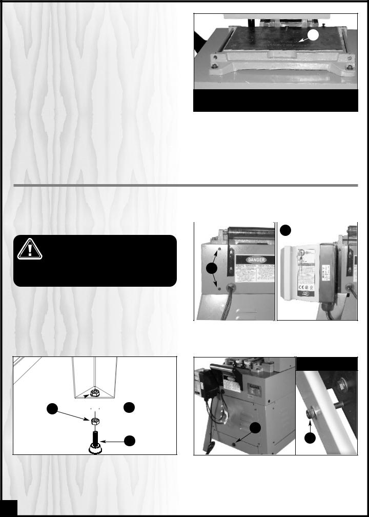
CLEAN UP
The protective coating on the table, K, prevents rust from forming during shipping and storage. Remove it by rubbing with a rag dipped in kerosene, mineral spirits or paint thinner.
Important: Dispose of potentially flammable solventsoaked rags according to manfacturer’s safety recommendations.
A putty knife, held flat to avoid scratching the surface, may also be used to scrape off the coating followedby clean-up with solvent.
Note: Avoidrubbing the molder’spainted surfaces,as many solvent-basedproducts will remove paint.
K
Tip: To prevent rust, apply a light coating of paste wax or use regular applications of any after-market surface protectant or rust inhibitor.
ASSEMBLY INSTRUCTIONS
For your convenience this molder is shipped from the factory partially assembled and requires only minimal assembly and set up before being put into service.
MOUNT THE MAGNETIC SAFETY SWITCH |
|
|
|
|
|
|
B |
||
|
|
|
|
|
|
SERIOUS PERSONAL INJURY COULD OCCUR |
|
|
|
|
|
|
|
|
|
IF YOU CONNECT THE MACHINE TO THE |
|
|
|
|
POWER SOURCE BEFORE YOU HAVE COM- |
|
|
|
|
PLETED THE INSTALLATION AND ASSEMBLY |
|
|
|
|
STEPS. DO NOT CONNECT THE MACHINE TO |
A |
||
|
THE POWER SOURCE UNTIL INSTRUCTED TO |
|
|
|
|
DO SO. |
|
|
|
Attach the magnetic safety swith to the right side of the molder using the 2 button head screws already mouned to the stand A as shown in B.
ATTACH THE LEVELING FEET TO THE STAND
B 

 C
C
A
Attach the 4 leveling feet A to the stand using 2 nuts B and 1 washer C.
Note: After the stand is placed in its final location, level the feet by loosening the top nut, adjusting lower nut up or down on the screw stem as needed, then tightening down the top nut.
INSTALL THE BELT ON THE DRIVE PULLEY
CLOSE UP
D
D
Note: To limit the potential for damage in transport, this molder is shipped from the factory with the motor mounting plate secured to the stand with a cap screw D.
1.Using the supplied 6 mm allen key, loosen and remove the cap screw and flat washer D that secures the motor mounting plate to the stand.
10

H
F
F
G
F
2.Using the supplied 4 mm T-handle wrench, loosen and remove the 3 Allen screws F, then remove the upper pulley cover G.
Note: The drive belt is already installed on the upper pulley H.
I I
I I
3.Using the supplied 4 mm T-handle wrench, unscrew and remove the 4 button head screws I that secure the motor cover panel to the stand.
J
K
4.Remove the motor cover panel to access the motor J.
5.With the help of an assistant, lift the motor up and install the other end of the belt in the slot on the lower pulley K.
6. |
Re-install the motor cover panel and upper pul- |
BASIC ADJUSTMENTS & CONTROLS |
ley cover. |
|
|
|
|
RAISING/LOWERING THE CUTTER HEAD FOR DEPTH OF CUT |
|
The depth of cut is set by raising or lowering the cutter head. |
|
DOWN |
B |
|
UP |
A |
C |
|
||
|
|
A |
1/3 x  = 1/32”
1.Loosen the cutter head lock lever A by turning it counterclockwise.
Important! Attempting to adjust the height of the cutter head with it’s lock lever tightened will cause premature wear of the locking mechanism.
2.Use handwheel B to adjust the cutter head height to the desired depth of cut, turning:
-Clockwise to raise the cutter head.
-Counterclockwise to lower the cutter head.
Note: the depth gauge, C, on the front of the machine can be used as a reference but it is not intended for high precision measurements
3.Re-tighten lock lever A to secure the cutter head in position.
NOTE: 1/3 of a clockwise rotation of the crank handle will raise the cutter head by 1/32”. 1/3 of a counterclockwise rotation will lower the cutter head by 1/32”.
11
 Loading...