


 Powerful 2 HP motor with thermal overload protection.
 Front and rear fold-down extension tables (12 L x 15 1/4 W) with end rollers for smooth easy stock feeding.
 Top mounted return rollers for smooth stock handling for consecutive planning/multiple passes.
 Convenient power cord storage brackets and inset lifting handles.
 Dual position depth of cut adjustment handle mounts left or right – one full rotation equals 1/16”.
 Dual feed speeds for smooth planning with either soft or hard wood.
 Adjustable pre-set depth gauge for accurate repeat cuts.
 Easy to read graduated scale in both inches and metric indicates workpiece thickness.
 Safety On/Off switch with key. Unit cannot be started when key is removed from switch.
Snipe eliminating head lock.
Depth of cut indicator.
Includes magnetic knife setting guide.
TABLE AREA WITH EXTENSIONS (L X W) 36 5/8” X 15 1⁄4” (930 x 387 mm)
MAXIMUM PLANING WIDTH 13” (330 mm)
MAXIMUM THICKNESS OF STOCK 6” (152 mm)
MINIMUM THICKNESS OF STOCK 1⁄8” (3 mm)
MINIMUM LENGTH OF STOCK 5” (127 mm)
MAXIMUM DEPTH OF CUT (FULL WIDTH) 1⁄16” (1.5 mm)
KNIVES
2 - DOUBLE EDGED
CUTTERHEAD SPEED 9500 RPM
FEED SPEEDS (2) 18 & 26 FPM
CUTS PER INCH 88 / 61
MOTOR
2 HP, 120 V, 1 Ph, 15 A
REVISION 1 - JUNE 7/07
© COPYRIGHT GENERAL INTERNATIONAL 06/2007

GENERAL® INTERNATIONAL
8360 Champ-d’Eau, Montreal (Quebec) Canada H1P 1Y3 Telephone (514) 326-1161 • Fax (514) 326-5555 • www.general.ca
THANK YOU for choosing this General® International model 30-010 M1 13” single surface planer. This planer has been carefully tested and inspected before shipment and if properly used and maintained, will provide you with years of reliable service. To ensure optimum performance and trouble-free operation, and to get the most from your investment, please take the time to read this manual before assembling, installing and operating the unit.
The manual’s purpose is to familiarize you with the safe operation, basic function, and features of this planer as well as the set-up, maintenance and identification of its parts and components. This manual is not intended as a substitute for formal woodworking instruction, nor to offer the user instruction in the craft of woodworking. If you are not sure about the safety of performing a certain operation or procedure, do not proceed until you can confirm, from knowledgeable and qualified sources, that it is safe to do so.
Once you’ve read through these instructions, keep this manual handy for future reference.
GENERAL ® INTERNATIONAL WARRANTY
All component parts of General® International machinery are carefully tested and inspected during all stages of production, and each machine is thoroughly inspected upon completion of assembly. Because of our commitment to quality and customer satisfaction, General® International agrees to repair or replace, within a period of 24 months from date of purchase, any genuine part or parts which, upon examination, prove to be defective in workmanship or material. In order to obtain this warranty, all defective parts must be returned freight pre-paid to General® International Mfg. Co., Ltd. Repairs attempted without our written authorization will void this warranty.
Disclaimer: The information and specifications in this manual pertain to the unit as it was supplied from the factory at the time of printing. Because we are committed to making constant improvements, General International reserves the right to make changes to components, parts or features of this unit as deemed necessary, without prior notice and without obligation to install any such changes on previously delivered units. Reasonable care is taken at the factory to ensure that the specifications and information in this manual corresponds with that of the unit with which it was supplied. However, special orders and “after factory”
modifications may render some or all information in this manual inapplicable to your machine. Further, as several generations of this model of planer and several versions of this manual may be in circulation, if you own an earlier or later version of this unit, this manual may not depict your machine exactly. If you have any doubts or questions contact your retailer or our support line with the model and serial number of your unit for clarification.

Rules for Safe Operation
To help ensure safe operation, please take a moment to learn the machine’s applications and limitations, as well as potential hazards. General® International disclaims any real or implied warranty and holds itself harmless for any injury that may result from improper use of its equipment.
1.Read, understand and follow all safety warnings and instructions in the supplied Operator’s Manual.
2.Do not operate the planer when tired, distracted, or under the effects of drugs, alcohol or any medication that impairs reflexes or alertness.
3.The working area should be well lit, clean and free of debris.
4.Keep children and shop visitors at a safe distance when the planer is in operation; do not permit them to operate the planer.
5.Childproof and tamper proof your shop and all machinery with locks, master electrical switches and switch keys, to prevent unauthorized or unsupervised use.
6.Stay alert! Give your work your undivided attention. Even a momentary distraction can lead to serious injury.
7.Wear approved safety glasses, dust mask and hearing protection, and do not wear loose clothing, gloves, bracelets, necklaces or jewelry while operating the planer. Wear protective hair covering to contain long hair and wear non-slip footwear.
8.Fine particulate dust is a carcinogen that can be hazardous to health. Work in a well-ventilated area and whenever possible use a dust collector.
9.Keep hands well away from the cutterhead and all moving parts. Do not clear chips and sawdust away with hands, use a brush.
10.Be sure that wrenches, tools, drinks and other clutter are removed from the machine and/or the table surfaces before operation.
11.Kickback is when the workpiece is ejected at high speeds by the force of the cutterhead. To minimize the risk of injury from kickback, use proper feeding technique and stand to one side, out of the path of a potential kickback.
12.Be sure the blades are securely installed in the cutterhead and in proper cutting direction before operation.
13.Make sure the cutterhead has gained full operating speed before feeding stock into the planer.
14.Always use clean, properly sharpened knives in the cutterhead. Dirty or dull knives are unsafe and can lead to accidents.
15.Inspect stock and remove all foreign objects before planing. Make sure that any stock you plane is clean and free of dirt, nails, staples, tiny rocks or any other foreign objects that may damage the blades. Only process natural solid wood boards. Never plane MDF, particle board, plywood, laminates or other synthetic materials.
16.Do not push or force stock into the cutterhead. The planer will perform better and safer when working at the rate for which it was designed.
17.The maximum depth of cut for one pass is 1/8” for a board of 5 -1/2" or less In width and 1/16" for a board wider than 5 -1/2". Never attempt to remove more material than the maximum in any single pass.
18.Select appropriate feed speed for the stock being planed: high speed for softwood and slow for hardwoods.
19.Place stock firmly against the table and use suitable in-feed and out-feed support if stock is too long.
20.Keep guards in place and in working order. If a guard must be removed for maintenance or cleaning make sure it is properly attached before using the machine again.
21.Never leave the machine unattended while running or with the power “ON”.
22.Always turn off and disconnect from power source before servicing or changing accessories, blades, or before performing any maintenance or adjustments.
23.Make sure the switch is in the "off" position before plugging in the power cord.
24.Make sure planer is properly grounded. If equipped with a 3-prong plug it should be used with a three-pole receptacle. Never remove the third prong.
25.Use only parts and accessories that are designed for use with this planer. The use of parts or accessories NOT recommended by General International may result in equipment malfunction and an increased risk of injury.
26.Do not use this planer fro anything other than its intended use. If used for other, General International disclaims any real or implied warranty and holds itself harmless for any injury which may result from that use.
ELECTRICAL REQUIREMENTS
Before connecting the machine to the power source, verify that the voltage of your power supply corresponds with the voltage specified on the motor I.D. nameplate. A power source with greater voltage than needed can result in serious injury to the user as well as damage to the machine. If in doubt, contact a qualified electrician before connecting to the power source.
This tool is for indoor use only. Do not expose to rain or use in wet or damp locations.
GROUNDING INSTRUCTIONS
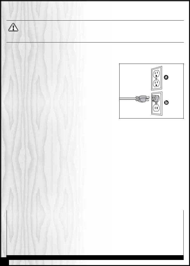
In the event of an electrical malfunction or short circuit, grounding reduces the risk of electric shock. The motor of this machine is wired for 110V single phase operation and is equipped with a 3-conductor cord and a 3-prong grounded plug to fit a grounded type receptacle, . Do not remove the 3rd prong (grounding pin) to make it fit into an old 2- hole wall socket. If an adaptor plug is used,
  , it must be attached to the metal screw of the receptacle.
Note: The use of an adaptor plug is illegal in some areas. Check your local codes.
DO NOT MODIFY THE PLUG PROVIDED.
If it will not fit your receptacle, have the proper receptacle installed by a qualified electrician.
CHECK with a qualified electrician or service person if you do not completely understand these grounding instructions, or if you are not sure the tool is properly grounded.
EXTENSION CORDS
USE ONLY 3-WIRE EXTENSION CORDS THAT HAVE 3-PRONG GROUNDING PLUGS AND 3-POLE RECEPTACLES THAT ACCEPT THE TOOLS’ PLUG. REPAIR OR REPLACE A DAMAGED OR WORN POWER CORD OR PLUG IMMEDIATELY.
If you find it necessary to use an extension cord with your machine make sure the cord rating is suitable for the amperage listed on the motor I.D. plate. An undersized cord will cause a drop in line voltage resulting in loss of power and overheating. The accompanying chart shows the correct size extension cord to be used based on cord length and motor I.D. plate amp rating. If in doubt, use the next heavier gauge. The smaller the number the heavier the gauge.
AMPERES |
|
EXTENSION |
CORD LENGTH |
|
|
|
|
|
|
(AMPS) |
25 FEET |
50 FEET |
100 FEET |
150 FEET |
|
|
|
|
|
< 5 |
18 |
16 |
16 |
14 |
|
|
|
|
|
6 TO 10 |
18 |
16 |
14 |
12 |
|
|
|
|
|
10 TO 12 |
16 |
16 |
14 |
14 |
|
|
|
|
|
12 TO 16 |
14 |
12 |
* NR |
* NR |
|
|
|
|
|
* NR = Not Recommended
4

13” SINGLE SURFACE PLANER |
30-010 |
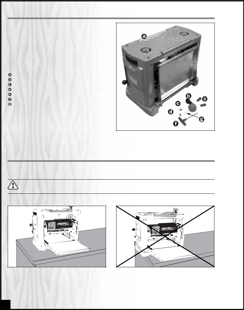
IDENTIFICATION OF MAIN PARTS AND COMPONENTS |
FRONT VIEW |
IN-FEED TABLE |
MOUNTING HOLES |
CIRCUIT BREAKER |
STOCK THICKNESS SCALE |
DEPTH OF CUT INDICATOR |
PRESET DEPTH GAUGE |
ON/OFF SWITCH |
RETURN ROLLER |
CUTTERHEAD LOCKING HANDLE |
SPEED SELECTION HANDLE |
HEIGHT ADJUSTMENT HANDLE |
REAR VIEW |
OUT-FEED TABLE |
TOOL TRAY |
KNIFE SETTING MAGNETS |
T-HANDLE WRENCH |
CHIP DEFLECTOR |
POWER CORD |
POWER CORD STORAGE HOOKS |
RETURN ROLLER |
LIFTING HANDLE |
5 |
UNPACKING & SET UP
Carefully unpack and remove the planer and its components from the box and check for damaged or missing items as per the list of contents below.
NOTE: Please report any damaged or missing items to your
General International distributor immediately.
LIST OF CONTENTS
QTY
PLANER . . . . . . . . . . . . . . . . . . . . . . . . . . . . . . . . . . . . .1
ADJUSTMENT HANDLE . . . . . . . . . . . . . . . . . . . . . . . . .1
FLAT WASHER . . . . . . . . . . . . . . . . . . . . . . . . . . . . . . . .1
PAN HEAD BOLT . . . . . . . . . . . . . . . . . . . . . . . . . . . . . .1
KNIFE SETTING MAGNETS . . . . . . . . . . . . . . . . . . . . . .2
T-HANDLE WRENCH . . . . . . . . . . . . . . . . . . . . . . . . . . .1
POINTER . . . . . . . . . . . . . . . . . . . . . . . . . . . . . . . . . . . .1
ASSEMBLY INSTRUCTIONS
For your convenience this planer is shipped from the factory partially assembled and requires only minimal assembly and set up before being put into service.
BEFORE STARTING THE INSTALLATION AND ASSEMBLY, MAKE SURE THAT THE POWER SWITCH IS IN THE “OFF” POSITION AND THAT THE POWER CORD IS UNPLUGGED. DO NOT PLUG IN OR TURN ON THE PLANER UNTIL YOU HAVE COMPLETED THE INSTALLATION AND ASSEMBLY STEPS DESCRIBED IN THIS SECTION OF THE MANUAL.
The unit should be installed on a flat, level, sturdy and stable surface, able to support the weight of the machine and the workpiece with ease.
Never install or operate the planer over the edge of a table, workbench or other mounting surface.
6
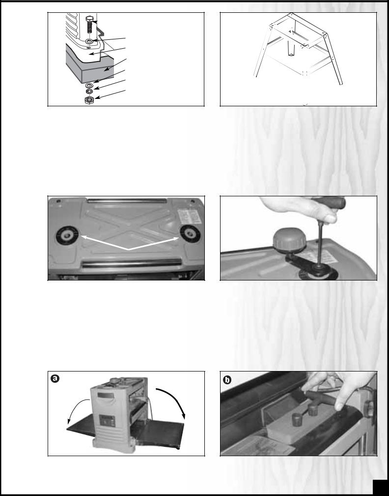
 HEX. HEAD BOLT
FLAT WASHER
PLANER
WORKBENCH OR STAND
FLAT WASHER
LOCK WASHER
HEX. NUT
If a permanent shop placement or installation is practical, consider using the mounting holes and drilling matching through holes in your workbench or mounting surface to bolt the planer in place (hardware not included) on your workbench.
If you prefer an optional steel stand (item #30-015) is available from your local General International dealer.
ATTACH THE DEPTH OF CUT ADJUSTMENT HANDLE
To accommodate the users personal preference or work habits the adjustment handle can be installed on either side of the top of the planer.
STOW THE KNIFE SETTING MAGNETS AND T-HANDLE WRENCH
With the T-Handle wrench, use the supplied washer and pan head screw to attach the depth of cut adjustment handle as shown.
Fold down the in-feed and out-feed tables, , and stow the knife setting magnets and T-handle wrench in the holder at the rear of the machine as shown,
 .
.
7
BASIC ADJUSTMENTS AND CONTROLS
CONNECTING TO A POWER SOURCE
SWITCH OFF |
Once the assembly steps have been completed and the unit |
installed on a work surface such |
as a bench, stand or worktable, uncoil the power cord from |
. With the switch in the off po- |
sition, plug the power cord into an appropriate outlet. Refer |
entitled Electrical Requirements |
and make sure all requirements and grounding instructions |
planing operations have been |
completed unplug the unit from the power source and wrap |
onto the storage brackets for |
safe storage, . |
|
ON/OFF POWER SWITCH
|
|
|
|
|
|
|
|
|
|
|
|
|
|
|
|
|
|
|
|
|
|
|
|
|
|
|
|
|
|
|
|
|
|
|
|
|
|
|
|
|
|
|
|
|
|
|
|
|
|
|
|
|
|
|
|
|
|
|
|
|
|
|
|
|
|
POWER ON |
POWER OFF |
||||
|
|
|
|
|
|
|
|
|
|
|
|
|
|
|
|
|
|
|
|
|
|
|
|
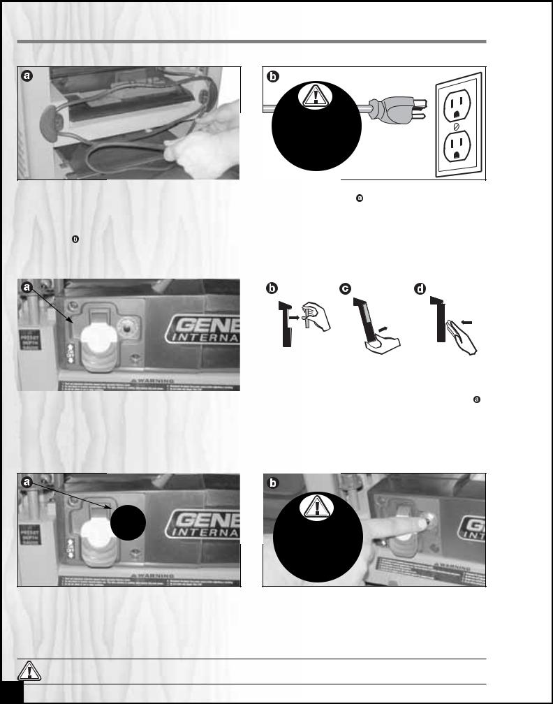
The planer is equipped with a rocker style ON/OFF switch located |
|
side of the cutter head, . |
|||||||||
To prevent unwanted or unauthorized start-up or usage, remove whenever the planer is not in use. To start the planer, insert the switch as shown, . To stop the planer, push down on the switch,
and store it in a safe place, , up on the lower portion of the
SURGE PROTECTION/CIRCUIT BREAKER
SWITCH OFF |
The unit is equipped with a circuit breaker located to the right of the power switch,  , to protect the motor from power surges or spikes in line voltage. In the event of a power surge, the circuit breaker will be automatically tripped thereby cutting off the power to the motor.
To reset the circuit breaker after it has been tripped; set the power switch to the “off” position and depress the reset button on the circuit breaker as shown, , then restart the machine.
TO AVOID UNEXPECTED OR UNINTENTIONAL START-UP BE CERTAIN THAT THE POWER SWITCH HAS BEEN SET TO THE OFF POSITION BEFORE RE-SETTING THE CIRCUIT BREAKER.
8
 Loading...