


 Heavy-duty precision cast iron ribbed table with miter gauge “t” slot.
 2 steel extension wings.
 Heavy-duty open steel stand and frame for greater stability.
 Large hand wheels quick and easy blade height and angle adjustment.
 Angle bracket for switch mounts to front fence rail.
 See-through blade guard with splitter and antikickback fingers.
 Forged one-piece precision machined arbor for minimal blade run out.
 Equipped with onboard storage mounts for wrenches, rip fence and miter gauge.
 Powerful 110/220 Volt - dual capacitor - 2 HP motor.
BLADE DIAMETER 10’’ (255 mm)
ARBOR DIAMETER 5⁄8” (16 mm) ARBOR TILT RANGE
0° TO 45° (RIGHT TILT)
DEPTH OF CUT, MAX AT 90° 3’’ (77 mm)
DEPTH OF CUT, MAX AT 45° 2 1⁄8’’ (54 mm)
RIP MAX. TO LEFT OF BLADE 12’’ (305 mm)
RIP MAX. TO RIGHT OF BLADE 30’’ (763 mm)
ARBOR SPEED 4200 RPM
TABLE SIZE
27’’ x 39 1⁄2” (686 x 1003 mm)
BASE DIMENSIONS (L X W) 21’’ x 26” (533 x 660 mm)
MOTOR
2 HP, 110/220 V, 15 A (PRE-WIRED 110 V)
WEIGHT
237 LBS (108 kg)
Revision 3 MARCH 05/07
© COPYRIGHT GENERAL INTERNATIONAL 03/2007

GENERAL® INTERNATIONAL
8360 Champ-d’Eau, Montreal (Quebec) Canada H1P 1Y3 Telephone (514) 326-1161 • Fax (514) 326-5555 • www.general.ca
THANK YOU for choosing this General International Star-Shop model 50-075 Contractor-style table saw. This saw has been carefully tested and inspected before shipment and if properly used and maintained, will provide you with years of reliable service. To ensure optimum performance and trouble-free operation, and to get the most from your investment, please take the time to read this manual before assembling, installing and operating the unit.
The manual’s purpose is to familiarize you with the safe operation, basic function, and features of this saw as well as the set-up, maintenance and identification of its parts and components. This manual is not intended as a substitute for formal woodworking instruction, nor to offer the user instruction in the craft of woodworking. If you are not sure about the safety of performing a certain operation or procedure, do not proceed until you can confirm, from knowledgeable and qualified sources, that it is safe to do so.
Once you’ve read through these instructions, keep this manual handy for future reference.
GENERAL ® INTERNATIONAL WARRANTY
All component parts of General® International machinery are carefully tested and inspected during all stages of production, and each machine is thoroughly inspected upon completion of assembly. Because of our commitment to quality and customer satisfaction, General® International agrees to repair or replace, within a period of 24 months from date of purchase, any genuine part or parts which, upon examination, prove to be defective in workmanship or material. In order to obtain this warranty, all defective parts must be returned freight pre-paid to General® International Mfg. Co., Ltd. Repairs attempted without our written authorization will void this warranty.
Disclaimer: The information and specifications in this manual pertain to the unit as it was supplied from the factory at the time of printing. Because we are committed to making constant improvements, General International reserves the right to make changes to components, parts or features of this unit as deemed necessary, without prior notice and without obligation to install any such changes on previously delivered units. Reasonable care is taken at the factory to ensure that the specifications and information in this manual corresponds with that of the unit with which it was supplied. However, special orders and “after factory”
modifications may render some or all information in this manual inapplicable to your machine. Further, as several generations of this model of saw and several versions of this manual may be in circulation, if you own an earlier or later version of this unit, this manual may not depict your machine exactly. If you have any doubts or questions contact your retailer or our support line with the model and serial number of your unit for clarification.

Rules for Safe Operation
To help ensure safe operation, please take a moment to learn the machine’s applications and limitations, as well as potential hazards. General® International, disclaims any real or implied warranty and holds itself harmless for any injury that may result from improper use of its equipment.
1.Do not operate the saw when tired, distracted, or under the effects of drugs, alcohol or any medication that impairs reflexes or alertness.
2.The working area should be well lit, clean and free of debris.
3.Keep children and visitors at a safe distance when the saw is in operation; do not permit them to operate the saw.
4.Childproof and tamper proof your shop and all machinery with locks, master electrical switches and switch keys, to prevent unauthorized or unsupervised use.
5.Stay alert! Give your work your undivided attention. Even a momentary distraction can lead to serious injury.
6.Fine particulate saw dust is a carcinogen that can be hazardous to health. Work in a well-ventilated area and whenever possible use a dust collector and wear eye, ear and respiratory protection devices.
7.Do not wear loose clothing, gloves, bracelets, necklaces and ornaments while saw is in operation.
8.Be sure that adjusting wrenches, tools, drinks and other clutter are removed from the machine and/or the table surface before commencing operation.
9.Keep hands well away from saw blade and all moving parts. Use a push stick to feed stock, and use a brush, not hands, to clear away chips and sawdust.
10.Be sure that saw blade is securely locked, and in proper cutting direction, before operation.
11.Use recommended-speed, saw blade and accessories for the working material.
12.Be sure the blade has gained full operating speed before beginning to cut.
13.Always use a clean, properly sharpened blade. Dirty or dull blades are unsafe and can lead to accidents.
14.Do not push or force stock into the cutting blade. The saw will perform better and more safely when working at the rate for which it was designed.
15.Use suitable support when cutting stock that does not have a flat surface. Always hold stock firmly against the fence when ripping, or against the miter gauge when cross-cutting.
16.To minimize risk of injury in the event of work piece kickback, never stand directly in-line with the blade or in the potential kickback path of the work piece.
17.Avoid working from awkward or off balance positions. Do not overreach during cutting operation; keep both feet on floor. Never lean over or reach over the blade and never pull the work piece over the blade from behind. Use outfeed support or have an assistant help when ripping long material.
18.Keep blade guards in place and in working order. If a guard must be removed for maintenance or cleaning, be sure it is properly reattached before using the tool again.
19.Never leave the machine running with the power on when not in operation.
20.If using a power feeder, stop the feeder before stopping the table saw.
21.Use of parts and accessories NOT recommended by General® International may result in equipment malfunction or risk of injury.
22.Never stand on machinery. Serious injury could result if the tool is tipped over or if blade is unintentionally contacted.
23.Always disconnect tool from power before servicing or changing accessories such as a saw blade, or before performing any maintenance, cleaning or adjustments, or if the machine will be left unattended.
24.Make sure that switch is in the “OFF” position before plugging in the power cord.
25.Make sure tool is properly grounded. If tool is equipped with a 3-prong plug it should be used with a three-pole receptacle. Never remove the third prong
10” DELUXE BUILDER’S TABLE SAW
50-075 (right tilt)
ASSEMBLY INSTRUCTIONS
|
|
|
|
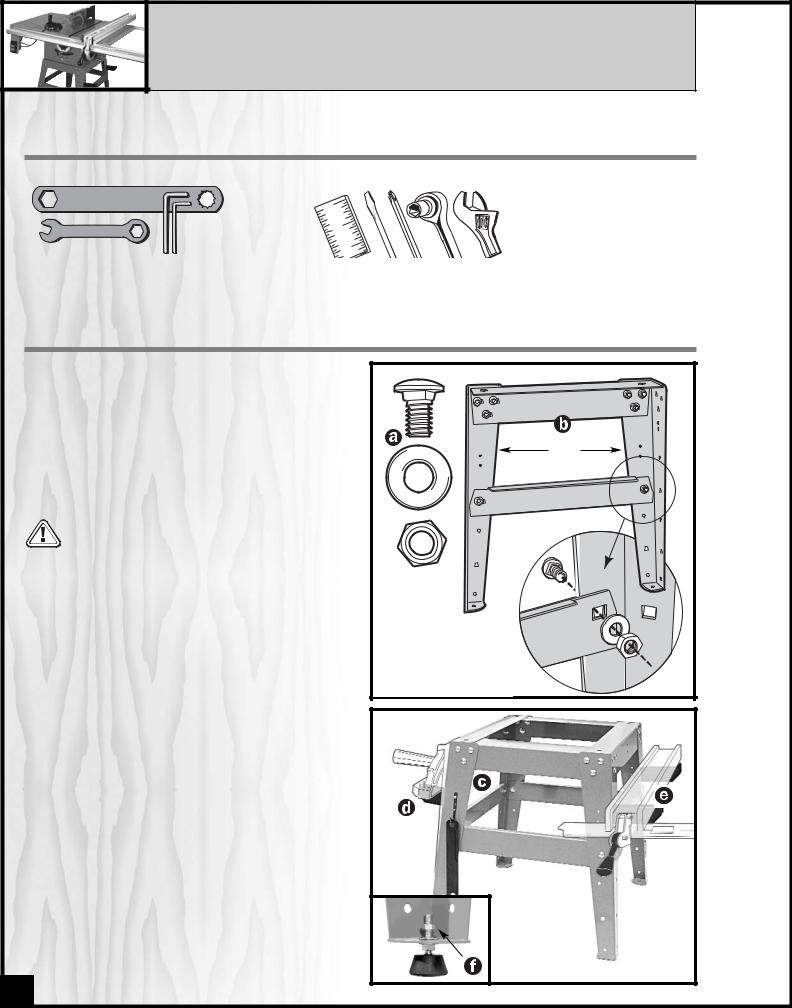
ASSEMBLY TOOLS PROVIDED |
ADDITIONAL TOOLS NEEDED |
||
• Arbor blade guard bracket wrench |
• Straightedge |
||
•12 mm combination wrench |
• Large slot and large Phillips screwdrivers |
||
• Two Allen wrenches |
• Socket wrench (recommended) and Adjustable wrench |
||
I. ASSEMBLE THE STAND
1.With the 32 carriage bolts, washers and hex nuts,
 , begin assembling one end of the saw stand by
attaching 1 short top shelf and 1 short tie bar to 2 legs,  .
.
Do not tighten hex nuts until all fasteners are attached. Then place the stand on a flat surface to  square it up and finally tighten all the nuts.
2.Assemble the opposite side of the stand the same way as described in step 1. Then use the 2 long top shelves and 2 long tie bars to join both assembled ends and complete the stand as shown in the photo below.
3.Fasten tool hook,  , to front (use one screw) or either
long top shelf (use both screws) of stand. Fasten brackets,  -
- (for stowing miter gauge and fence
when not in use) to long sides of stand.
4.Attach the 4 rubber feet to saw stand using 2 hex nuts
and 2 washers After fully assembled saw is placed in its final location, level the feet by loosening top nut,  ,
,
adjusting lower nut up or down on the screw stem as needed, then tightening down the top nut.
Short top shelf |
Legs |
Short tie bar |
(Be sure to attach all horizon- |
tal shelves and tie bars to the |
insides of stand legs.) |
If you will be using the mobile base (50-025), do not attach
rubber feet. Fasten the stand directly to the mobile base.
4

II. ATTACH THE DUST COLLECTION TRAY
The dust tray,  , is affixed to the saw stand top with the fasteners,
  , using the two holes in the stand top. Ideally, a dust collector hose would be clamped to the spout in the center of the tray. Otherwise, periodically turn the swivel tabs,
  , to remove and empty the tray well before the sawdust reaches the saw blade and motor.
III. FASTEN THE SAW TO THE STAND OR TO YOUR SHOP-MADE
BENCH
1. Place the saw onto the stand with its front end along one of the stand’s shorter ends and align the four holes in the stand’s top shelf with those in the saw base. Fasten saw to stand using the 4 hex head screws, 4 nuts and 8 washers supplied with the stand,  .
.
2.If the saw is to be used without our supplied stand, use the four holes on the bottom ledge of the saw
cabinet to fasten the saw to your supporting surface. Use the measurements shown at  to drill corresponding holes into your shop-built stand. (Or carefully position the saw upon your bench and with a pencil trace the four holes onto the stand surface. Drill the holes with a 7/16 bit.
A cutout hole must be provided in your wood |
Secure stand or bench to floor if during use there |
stand or bench for sawdust removal. |
is any tendency for the saw to tip over, slide or |
|
crawl. |
IV. ASSEMBLE THE RAISING AND TILTING HANDWHEELS AND
LOCK KNOBS
(back view)
1.Place the wheels in position over the raising and tilting screws being sure to engage the slots,  , in back of each wheel with the rollpins,
  , as shown
at right.
2.Screw on lock knobs  , to hold wheels in place, then attach silver handles,
  tightening them with
the supplied 12 mm combination wrench.
3.To use raising and tilting wheels, loosen lock nuts
(but not too much or rollpins will disengage from slots), turn wheels to desired position and retighten lock nuts. Do not operate saw with lock nuts untightened as the blade could move out of position.
5

V. REMOVE GREASE FROM THE SAW TOP
The protective coating on the saw table top and extension wings prevents rust from forming during shipping and storage. Remove it by rubbing with a rag dipped in kerosene, mineral spirits or paint thinner. (Dispose of potentially flammable solvent-soaked rags according to manufacturer’s safety recommendations.) A putty knife, held flat to avoid scratching the surface, may also be used to scrape off the coating followed by clean-up with solvent. Avoid rubbing the saw’s painted surfaces, as many solvent-based products will remove paint.
Suggestion: With a screw driver, push a solvent-saturated rag into the T-slots,  , to remove the grease so the miter gauge will slide freely.
VI. ASSEMBLE THE STEEL EXTENSION WINGS
Attach extension wings using the 6 hex head screws and lock washers, right. Make screws only finger tight at first. Use a straightedge to ensure that wing is level with table from front to back. Gently tap wing up or down, then tighten screws with the supplied combination wrench, leaving the center screw last to be tightened.
Be sure that extension wings are flush with front edge of table.
level here
flush here
VII. ASSEMBLE THE FRONT FENCE RAIL / GUIDE TUBE
Using 6 square head bolts (2 short bolts & 4 long). With their corresponding flat washers & hex. nuts,  , install the bolts to the front of the table as follows:
1.1 short bolt into each steel extension & 4 long bolts into the main tableas shown below, .
.
2.Do not tighten down the nuts, leave the square heads of the bolts protruding from the table,  .
.
3.Slide the upper slot of the rail onto the square head bolts,  , until all 6 bolts are in the slot and the left end of the rail is aligned with the edge of the extension wing,
  .
.
4.Tighten down the nuts to firmly secure the rail to the table.
6
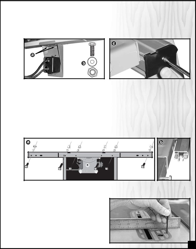
VIII. MOUNT THE SWITCH
Fit the head of the bolts into the slot in the underside of the rail.
Assemble the On/Off switch in the two holes in the switch bracket (leave the center hole free) on the left of the side of the rail,  , using the supplied hex nuts and washers,
  . Install the end caps at each end of the rail,
  .
.
IX. ATTACH THE REAR FENCE RAIL
Using 6 square head bolts (2 short bolts & 4 long). With their corresponding flat washers & hex. nuts, install the bolts to the rear of the table as follows:
1.1 short bolt into each steel extension & 4 long bolts into the main table, 
 .
.
2.Do not tighten down the nuts, leave the square heads of the bolts protruding from the table.
3.Slide the rail onto the bolts as shown,  , until all 6 bolts are in the slot and the left end of the rail is aligned with the edge of the extension wing.
4.Tighten down the nuts to firmly secure the rail to the table. Install the end caps at each end of the rail.
X. LEVEL THE TABLE INSERT
Place the insert into the table and use a straightedge to determine whether the insert is level with the table top. Turn each of the 4 adjusting screws with the supplied Allen wrench until done.
Suggestion: Start by adjusting one rear screw and its diagonal opposite in front, then tweak the remaining two screws.
Note: If the sawblade has already been installed, use the raising handwheel to lower the blade below the table surface before leveling the insert.
7

XI. INSTALL A SAW BLADE
Be sure the saw is disconnected from the power source whenever installing or removing a saw blade!
1.Remove the table insert by pulling with your finger in the hole, 
 . Use the supplied arbor wrench,
  ,
,
turning it counter-clockwise to remove the arbor nut and flange,  .
.
2.Install a saw blade (not supplied with the saw) so that the openings between the teeth face the front of the saw (the blade spins in the counter-clockwise direction).
3.Replace the flange and arbor nut. Wedge a board between the saw teeth at the back of the saw,  , so
, so
the blade won’t turn as you tighten the nut clockwise with the arbor wrench.
Remove a saw blade: wedge a block of wood between the teeth in front of the saw and turn the arbor wrench toward you, or counter-clockwise.
XII. INSTALL TAPE MEASURE ON FRONT RAIL
1.Raise the blade 1”- 2” above the table, move the fence to lightly touch the right side of the blade and lock the fence in place , 
 .
.
2.Using a pencil, make a light reference line on the top of the rail in-line with the screw hole for the fence pointer,  .
.
3.Remove the fence and stick the right hand (long) adhesive tape measure to the rail, roughly lining the zero point on the tape with your reference line on the rail,  .
.
4.To Install the left hand tape, repeat the same steps but to the left of the blade.
Install the pointer on the fence either to the left or left as needed. Do not fully tighten the pointer screw just yet. With the fence locked in place against the blade, line the reference line up on the pointer with the zero point on the tape and now tighten the pointer screw.
Note: when changing blades re-align the pointer with the zero point on the tape, to account for thinner or thicker blade widths.
8
 Loading...