


SETUP & OPERATION MANUAL
FEATURES
Adjustable spindle tension return spring. Built-in laser pointer.
Sturdy design with cast-iron head, base, and table.
High-quality bearings for smooth, vibration-free operation.
Simple hand lever controlled mechanical variable speed from 280 to 2100 rpm.
Digital spindle speed display. Industrial-quality 120 V motor. Chuck with key.
Easy to use see-through flip-up chuck guard included.
Crank-operated rack and pinion table heightadjustment.
SPECIFICATIONS
•Swing
15" (390 mm) - # 75-155 17" (430 mm) - # 75-165 20" (515 mm) - # 75-510
•Drilling capacity / Chuck size
3/4" (20 mm) / 5/8" (16 mm) - # 75-155
11/8" (28 mm) / 5/8" (16 mm) - # 75-165
11/4" (32 mm) / 3/4" (20 mm) - # 75-510
•Spindle travel
31/8" (80 mm) - # 75-155/165
43/4" (120 mm) - # 75-510
•Spindle distance to table / to base
293/8" (745 mm) / 48 1/2" (1230 mm) - # 75-155 29" (735 mm) / 48 5/8" (1235 mm) - # 75-165
273/4" (705 mm) / 46 7/8" (1190 mm) - # 75-510
•Table size
(Diameter) 12 3/8" (315 mm) - # 75-155
133/16" x 13 3/16" (335 x 335 mm) - # 75-165
183/4" x 16 3/4" (475 x 425 mm) - # 75-510
•Column diameter
23/4" (70 mm) - # 75-155
31/8" (80 mm) - # 75-165
3 5/8" (92 mm) - # 75-510
•Spindle speeds
(Variable speed) - 280 to 2100 rpm
•Spindle taper
MT 2 - # 75-155 / MT 3 - # 75-165/510
•Overall height
633/8" (1610 mm) - # 75-155
643/8" (1635 mm) - # 75-165 67" (1700 mm) - # 75-510
•Base size
17" x 10 1/2" (430 x 265 mm) - # 75-155
201/4" x 12" (515 x 303 mm) - # 75-165
235/8" x 15 3/4" (600 x 400 mm) - # 75-510
•Motor
1/2 HP, 120 V, 5A - # 75-155 3/4 HP, 120 V, 6,5A - # 75-165
1HP, 120 V, 10A - # 75-510
•Weight
136lbs (62 kg) - # 75-155
161 lbs (73 kg) - # 75-165
284 lbs (129 kg) - # 75-510
Version #1_Revision #4 - Mai 2016
© Copyright General International
15", 17" & 20" DRILL PRESSES
- VARIABLE SPEED
75-155
75-165
MODELS
#75-155
#75-165
#75-510
75-510

GENERAL® INTERNATIONAL
8360 Champ-d’Eau, Montreal (Quebec) Canada H1P 1Y3 Telephone (514) 326-1161 • Fax (514) 326-5555 • www.general.ca
THANK YOU for choosing this General® International model 75-155, 75-165 or 75-510 drill press. This drill press has been carefully tested and inspected before shipment and if properly used and maintained, will provide you with years of reliable service. For your safety, as well as to ensure optimum performance and trouble-free operation, and to get the most from your investment, please take the time to read this manual before assembling, installing and operating the unit.
The manual’s purpose is to familiarize you with the safe operation, basic function, and features of this drill press as well as the set-up, maintenance and identification of its parts and components.This manual is not intended as a substitute for formal woodworking/metalworking instruction, nor to offer the user instruction in the craft of woodworking/metalworking. If you are not sure about the safety of performing a certain operation or procedure, do not proceed until you can confirm, from knowledgeable and qualified sources, that it is safe to do so.
Once you’ve read through these instructions, keep this manual handy for future reference.
DISCLAIMER: The information and specifications in this manual pertain to the unit as it was supplied from the factory at the time of printing. Because we are committed to making constant improvements, General® International reserves the right to make changes to components, parts or features of this unit as deemed necessary, without prior notice and without obligation to install any such changes on previously delivered units. Reasonable care is taken at the factory to ensure that the specifications and information in this manual corresponds with that of the
unit with which it was supplied. However, special orders and “after factory” modifications may render some or all information in this manual inapplicable to your machine. Further, as several generations of this model of drill press and several versions of this manual may be in circulation, if you own an earlier or later version of this unit, this manual may not depict your unit exactly. If you have any doubts or questions contact your retailer or our support line with the model and serial number of your unit for clarification.

GENERAL® INTERNATIONAL WARRANTY
All component parts of General® International and Excalibur by General International® products are carefully inspected during all stages of production and each unit is thoroughly inspected upon completion of assembly.
Limited Lifetime Warranty
Because of our commitment to quality and customer satisfaction, General® International agrees to repair or replace any part or component which upon examination, proves to be defective in either workmanship or material to the original purchaser for the life of the tool. However, the Limited Lifetime Warranty does not cover any product used for professional or commercial production purposes nor for industrial or educational applications. Such cases are covered by our Standard 2-year Limited Warranty only. The Limited Lifetime Warranty is also subject to the “Conditions and Exceptions” as listed below.
Standard 2-Year Limited Warranty
All products not covered by our lifetime warranty including products used in commercial, industrial and educational applications are warranted for a period of 2 years (24 months) from the date of purchase. General® International agrees to repair or replace any part or component which upon examination, proves to be defective in either workmanship or material to the original purchaser during this 2-year warranty period, subject to the “conditions and exceptions” as listed below.
To file a Claim
To file a claim under our Standard 2-year Limited Warranty or under our Limited Lifetime Warranty, all defective parts, components or machinery must be returned freight or postage prepaid to General® International, or to a nearby distributor, repair center or other location designated by General® International. For further details call our service department at 1-888-949-1161 or your local distributor for assistance when filing your claim.
Along with the return of the product being claimed for warranty, a copy of the original proof of purchase and a“letter of claim”must be included (a warranty claim form can also be used and can be obtained, upon request, from General® International or an authorized distributor) clearly stating the model and serial number of the unit (if applicable) and including an explanation of the complaint or presumed defect in material or workmanship.
CONDITIONS AND EXCEPTIONS:
This coverage is extended to the original purchaser only. Prior warranty registration is not required but documented proof of purchase i.e. a copy of original sales invoice or receipt showing the date and location of the purchase as well as the purchase price paid, must be provided at the time of claim.
Warranty does not include failures, breakage or defects deemed after inspection by General® International to have been directly or indirectly caused by or resulting from; improper use, or lack of or improper maintenance, misuse or abuse, negligence, accidents, damage in handling or transport, or normal wear and tear of any generally considered consumable parts or components.
Repairs made without the written consent of General® International will void all warranty.

TABLE OF CONTENTS
Rules for safe operation..................................................................................................... |
5 |
Electrical requirements....................................................................................................... |
6 |
Identification of main parts and components................................................................... |
7 |
Unpacking.......................................................................................................................... |
8 |
Cleaning............................................................................................................................. |
9 |
Placement within the shop................................................................................................. |
9 |
Assembly instructions................................................................................................ |
10 - 16 |
Installing the column on the base.................................................................................................................. |
10 |
Installing the head stock on the column................................................................................................ |
10 - 11 |
Installing the table...................................................................................................................................... |
11 - 12 |
Installing the table (model 75-510 only)......................................................................................................... |
13 |
Installing the chuck guard............................................................................................................................... |
14 |
Installing the downfeed handles..................................................................................................................... |
14 |
Installing the chuck........................................................................................................................................... |
15 |
Removing the chuck......................................................................................................................................... |
16 |
Installing a drill bit............................................................................................................................................. |
16 |
Basic adjustments and controls....................................................................................... |
16 |
Connecting to a power source....................................................................................................................... |
16 |
On/Off power switch......................................................................................................................................... |
17 |
Adjusting the chuck guard height.................................................................................................................. |
17 |
Adjusting the depth stop.................................................................................................................................. |
17 |
Table swing adjustment.................................................................................................................................... |
18 |
Pivoting the table (model 75-155 & 75-165 only)........................................................................................... |
18 |
Adjusting table height...................................................................................................................................... |
18 |
Table tilt adjustment.......................................................................................................................................... |
19 |
Drill speed adjustment...................................................................................................................................... |
19 |
Guidelines for selecting speeds based on bit size and bit material.......................................................... |
19 |
Operating Instructions...................................................................................................... |
20 |
Checklist before starting................................................................................................................................... |
20 |
Drilling step-by-step........................................................................................................................................... |
20 |
Maintenance............................................................................................................. |
21 - 22 |
Belt replacement............................................................................................................................................... |
21 |
Lubrication......................................................................................................................................................... |
22 |
Recommended optional accessories |
.............................................................................. 22 |
Parts list & diagram................................................................................................... |
23 - 31 |
Contact information......................................................................................................... |
32 |

RULES FOR SAFE OPERATION
To help ensure safe operation, please take a moment to learn the machine’s applications and limitations, as well as potential hazards. General® International disclaims any real or implied warranty and hold itself harmless for any injury that may result from the improper use of it’s equipment.
1.Do not operate the drill press when tired, distracted, or under the effects of drugs, alcohol or any medication that impairs reflexes or alertness.
2.The work area should be well lit, clean and free of debris.
able work piece support if the work piece does not have a flat surface.
12.Do not push or force the bit into the stock. The drill will perform better and more safely when working at the rate feed for which it was designed.
3. |
Keep children and visitors at a safe distance when 13. |
Avoid working from awkward or off balance po- |
|
the drill press is in operation; do not permit them |
sitions. Do not overreach and keep both feet on |
|
to operate the drill press. |
floor. |
4.Childproof and tamper proof your shop and all14. Keep guards in place and in working order. If
machinery with locks, master electrical switches and switch keys, to prevent unauthorized or unsupervised use.
a guard must be removed for maintenance or cleaning be sure it is properly re-attached before using the tool again.
5.Stay alert! Give your work your undivided atten15. Never leave the machine unattended while it is
tion. Even a momentary distraction can lead to serious injury.
6.Fine particulate dust is a carcinogen that can be hazardous to health. Work in a well-ventilated area and whenever possible use a dust collector and wear eye, ear and respiratory protection devices.
running or with the power on.
16.Use of parts and accessories NOT recommended by GENERAL® INTERNATIONAL may result in equipment malfunction or risk of injury.
17.Never stand on machinery. Serious injury could result if the tool is tipped over or if the drill bit is unintentionally contacted.
7.Do not wear loose clothing, gloves, bracelets,
|
necklaces or other jewelry while the drill press is in |
18. Always disconnect the tool from the power |
|
operation. |
|
|
source before servicing or changing accesso- |
|
|
|
|
|
|
ries such as bits, or before performing any main- |
8. |
Be sure that adjusting wrenches, tools, drinks and |
tenance, cleaning, or if the machine will be left |
|
other clutter are removed from the machine and/ |
unattended. |
|
or the table surface before operating. |
|
9.Keep hands well away from the drill bit and all moving parts. Use a hold-down or clamp to secure the stock, and use a brush, not hands, to clear away chips and dust.
10.Be sure that the drill bit is securely installed in the chuck before operation.
11.Be sure the drill bit has gained full operating speed before beginning to drill. Always use a clean, properly sharpened bit. Dirty or dull bits are unsafe and can lead to accidents. Use suit-
19.Make sure that the switch is in the “OFF” position before plugging in the power cord.
20.Make sure the tool is properly grounded. If equipped with a 3-prong plug, it should be used with a three-pole receptacle. Never remove the third prong.
21.Do not use this drill press for other than its intended use. If used for other purposes, GENERAL® INTERNATIONAL disclaims any real implied warranty and holds itvself harmless for any injury, which may result from that use.
5

ELECTRICAL REQUIREMENTS
BEFORE CONNECTING THE MACHINE TO THE POWER SOURCE, VERIFY THAT THE VOLTAGE OF YOUR POWER SUPPLY CORRESPONDS WITH THE VOLTAGE SPECIFIED ON THE MOTOR I.D. NAMEPLATE. A POWER SOURCE WITH GREATER VOLTAGE THAN NEEDED CAN RESULT IN SERIOUS INJURY TO THE USER AS WELL AS DAMAGE TO THE MACHINE. IF IN DOUBT, CONTACT A QUALIFIED ELECTRICIAN BEFORE CONNECTING TO THE POWER SOURCE.
THIS TOOL IS FOR INDOOR USE ONLY. DO NOT EXPOSE TO RAIN OR USE IN WET OR DAMP LOCATIONS.
GROUNDING INSTRUCTIONS |
|
|
In the event of an electrical malfunction or short circuit, |
|
|
|
|
|
grounding reduces the risk of electric shock. The motor |
|
|
of this machine is wired for 120 V single phase opera- |
|
|
tion and is equipped with a 3-conductor cord and |
|
|
a 3-prong grounding plug A to fit a grounded type |
|
|
receptacle B. Do not remove the 3rd prong (ground- |
|
|
ing pin) to make it fit into an old 2-hole wall socket or |
A |
|
extension cord. If an adaptor plug is used C, it must be |
|
|
attached to the metal screw of the receptacle. |
|
|
Note: The use of an adaptor plug is illegal in some ar- |
|
|
eas. Check your local codes. If you have any doubts |
B |
C |
or if the supplied plug does not correspond to your |
||
electrical outlet, consult a qualified electrician be- |
|
|
fore proceeding. |
|
|
|
|
CIRCUIT CAPACITY
Make sure that the wires in your circuit are capable of handling the amperage draw from your machine, as well as any other machines that could be operating on the same circuit. If you are unsure, consult a qualified electrician. If the circuit breaker trips or the fuse blows regularly, your machine may be operating on a circuit that is close to its amperage draw capacity. However, if an unusual amperage draw does not exist and a power failure still occurs, contact a qualified technician or our service department.
EXTENSION CORDS
If you find it necessary to use an extension cord with your machine, use only 3-wire extension cords that have 3-prong grounding plug and a matching 3-pole receptacle that accepts the tool’s plug. Repair or replace a damaged extension cord or plug immediately.
Make sure the cord rating is suitable for the amperage listed on the motor I.D. plate. An undersized cord will cause a drop in line voltage resulting in loss of power and overheating. The accompanying chart shows the correct size extension cord to be used based on cord length and motor I.D. plate amp rating. If in doubt, use the next heavier gauge. The smaller the number, the heavier the gauge.
TABLE - MINIMUM GAUGE FOR CORD
EXTENSION CORD LENGTH
AMPERES |
50 feet |
100 feet |
200 feet |
300 feet |
< 5 |
18 |
16 |
16 |
14 |
6 to 10 |
18 |
16 |
14 |
12 |
10 to 12 |
16 |
16 |
14 |
12 |
12 to 16 |
14 |
12 |
*NR |
*NR |
|
|
|
|
|
*NR = Not Recommended
6

IDENTIFICATION OF MAIN PARTS AND COMPONENTS
I
H
 J
J
G 
F 
E
K
L
D
C  M
M
B
A
Model 75-165 shown
A. |
BASE |
H. |
SWITCH |
B. |
COLUMN |
I. |
PULLEY COVER |
C. |
TABLE PIVOT LOCK LEVER* |
J. |
MOTOR |
D. |
TABLE |
K. |
FEED HANDLE |
E. |
FLIP-UP CHUCK GUARD |
L. |
TABLE CRANK HANDLE |
F. |
LASER POINTER SWITCH |
M. RACK |
|
G. DIGITAL SPEED DISPLAY |
|
*Except on the model 75-510 |
|
|
|
|
|
7
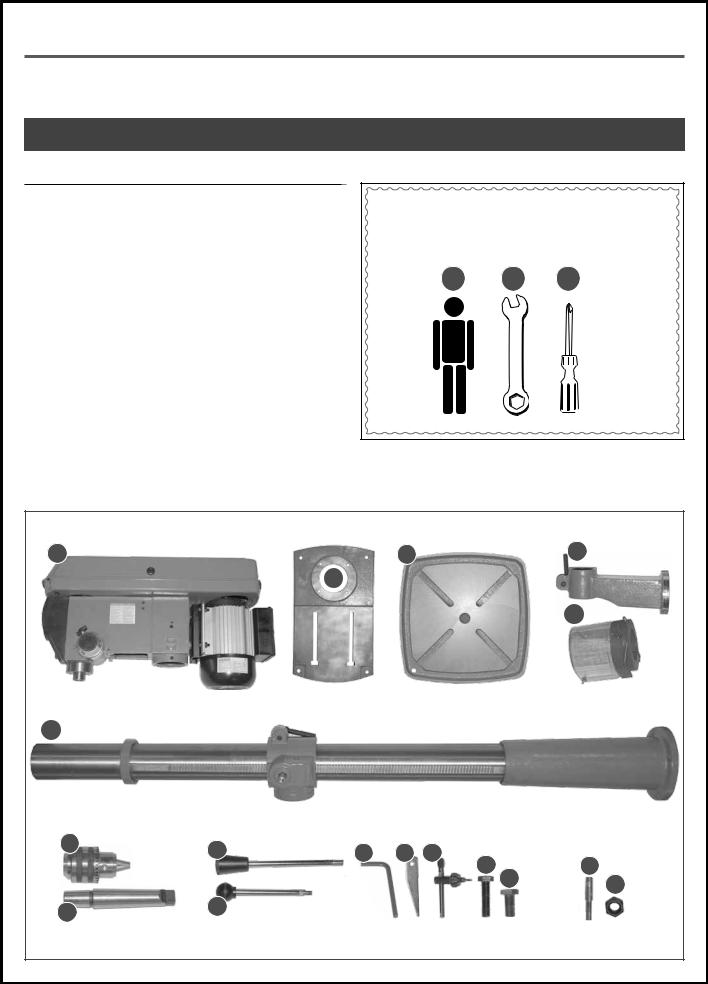
UNPACKING
Carefully unpack and remove the unit and its components from the box and check for missing or damaged items as per the list of contents below.
NOTE: PLEASE REPORT ANY DAMAGED OR MISSING ITEMS TO YOUR GENERAL® INTERNATIONAL DISTRIBUTOR IMMEDIATELY.
LIST |
OF CONTENTS |
QTY |
A. |
HEAD STOCK............................................................................ |
1 |
B. |
BASE.......................................................................................... |
1 |
C. |
TABLE......................................................................................... |
1 |
D. |
TABLE SUPPORT ARM................................................................ |
1 |
E. |
CHUCK GUARD........................................................................ |
1 |
F. |
COLUMN.................................................................................. |
1 |
G. |
CHUCK..................................................................................... |
1 |
H. |
ARBOR...................................................................................... |
1 |
I. |
DOWNFEED HANDLE................................................................ |
3 |
J. |
SPEED CONTROL LEVER........................................................... |
1 |
K. |
3, 4 & 5 MM ALLEN KEYS ......................................................... |
3 |
L. |
DRIFT KEY.................................................................................. |
1 |
M. |
CHUCK KEY.............................................................................. |
1 |
N. |
BASE BOLT................................................................................. |
4 |
O. |
ARM BOLT................................................................................. |
1 |
P. |
CENTERING PIN (75-510 ONLY)............................................... |
1 |
Q. |
BOLT (75-510 ONLY)................................................................. |
1 |
ADDITIONAL REQUIREMENTS FOR SET UP
A.EXTRA PERSON FOR HELP WITH LIFTING
B.9, 16 & 24 MM OPEN WRENCHES
C.PHILLIPS SCREWDRIVER
A B C
A |
C |
D * |
|
B |
|
|
|
E |
F
G |
I |
K |
L M |
|
75-510 ONLY |
|
|
|
|||
|
|
|
N |
O |
P |
|
|
|
|
Q |
|
|
|
|
|
|
|
H |
J |
|
|
|
|
|
|
|
|
|
|
|
|
|
|
|
|
*Except on the model 75-510
8

CLEANING
The protective coating on the machine prevents rust from forming during shipping and storage. Remove it by rubbing with a rag dipped in kerosene, mineral spirits or paint thinner. (Dispose of potentially flammable solvent-soaked rags according to manufacturer’s safety recommendations).
A putty knife, held flat to avoid scratching the surface, may also be used to scrape off the coating followed by clean-up with solvent. Avoid rubbing the machine's painted surfaces, as many solvent-based products will remove paint.
To prevent rust, apply a light coating of paste wax or use regular applications of any after-market surface protectant or rust inhibitor.
PLACEMENT WITHIN THE SHOP / SAFETY ZONE
THIS DRILL PRESS MODEL (1) 75-155, (2) 75-165 OR (3) 75-510 IS HEAVY. DO NOT OVER-EXERT. A HOIST OR FORKLIFT WITH STRAPS SHOULD BE USED TO LIFT THIS MACHINE. TO LIMIT THE RISK OF SERIOUS INJURY OR DAMAGE TO THE MACHINE, ANY EQUIPMENT USED TO LIFT THIS MACHINE SHOULD HAVE A RATED CAPACITY IN EXCESS OF THE MACHINE.
PLACEMENT WITHIN THE SHOP |
|
|
|
|
This machine should be installed and operated only |
(1) |
75-155 |
|
|
on a solid, flat and stable floor that is able to support |
(1) 23" |
|||
the weight of the machine 136 lbs (1), 161 lbs (2) or 284 |
(2) |
75-165 |
||
(2) 24" |
||||
lbs (3) and the operator. |
(3) |
75-510 |
(3) 28" |
|
Using the dimensions shown as a guideline, plan for |
|
|
|
|
placement within your shop that will allow the operator |
|
|
|
|
to work unencumbered and unobstructed by foot traf- |
|
|
|
|
fic (either passing shop visitors or other shop workers) |
|
|
|
|
or other tools or machinery. |
|
|
|
|
ESTABLISHING A SAFETY ZONE |
|
|
|
|
For shops with frequent visitors or multiple operators, |
|
|
(1) 63-3/8" |
|
it is advisable to establish a safety zone around shop |
(1) 12-3/8" |
|||
machinery. |
(2) 64-3/8" |
|||
(2) 13-3/16" |
(3) 67" |
|||
|
||||
A clearly defined “no-go” zone on the floor around |
(3) 18-3/4" |
|
||
|
|
|
||
each machine can help avoid accidents that could |
|
|
|
|
cause injury to either the operator or the shop visitor. |
|
|
|
|
It is advisable to take a few moments to either paint |
|
|
|
|
(using non-slip paint) or using tape, define on the floor |
|
|
|
|
the limits or perimeter of each machines safety zone. |
|
|
|
|
Take steps to ensure that all operators and shop visi- |
|
|
|
|
tors are aware that these areas are off limits whenever |
|
|
|
|
a machine is running for everyone but the individual |
|
|
|
|
operating the unit. |
|
|
|
|
|
|
|
Model 75-165 shown |
|
9

ASSEMBLY INSTRUCTIONS
BEFORE ASSEMBLING, MAKE SURE THAT THE SWITCH IS IN THE “OFF” POSITION AND THAT THE POWER CORD IS UNPLUGGED. DO NOT PLUG IN OR TURN ON THE MACHINE UNTIL YOU HAVE COMPLETED THE ASSEMBLY AND INSTALLATION STEPS DESCRIBED IN THIS SECTION OF THE MANUAL.
INSTALLING THE COLUMN ON THE BASE
1.Set the base on a flat and stable surface, and then install the column on the base.
A
2.Align the mounting holes in the column with the corresponding holes in the base.
3. Tighten the four bolts by hand A few turns. |
4. Then secure the bolts using a 16 mm wrench. |
INSTALLING THE HEAD STOCK ON THE COLUMN
THE HEAD STOCK IS HEAVY. DO NOT OVER-EXERT. THE HELP OF AN ASSISTANT WILL BE NEEDED FOR THE FOLLOWING STEP. DO NOT GRIP THE HEAD STOCK BY THE PULLEY COVER WHEN LIFTING.
|
|
|
|
|
|
|
|
|
|
|
|
1. Lift the head stock and place its opening above |
|
2. Slide the head stock opening onto the column. |
|
the column. |
|
|
|
10
 Loading...