


SETUP & OPERATION MANUAL
FEATURES
Large cast-iron extension wings.
Built-in mobile base with one-step lock-pedal.
Heavy-duty enclosed stand protects motor from dust and wood chips.
Positive gear design for quick and accurate table adjustments.
Heavy-duty cast-iron base, table, and head to eliminate vibration.
Built-in table rollers reduce friction.
Large handwheel quickly adjusts table height. Magnetic safety switch for added safety.
5” offset dust chute for efficient dust collection.
Convenient top mounted return rollers allow smooth stock handling for consecutive planing/ multiple passes.
Comes with knife setting gauge (30-300 only). Equipped with three drive belts.
SPECIFICATIONS
•Table size
25 9/16” x 20” (650 x 508 mm)
•Extension wing sizes
(2)15” x 21 1/4” (380 x 538 mm)
•Total surface of work table 55” x 20” (1437 x 506 mm)
•Maximum planing width 20” (508 mm)
•Maximum thickness of stock 8” (202 mm)
•Minimum thickness of stock 1/8” (3 mm)
•Minimum length of stock 6 3/4” (172 mm)
•Maximum depth of cut 1/8” (3 mm)
•Cutter head diameter 3 1/8” (80 mm)
•Cutter head speed 5000 rpm
•Feed rates
(2)16 & 20 fpm (4.87 & 6.1 mpm)
•Cuts per inch (not applicable for HC model) 78.13 at 16 fpm & 62.5 at 20 fpm
•Number of knives / Inserts 3 - 30-300 / 58 - 30-300HC
•Dust Outlet 5" (127 mm)
•Motor
5 HP, 220 V, 1 Ph, 23.2 A
•Weight
893 lbs (406 kg) - 30-300HC
860 lbs (390 kg) - 30-300
Version #2 / Revision #1 - November 2015
© Copyright General International
20” SINGLE SURFACE PLANER
MODELS *With helical cutter head
#30-300M1
#30-300HC M1* 

GENERAL® INTERNATIONAL
8360 Champ-d’Eau, Montreal (Quebec) Canada H1P 1Y3 Telephone (514) 326-1161 • Fax (514) 326-5555 • www.general.ca
THANK YOU for choosing this General® International model 30-300 or 30-300HC 20” single surface planer. This planer has been carefully tested and inspected before shipment and if properly used and maintained, will provide you with years of reliable service. For your safety, as well as to ensure optimum performance and trouble-free operation, and to get the most from your investment, please take the time to read this manual before assembling, installing and operating the unit.
The manual’s purpose is to familiarize you with the safe operation, basic function, and features of this planer as well as the set-up, maintenance and identification of its parts and components. This manual is not intended as a substitute for formal woodworking instruction, nor to offer the user instruction in the craft of woodworking. If you are not sure about the safety of performing a certain operation or procedure, do not proceed until you can confirm, from knowledgeable and qualified sources, that it is safe to do so.
Once you’ve read through these instructions, keep this manual handy for future reference.
DISCLAIMER: The information and specifications in this manual pertain to the unit as it was supplied from the factory at the time of printing. Because we are committed to making constant improvements, General® International reserves the right to make changes to components, parts or features of this unit as deemed necessary, without prior notice and without obligation to install any such changes on previously delivered units. Reasonable care is taken at the factory to ensure that the specifications and information in this
manual corresponds with that of the unit with which it was supplied. However, special orders and “after factory” modifications may render some or all information in this manual inapplicable to your machine. Further, as several generations of this model of planer and several versions of this manual may be in circulation, if you own an earlier or later version of this unit, this manual may not depict your unit exactly. If you have any doubts or questions contact your retailer or our support line with the model and serial number of your unit for clarification.

GENERAL® INTERNATIONAL WARRANTY
All component parts of General® International and Excalibur by General® International products are carefully inspected during all stages of production and each unit is thoroughly inspected upon completion of assembly.
Limited Lifetime Warranty
Because of our commitment to quality and customer satisfaction, General® International agrees to repair or replace any part or component which upon examination, proves to be defective in either workmanship or material to the original purchaser for the life of the tool. However, the Limited Lifetime Warranty does not cover any product used for professional or commercial production purposes nor for industrial or educational applications. Such cases are covered by our Standard 2-year Limited Warranty only. The Limited Lifetime Warranty is also subject to the “Conditions and Exceptions” as listed below.
Standard 2-Year Limited Warranty
All products not covered by our lifetime warranty including products used in commercial, industrial and educational applications are warranted for a period of 2 years (24 months) from the date of purchase. General® International agrees to repair or replace any part or component which upon examination, proves to be defective in either workmanship or material to the original purchaser during this 2-year warranty period, subject to the “conditions and exceptions” as listed below.
To file a Claim
To file a claim under our Standard 2-year Limited Warranty or under our Limited Lifetime Warranty, all defective parts, components or machinery must be returned freight or postage prepaid to General® International, or to a nearby distributor, repair center or other location designated by General® International. For further details call our service department at 1-888-949-1161 or your local distributor for assistance when filing your claim.
Along with the return of the product being claimed for warranty, a copy of the original proof of purchase and a“letter of claim”must be included (a warranty claim form can also be used and can be obtained, upon request, from General® International or an authorized distributor) clearly stating the model and serial number of the unit (if applicable) and including an explanation of the complaint or presumed defect in material or workmanship.
CONDITIONS AND EXCEPTIONS:
This coverage is extended to the original purchaser only. Prior warranty registration is not required but documented proof of purchase i.e. a copy of original sales invoice or receipt showing the date and location of the purchase as well as the purchase price paid, must be provided at the time of claim.
Warranty does not include failures, breakage or defects deemed after inspection by General® International to have been directly or indirectly caused by or resulting from; improper use, or lack of or improper maintenance, misuse or abuse, negligence, accidents, damage in handling or transport, or normal wear and tear of any generally considered consumable parts or components.
Repairs made without the written consent of General® International will void all warranty.

TABLE OF CONTENTS |
|
Rules for safe operation..................................................................................................... |
5 |
Electrical requirements....................................................................................................... |
6 |
Identification of main parts and components................................................................... |
7 |
Unpacking.......................................................................................................................... |
8 |
Clean-up............................................................................................................................. |
8 |
Placement within the shop................................................................................................. |
9 |
Assembly instructions.................................................................................................... |
9-11 |
Assembling the knife setting jig (for 30-300 only)............................................................................................ |
9 |
Installing the depth cut handwheel................................................................................................................ |
10 |
Intalling extension tables.................................................................................................................................. |
10 |
Installing the dust chute.................................................................................................................................... |
10 |
Connecting to a dust collector....................................................................................................................... |
11 |
Basic adjustments and controls.................................................................................. |
11-12 |
Connecting to a power source....................................................................................................................... |
11 |
On/Off magnetic power switch....................................................................................................................... |
11 |
Overload protection......................................................................................................................................... |
11 |
Deph of cut adjustment.................................................................................................................................... |
12 |
Feed speed control........................................................................................................................................... |
12 |
Operating Instructions................................................................................................. |
11-14 |
Basic principles of planing............................................................................................................................... |
11 |
Selecting boards suitable for planing............................................................................................................ |
12 |
Check list before starting.................................................................................................................................. |
12 |
Maintenance............................................................................................................... |
14-26 |
Adjusting the cutter head parallel to table.................................................................................................... |
14 |
Adjusting the infeed and outfeed rollers........................................................................................................ |
15 |
Adjusting the chipbreaker................................................................................................................................ |
15 |
Adjusting the table rollers................................................................................................................................. |
17 |
Adjusting the feed roller spring tension.......................................................................................................... |
17 |
Inspecting cutter head knives......................................................................................................................... |
18 |
Checking/setting the knives (30-300 only)..................................................................................................... |
18 |
Knife setting or replacement (30-300 only).................................................................................................... |
20 |
Helical cutter head insert reversal/replacement (model 30-300HC)......................................................... |
21 |
Periodic maintenance...................................................................................................................................... |
22 |
Replacing the gear box oil.............................................................................................................................. |
23 |
Cleaning the anti-kickback fingers................................................................................................................. |
24 |
Lubrication......................................................................................................................................................... |
24 |
Aligning the pulleys........................................................................................................................................... |
25 |
Adjusting belt tension........................................................................................................................................ |
25 |
Recommended optional accessories |
.............................................................................. 26 |
Parts list & diagrams................................................................................................... |
27-32 |
Contact information......................................................................................................... |
34 |

RULES FOR SAFE OPERATION
To help ensure safe operation, please take a moment to learn the machine’s applications and limitations, as well as potential hazards. General® International disclaims any real or implied warranty and holds itself harmless for any injury that may result from the improper use of its equipment.
1.Do not operate this planer when tired, distracted, or under the effects of drugs, alcohol or any medication that impairs reflexes or alertness.
2.The work area should be well lit, clean and free of debris.
3.Keep children and visitors at a safe distance when the planer is in operation; do not permit them to operate the planer.
4.Childproof and tamper proof your shop and all machinery with locks, master electrical switches and switch keys, to prevent unauthorized or unsupervised use.
5.STAY ALERT! Give your work your undivided attention. Even a momentary distraction can lead to serious injury.
6.Fine particulate dust is a carcinogen that can be hazardous to health. Work in a well-ventilated area and whenever possible use a dust collector. Wear face, eye, ear, respiratory and body protection devices.
7.Do not wear loose clothing, gloves, bracelets, necklaces or other jewelry while the planer is in operation. Wear protective hair covering to contain long hair and wear non-slip footwear.
8.Be sure that adjusting wrenches, tools, drinks and other clutter are removed from the machine and/or the table surface before operating.
9.Keep hands well away from knives and all moving parts. Use a push stick to feed stock, and a brush, not hands, to clear away chips and dust.
10.Be sure that the knives are securely installed in the cutter head.
11.Always use clean, properly sharpened knives. Dirty or dull knives are unsafe and can lead to accidents.
12.Inspect stock and remove all foreign objects before planing. Make sure that any stock you plane is clean and free of any dirt, nails, staples, tiny rocks or any other foreign objects that may damage the planer knives. Only process natural solid wood boards. Never plane MDF, particle board, plywood, laminates or other synthetic materials.
13.Do not push or force stock into the cutter head. The planer will perform better and safer when working at the rate for which it was designed.
14.Kickback is when the workpiece is ejected at high speeds by the force of the cutter head. To minimize the risk of injury from kickback, use proper feeding technique and stand to one side, out of the path of a potential kickback.
15.Select appropriate feed speed for the stock being planed: high speed for softwood and slow for hardwoods.
16.Place stock firmly against the table and use suitable in-feed and out-feed support if stock is too long.
17.Keep guards in place and in working order. If a guard must be removed for maintenance or cleaning make sure it is properly attached before using the machine again.
18.Use of parts and accessories NOT recommended by General® International may result in equipment malfunction or risk of injury.
19.Never stand or lean on machinery. Serious injury could result if the tool is tipped over or if the cutting tool is unintentionally contacted.
20.Always disconnect the tool from the power source before servicing or changing accessories such as knives, or before performing any maintenance or cleaning, or if the machine will be left unattended.
21.Make sure that the switch is in the “OFF” position before plugging in the power cord.
22.Make sure the tool is properly grounded. If equipped with a 3-prong plug it should be used with a threepole receptacle. Never remove the third prong.
23.Do not use this planer for any purpose other than its intended use. If used for other purposes,
General® International disclaims any real or implied warrantyand holds itself harmless for any injury, which may result from that use.
5

ELECTRICAL REQUIREMENTS
BEFORE CONNECTING THE MACHINE TO THE POWER SOURCE, VERIFY THAT THE VOLTAGE OF YOUR POWER SUPPLY CORRESPONDS WITH THE VOLTAGE SPECIFIED ON THE MOTOR I.D. NAMEPLATE. A POWER SOURCE WITH GREATER VOLTAGE THAN NEEDED CAN RESULT IN SERIOUS INJURY TO THE USER AS WELL AS DAMAGE TO THE MACHINE. IF IN DOUBT, CONTACT A QUALIFIED ELECTRICIAN BEFORE CONNECTING TO THE POWER SOURCE.
THIS TOOL IS FOR INDOOR USE ONLY. DO NOT EXPOSE TO RAIN OR USE IN WET OR DAMP LOCATIONS.
ELECTRICAL CONNECTIONS |
|
|
A |
||
Both a manual circuit breaker (or similar device) as well |
||
|
||
as an electrical plug (similar to the one shown) are re- |
|
|
commended and SHOULD BE INSTALLED BY A QUALI- |
|
|
FIED ELECTRICIAN. |
C |
|
Use locally approved wire A that includes a separate |
||
|
||
grounding wire and a 3 prong grounding type plug B |
|
|
with a matching receptacle C. |
|
B
GROUNDING INSTRUCTIONS
In the event of an electrical malfunction or short circuit,
grounding reduces the risk of electric shock to the operator. The motor of this machine is wired for 220 V single phase operation.
As with many stationary industrial type machines, because each installation situation is unique, this machine is supplied without a power cord or plug.
The installation of an appropriate power cord and plug must be performed by a qualified electrician. The machine must be connected to an electrical source using a power cord that has a grounding wire, which must also be properly connected to the grounding prong on the plug. The outlet must be properly installed and grounded and all electrical connections must be made in accordance with all local codes and regulations.
CIRCUIT CAPACITY
Make sure that the wires in your circuit are capable of handling the amperage draw from your machine, as well as any other machines that could be operating on the same circuit. If you are unsure, consult a qualified electrician.
If the circuit breaker trips or the fuse blows regularly, your machine may be operating on a circuit that is close to its amperage draw capacity. However, if an unusual amperage draw does not exist and a power failure still occurs, contact a qualified technician or our service department.
EXTENSION CORDS
The use of an extension cord is not generally recommended for 220V equipment.If you find it necessary,use only 3-wire extension cords that have 3-prong grounding plug and a matching 3-pole receptacle that accepts the tool’s plug. Repair or replace a damaged extension cord or plug immediately.
Make sure the cord rating is suitable for the amperage listed on the motor I.D. plate. An undersized cord will cause a drop in line voltage resulting in loss of power and overheating. The accompanying chart shows the correct size extension cord to be used based on cord length and motor I.D. plate amp rating. If in doubt, use the next heavier gauge.
TABLE - MINIMUM GAUGE FOR CORD
EXTENSION CORD LENGTH
AMPERES |
50 feet |
100 feet |
200 feet |
300 feet |
|
|
|
|
|
< 5 |
18 |
16 |
16 |
14 |
6 to 10 |
18 |
16 |
14 |
12 |
10 to 12 |
16 |
16 |
14 |
12 |
12 to 16 |
14 |
12 |
*NR |
*NR |
*NR = Not Recommended
6

IDENTIFICATION OF MAIN PARTS AND COMPONENTS
F
G
E
H
D
I
C
 J B
J B 
 K L
K L
M
A
A.BUILT-IN MOBILE BASE WITH LOCK-PEDAL
B.FRONT EXTENSION WING
C.MAIN TABLE
D.HEAD ASSEMBLY
E.MAGNETIC SAFETY SWITCH
F.DUST OUTLET
G.RETURN ROLLERS
H.DEPTH OF CUT ADJUSTMENT HANDWHEEL
I.REAR EXTENSION WING
J.FEED SPEED ADJUSTMENT KNOB
K.STOCK THICKNESS SCALE
L.CUTTER HEAD LOCK KNOB
M.RETRACTABLE LIFTING BAR
7
UNPACKING
Carefully unpack and remove the unit and its components from its shipping container and check for missing or damaged items as per the list of contents below.
NOTE: PLEASE REPORT ANY DAMAGED OR MISSING ITEMS TO YOUR GENERAL® INTERNATIONAL DISTRIBUTOR IMMEDIATELY.
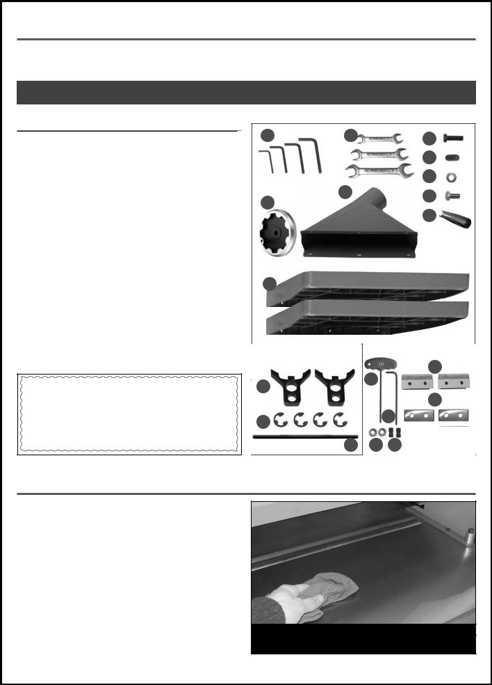
LIST |
OF CONTENTS |
QTY |
PLANER (NOT SHOWN)..................................................................... |
1 |
|
A. |
ALLEN KEY (3, 4, 5 & 6 MM)..................................................... |
1 |
B.COMBINATION WRENCH (8-10 MM, 12-14 MM & 17-19 MM)..1
C. |
BOLT.......................................................................................... |
6 |
D. |
SET SCREW................................................................................ |
6 |
E. |
WASHER (DUST CHUTE)............................................................ |
6 |
F. |
BOLT (DUST CHUTE).................................................................. |
6 |
G. |
HANDLE.................................................................................... |
1 |
H. |
HANDWHEEL............................................................................. |
1 |
I. |
DUST CHUTE.............................................................................. |
1 |
J. |
EXTENSION TABLE..................................................................... |
2 |
KNIFE SETTING JIG (30-300 M1) |
|
|
K. |
“C” CLIP.................................................................................... |
2 |
L. |
KNIFE SETTING JIG FOOT PAD.................................................. |
4 |
M. KNIFE SETTING JIG BAR............................................................ |
1 |
|
TOOLS/REPLACEMENT PARTS (30-300HC M1) |
|
|
N. |
5 MM “T” ALLEN KEY................................................................. |
1 |
O. |
5 MM ALLEN KEY...................................................................... |
1 |
P. |
NUT............................................................................................ |
2 |
Q. |
SCREW...................................................................................... |
2 |
R. |
KNIFE-HOLDER / CHIPBREAKER............................................... |
2 |
S. |
CARBIDE INSERT....................................................................... |
2 |
ADDITIONAL REQUIREMENTS FOR SET UP
A.PHILLIPS SCREWDRIVER
B.STRAIGHT EDGE
C.0.004”, 0.008”, 0.020” FEELER GAUGE
D.GAUGE BLOCK
CLEAN UP
A B C
D
E
I F
H
G
J
FOR 30-300 M1* |
FOR 30-300HC M1 |
|
|
R
N
L
S
K |
O |
|
M P Q
*Not included and not needed for 30-300HC
The protective coating on the planer tables prevents rust from forming during shipping and storage. Remove it by rubbing with a rag dipped in kerosene, mineral spirits or paint thinner. (Dispose of potentially flammable solvent soaked rags according to manufacturer’s safety recommendations.)
A putty knife, held flat to avoid scratching the surface, may also be used to scrape off the coating followed by clean-up with solvent. Avoid rubbing the planer’s painted surfaces, as many solvent-based products will remove paint.
To prevent rust, apply a light coating of paste wax or use regular applications of any after-market surface protectant or rust inhibitor.
TIP: WITH A SCREW DRIVER, PUSH A SOLVENT-SATURATED RAG INTO THE T-SLOTS TO REMOVE THE GREASE.
8
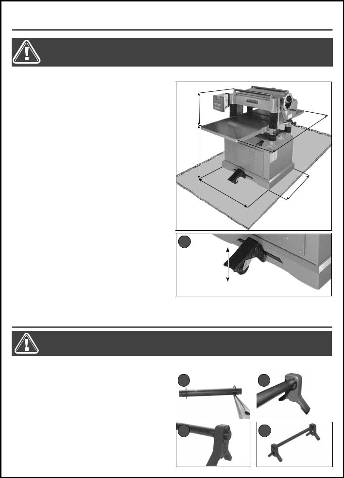
PLACEMENT WITHIN THE SHOP / SAFETY ZONE
THIS MODEL 30-300 PLANER IS HEAVY. DO NOT OVER-EXERT. A HOIST OR FORKLIFT WITH STRAPS SHOULD BE USED TO LIFT THIS MACHINE. TO LIMIT THE RISK OF SERIOUS INJURY OR DAMAGE TO THE MACHINE, ANY EQUIPMENT USED TO LIFT THIS MACHINE SHOULD HAVE A RATED CAPACITY IN EXCESS OF 860 LBS (390 KG).
PLACEMENT WITHIN THE SHOP |
|
|
This machine should be installed and operated only on |
|
|
a solid, flat and stable floor that is able to support the |
|
|
weight of the planer (860 lbs - 390 kg) and the operator. |
|
|
Using the dimensions shown as a guideline, plan for |
17" |
|
placement within your shop that will allow the operator |
||
|
||
to work unencumbered and unobstructed by foot traf- |
|
|
fic (either passing shop visitors or other shop workers) |
|
|
or other tools or machinery. |
" |
|
ESTABLISHING A SAFETY ZONE |
||
27 1/2" |
||
For shops with frequent visitors or multiple operators, |
||
|
||
it is advisable to establish a safety zone around shop |
|
|
machinery. A clearly defined “no-go” zone on the floor |
|
|
around each machine can help avoid accidents that |
|
|
could cause injury to either the operator or the shop |
|
|
visitor. |
23 1/2" |
|
It is advisable to take a few moments to either paint |
||
|
||
(using non-slip paint) or using tape, define on the floor |
|
|
the limits or perimeter of each machines safety zone. |
|
|
Take steps to ensure that all operators and shop visi- |
|
|
tors are aware that these areas are off limits whenever |
|
|
a machine is running for everyone but the individual |
A |
|
operating the unit. |
Note: To move the machine, step on the foot pedal A and roll the machine to the desired location. Once the machine is in place, raise the pedal to retract the built-in wheels.
ASSEMBLY INSTRUCTIONS
BEFORE ASSEMBLING MAKE SURE THAT THE SWITCH IS IN THE “OFF” POSITION AND THAT THE POWER CORD IS UNPLUGGED. DO NOT PLUG IN OR TURN ON THE MACHINE UNTIL YOU HAVE COMPLETED THE ASSEMBLY AND INSTALLATION STEPS DESCRIBED IN THIS SECTION OF THE MANUAL.
ASSEMBLING THE KNIFE SETTING JIG* |
|
|
|
|
1. |
Using a pair of pliers, push a “C” clip into the inner |
|
|
|
B |
|
C |
||
|
grooves on each end of the knife setting jig rod as |
|
||
|
shown B. |
|
|
|
2. |
Slide one foot onto one end of the rod as shown C. |
|
|
|
3. |
Secure the foot on the rod by pushing a “C” clip |
|
|
|
|
into the outer groove in the rod as shown D. |
|
|
|
4. |
Repeat step 2 and 3 to install the other foot as |
|
|
|
D |
|
E |
||
|
shown E. Set the jig aside for use whenever knife |
|
||
|
settings need to be verified or adjusted. |
|
|
|
*Not included and not needed for 30-300HC
9

BEFORE ASSEMBLING, MAKE SURE THAT THE SWITCH IS IN THE “OFF” POSITION AND THAT THE POWER CORD IS UNPLUGGED. DO NOT PLUG IN OR TURN ON THE MACHINE UNTIL YOU HAVE COMPLETED THE ASSEMBLY AND INSTALLATION STEPS DESCRIBED IN THIS SECTION OF THE MANUAL.
INSTALLING THE DEPTH OF CUT ADJUSTMENT HANDWHEEL
1.Remove the protective tape from the handwheel 2. Remove the nut and the flat washer from the shaft. shaft.
3.Install the handwheel onto the shaft by aligning its 4. Screw the handle into the handwheel, then secure
mounting hole with the key installed in the shaft and secure the handwheel by retightening the nut with the washer using a 19 mm wrench.
it using a 14 mm wrench.
INSTALLING THE EXTENSION TABLES
A
 B
B 
1.Install leveling screws B into the extension tables with 3. Use a straight edge approximately four feet long to
the a 3 mm Allen key so that they are flush with the surface that faces the machine.
2.Attach the table extensions to the machine using three hex head bolts A using the 12 mm wrench.
Note: This step requires help from an assistant.
verify table level.
4.Using the bolts A and set screws B, adjust so that there is no space between the straight edge and the tables.
5.Tighten bolts A and repeat the same procedure for the other table extension.
10
BEFORE ASSEMBLING, MAKE SURE THAT THE SWITCH IS IN THE “OFF” POSITION AND THAT THE POWER CORD IS UNPLUGGED. DO NOT PLUG IN OR TURN ON THE MACHINE UNTIL YOU HAVE COMPLETED THE ASSEMBLY AND INSTALLATION STEPS DESCRIBED IN THIS SECTION OF THE MANUAL.
INSTALLING THE SWITCH ASSEMBLY
1.Remove the two cap screws installed on the left 2. Align the switch assembly mounting holes with
front side of the machine.
holes in the machine. Secure it in place using the the two cap screws with a 5 mm Allen key.
INSTALLING THE DUST CHUTE
1.Align the 3 dust chute mounting holes with the cor- 2. Screw 3 bolts with washers into the upper part of the
responding holes in the machine. |
|
dust chute by hand. |
|
|
|
|
|
|
3.Screw 3 bolts with washers into the lower part of the 4. Secure the dust chute to the machine by tightening
dust chute by hand. |
all 6 bolts with a 10 mm wrench. |
11
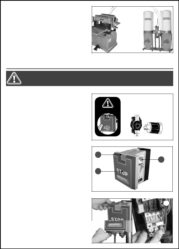
CONNECTING TO A DUST COLLECTOR
A dust port with a 5” opening is provided to accommodate connection to a dust collector (not included).
Be sure to use appropriate sized hose and fittings (not included). Check that all connections are sealed tightly to help minimize airborne dust. If you do not already own a dust collection system consider contacting your General® International distributor for information on our complete line of dust collection systems and accessories or visit our Web Site at www.general.ca.
BASIC ADJUSTMENTS & CONTROLS
TO REDUCE THE RISK OF SHOCK OR FIRE DO NOT OPERATE THE UNIT WITH A DAMAGED POWER CORD OR PLUG. REPLACE DAMAGED CORD OR PLUG IMMEDIATELY. TO AVOID UNINTENTIONAL START-UP, MAKE SURE THAT BOTH OF THE POWER SWITCHES ARE IN THE OFF POSITION BEFORE CONNECTING TO A POWER SOURCE.
CONNECTING TO A POWER SOURCE
Once the assembly steps have been completed, plug the power cord into an appropriate outlet.
Refer back to the section entitled “Electrical Requirements” and make sure all requirements and grounding instructions are followed.
When operations have been completed unplug the machine from the power source.
SWITCH OFF
STOP
TO AVOID UNEXPECTED OR UNINTENTIONAL START-UP, MAKE SURE THAT THE POWER SWITCH IS IN THE OFF POSITION BEFORE CONNECTING TO A POWER SOURCE.
ON/OFF MAGNETIC POWER SWITCH
This planer is equipped with a magnetic 2-step safety switch to prevent unintentional start-up and unauthorized use. The switch assembly is equipped with a “START” button A, an extra-large easy access stop panel B, and a lock-out key C.
To start the planer: Insert the lock-out key C and press on the “START” button A.
To stop the planer: Press on the “STOP” panel, B. Once the “STOP” panel has been pressed, the planer can only be re-started by pressing again on the “STOP” panel to release the green button, then by pressing on the button A.
OVERLOAD PROTECTION
The safety switch is equipped with an overload protection feature to prevent an electrical overload from damaging the motor. In the event of a spike in line voltage or amperage draw, the overload protector will automatically cut off power to the motor.
To reset the overload protection switch
1.Set the power switch to the OFF position, and disconnect the machine from the power source.
2.Unscrew the 2 screws on the control box front cover. Remove the cover and press the reset button D. Re-install the control box cover and reconnect the machine to the power source.
12
A
B
C
D
 Loading...