


 Steel frame and heavy duty base for greater stability.

 High quality conveyor belt for longer service life.

 Parallelism between the sanding drums and the conveyor belt is adjusted by convenient adjustment screw.
 Large hand wheel adjusts conveyor table height.
 Magnetic safety switch.
 Two (2) 4” dust outlets.
 Graduated depth scale in both inches and metric to indicate sanding thickness.
 Conveyor belt equipped with a safety switch with removable key.
 Dual v-belt driven sanding drums.
  Variable speed conveyor belt.
MAXIMUM SANDING WIDTH 24» (610 mm)
MAXIMUM SANDING THICKNESS 5” (127 mm)
MINIMUM SANDING THICKNESS 1⁄4” (6 mm)
MINIMUM SANDING LENGTH 5” (127 mm)
DRUM DIAMETER 5” (127 mm)
DRUM SPEED 1550 RPM
FEEDING SPEED
3 to 20 FPM (0.93 – 6.2 M/MIN) VARIABLE
BASE DIMENSIONS (L X W)
42 1/2” x 16 1/2” (1079.5 x 419 mm)
MAIN MOTOR
3 HP, 220 V, 1 Ph, 15 A
CONVEYOR MOTOR 1/6 HP
WEIGHT
570 LBS (259 kg)
REVISION 3 - APRIL 04/14
© COPYRIGHT GENERAL INTERNATIONAL

GENERAL® INTERNATIONAL
8360 Champ-d’Eau, Montreal (Quebec) Canada H1P 1Y3
Telephone (514) 326-1161 • Fax (514) 326-5555
www.general.ca
THANK YOU for choosing this General® International model 15-250 M1 24” Horizontal Double Drum Sander. This machine has been carefully tested and inspected before shipment and if properly used and maintained, will provide you with years of reliable service. To ensure optimum performance and trouble-free operation, and to get the most from your investment, please take the time to read this manual before assembling, installing and operating the unit.
The manual’s purpose is to familiarize you with the safe operation, basic function, and features of this horizontal double drum sander as well as the set-up, maintenance and identification of its parts and components. This manual is not intended as a substitute for formal woodworking instruction, nor to offer the user instruction in the craft of woodworking. If you are not sure about the safety of performing a certain operation or procedure, do not proceed until you can confirm, from knowledgeable and qualified sources, that it is safe to do so.
Once you’ve read through these instructions, keep this manual handy for future reference.
GENERAL ® INTERNATIONAL WARRANTY
All component parts of General® International machinery are carefully tested and inspected during all stages of production, and each machine is thoroughly inspected upon completion of assembly. Because of our commitment to quality and customer satisfaction, General® International agrees to repair or replace, within a period of 24 months from date of purchase, any genuine part or parts which, upon examination, prove to be defective in workmanship or material. In order to obtain this warranty, all defective parts must be returned freight pre-paid to General® International Mfg. Co., Ltd. Repairs attempted without our written authorization will void this warranty.
Disclaimer: The information and specifications in this manual pertain to the unit as it was supplied from the factory at the time of printing. Because we are committed to making constant improvements, General® International reserves the right to make changes to components, parts or features of this unit as deemed necessary, without prior notice and without obligation to install any such changes on previously delivered units. Reasonable care is taken at the factory to ensure that the specifications and information in this manual corresponds with that
of the unit with which it was supplied. However, special orders and “after factory” modifications may render some or all information in this manual inapplicable to your machine. Further, as several generations of this 24” horizontal double drum sander and several versions of this manual may be in circulation, if you own an earlier or later version of this unit, this manual may not depict your machine exactly. If you have any doubts or questions contact your retailer or our support line with the model and serial number of your unit for clarification.

Rules for Safe Operation
To help ensure safe operation, please take a moment to learn the machine’s applications and limitations, as well as potential hazards. General® International disclaims any real or implied warranty and hold itself harmless for any injury that may result from the improper use of it’s equipment.
1.Do not operate the sander when tired, distracted, or under the effects of drugs, alcohol or any medication that impairs reflexes or alertness.
2.The working area should be well lit, clean and free of debris.
3.Keep children and visitors at a safe distance when the sander is in operation; do not permit them to operate the sander.
4.Childproof and tamper proof your shop and all machinery with locks, master electrical switches and switch keys, to prevent unauthorized or unsupervised use.
5.Stay alert! Give your work your undivided attention. Even a momentary distraction can lead to serious injury.
6.Fine particulate dust is a carcinogen that can be hazardous to health. Work in a well-ventilated area and whenever possible use a dust collector and wear eye, ear and respiratory protection devices.
7.Do not wear loose clothing, gloves, bracelets, necklaces or other jewelry while the sander is in operation.
8.Be sure that adjusting wrenches, tools, drinks and other clutter are removed from the machine and/or the feed table surface before operating.
9.Keep hands well away from the sanding drums and all moving parts. Use a brush, not hands, to clear away sanding dust.
10.Be sure sanding belts are securely installed on the sanding drums.
11.Do not operate the sander if the sanding betls are damaged or badly worn.
12.Do not push or force the workpiece into the sander. The machine will perform better and more safely when working at the feed rate for which it was designed.
13.Avoid working from awkward or off balance positions. Do not overreach and keep both feet on floor.
14.Keep guards in place and in working order. If a guard must be removed for maintenance or cleaning, be sure it is properly re-attached before using the tool again.
15.Never leave the machine unattended while it is running or with the power on.
16.Use of parts and accessories NOT recommended by General® International may result in equipment malfunction or risk of injury.
17.Never stand on the machine. Serious injury could occur if the sander is tipped over or if the sanding drums are unintentionally contacted.
18.Always disconnect the tool from the power source before servicing, changing accessories or sanding belts, or before performing any maintenance or cleaning, or if the machine will be left unattended.
19.Make sure that switch is in "OFF" position before plugging in the power cord.
20.Make sure the tool is properly grounded. If equipped with a 3-prong plug it should be used with a three-pole receptacle. Never remove the third prong.
21.Do not use this sander for other than its intended use. If used for other purposes, General® International disclaims any real implied warranty and holds itself harmless for any injury, which may result from that use.
ELECTRICAL REQUIREMENTS
Before connecting the machine to the power source, verify that the voltage of your power supply corresponds with the voltage specified on the I.D. nameplate located on the back of the machine. A power source with greater voltage than needed can result in serious injury to the user as well as damage to the machine. If in doubt, contact a qualified electrician before connecting to the power source.
This tool is for indoor use only. Do not expose to rain or use in wet or damp locations.
GROUNDING INSTRUCTIONS |
|
In the event of an electrical malfunction or short circuit, grounding |
|
reduces the risk of electric shock to the operator. The motor of this |
|
machine is wired for 220V single phase operation and is equipped with |
|
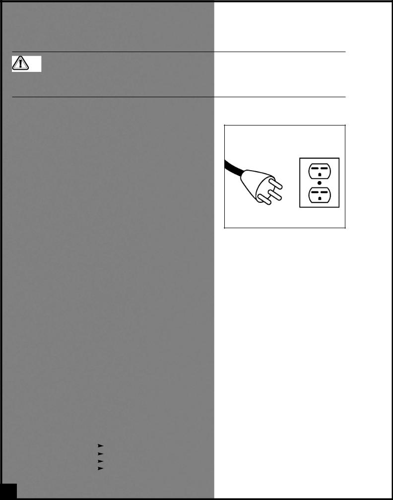
a 3-conductor cord and a 3-prong grounded plug to fit a matching |
|
grounded type receptacle. (Fig. 1). |
|
DO NOT MODIFY THE PLUG PROVIDED |
|
If it will not fit your receptacle, have the proper receptacle installed |
|
by a qualified electrician. |
|
Check with a qualified electrician or service person if you do not com- |
|
pletely understand these grounding instructions, or if you are not sure |
|
the tool is properly grounded. |
Fig. 1 |
|
CIRCUIT CAPACITY
Make sure that the wires in your circuit are capable of handling the amperage draw from your machine, as well as any other machines that could be operating on the same circuit. If you are unsure, consult a qualified electrician. If the circuit breaker trips or the fuse blows regularly, your machine may be operating on a circuit that is close to its amperage draw capacity. However, if an unusual amperage draw does not exist and a power failure still occurs, contact a qualified technician or our service department.
EXTENSION CORDS
The use of an extension cord is not generally recommended for 220V. If you find it necessary, use only 3-wire extension cords that have 3-prong grounding plug and a matching 3-pole receptacle that accepts the tool’s plug. Repair or replace a damaged extension cord or plug immediately.
If you find it necessary to use an extension cord with your machine make sure the cord rating is suitable for the amperage listed on the motor I.D. plate. An undersized cord will cause a drop in line voltage resulting in loss of power and overheating. The accompanying chart shows the correct size extension cord to be used based on cord length and motor I.D. plate amp rating. If in doubt, use the next heavier gauge. The smaller the number, the heavier the gauge.
|
|
|
|
TABLE - MINIMUM GAUGE FOR CORD |
|
|
||
|
|
|
|
|
|
|
|
|
AMPERE |
VOLTS |
|
TOTAL LENGTH OF CORD IN FEET |
|
||||
RATING |
110 V |
25 ft. |
50 ft. |
|
100 ft. |
150 ft. |
||
MORE |
NOT |
220 V |
50 ft. |
100 ft. |
|
200 ft. |
300 ft. |
|
THAN |
MORE |
|
|
|
|
|
|
|
THAN |
|
|
|
AWG |
|
|
||
|
|
|
|
|
|
|||
0 |
6 |
|
|
18 |
16 |
|
16 |
14 |
|
|
|
||||||
6 |
10 |
|
|
18 |
16 |
|
14 |
12 |
|
|
|
||||||
10 |
12 |
|
|
16 |
16 |
|
14 |
12 |
|
|
|
||||||
12 |
16 |
|
|
14 |
12 |
|
- |
- |
|
|
|
||||||
4

24” HORIZONTAL DOUBLE DRUM SANDER
15-250 M1
IDENTIFICATION OF MAIN PARTS AND COMPONENTS
CRANK HANDLE
DUST OUTLETS
CONVEYOR MOTOR START/STOP SWITCH WITH SAFETY KEY
CONVEYOR BELT SPEED ADJUSTING KNOB
SANDING DRUM MOTOR MAGNETIC POWER SWITCH
CONVEYOR BELT
DEPTH GAUGE
CONVEYOR TABLE
5

UNPACKING
Carefully unpack and remove the unit and its components from its shipping container and check for missing or damaged items as per the list of contents below.
NOTE: Please report any damaged or missing items to your GENERAL® INTERNATIONAL distributor immediately.
LIST OF CONTENTS
Once the parts have been removed from the packaing, you should have the following items:
QTY
24” HORIZONTAL DOUBLE DRUM SANDER . . . . . . . . .1
HARDWARE BAG (from left to right)
— HANDLE KNOB . . . . . . . . . . . . . . . . . . . . . . . . . . . .1
— CRANK HANDLE . . . . . . . . . . . . . . . . . . . . . . . . . . .1
— 5 MM ALLEN KEY . . . . . . . . . . . . . . . . . . . . . . . . . .1
— 6 MM T-HANDLE ALLEN WRENCH . . . . . . . . . . . . .1
— 2 MM T-HANDLE ALLEN WRENCH . . . . . . . . . . . . .1
— 12-14 MM COMBINATION WRENCH . . . . . . . . . .1
ADDITIONAL REQUIREMENTS FOR SET UP
•Extra person for help with lifting
•Phillips Screwdriver
•10 mm open end wrench
•Utility knife
•Flat piece of wood or any similar non-cutting object
6
PLACEMENT WITHIN THE SHOP / ESTABLISHING A SAFETY ZONE
This sander is heavy. Do not over-exert. The help of an assistant will be needed for the following step.
To limit the risk of serious injury or damage to the machine, any equipment used to lift this machine (forklift or lifting hook) should have a rated capacity in excess of 570 lbs (259 kg).
PLACEMENT WITHIN THE SHOP
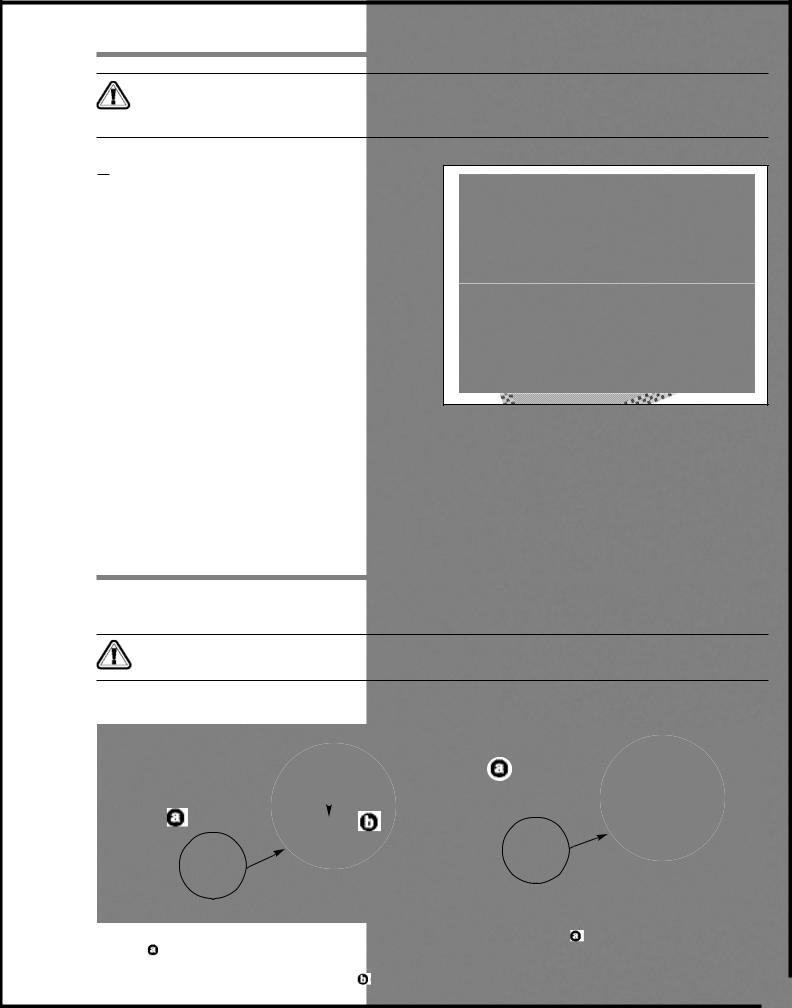
This machine should be installed and operated only on a solid, flat and stable floor that is able to support the weight of the sander (570 lbs/259 kg) and the operator. Using the dimensions shown in Fig. 2 as a guideline, plan for placement within your shop that will allow the operator to work unencumbered and unobstructed by foot traffic (either passing shop visitors or other shop workers) or other tools or machinery.
ESTABLISHING A SAFETY ZONE
Fig. 2
For shops with frequent visitors or multiple operators, it is
advisable to establish a Safety Zone around shop machinery. A clearly defined “no-go” zone on the floor around each machine can help avoid accidents that could cause injury to either the operator or the shop visitor. It is advisable to take a few moments to either paint (using non-slip paint) or using tape, define on the floor the limits or perimeter of each machines safety zone. Take steps to ensure that all operators and shop visitors are aware that these areas are off limits whenever a machine is running for everyone but the individual operating the unit.
ASSEMBLY INSTRUCTIONS
For your convenience this sander is shipped from the factory partially assembled and requires only minimal assembly and set up before being put into service.
Do not plug in or turn on the sander until you have completed the installation and assembly steps described in this section of the manual.
INSTALL THE CONVEYOR TABLE ELEVATION CRANK HANDLE
|
|
|
|
|
|
|
|
|
|
|
|
|
|
|
|
|
|
|
|
|
|
|
|
|
|
|
|
|
|
|
|
|
|
|
|
|
|
|
|
|
|
|
|
|
1. Install the conveyor table adjustment crank han- |
|
2. Screw the knob, , into the threaded hole in the |
||||||
dle, , on the shaft located on the top left end of |
|
crank handle. |
||||||
the sander. The slots in the crank handle must be |
|
|
|
|
|
|
||
aligned with the spring pin on the shaft, . |
|
|
|
|
|
|
||
|
|
|
|
7 |
||||
|
|
|
|
|
|
|
||
|
|
|
|
|
|
|
|
|
INSTALL THE CONTROL BOX
1.Loosen, but do not remove, the 2 hex bolts,  , installed on the top right hand corner of the machine.
1
2
2. Slide the control box onto the heads of the bolts.
3.Tighten the bolts to secure the control box in place, with a 10 mm open end wrench,  .
.
Do not plug in the power cord yet.
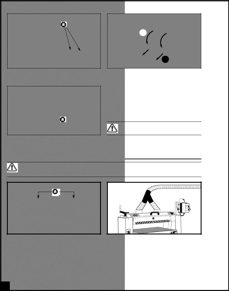
CONNECTING TO A DUST COLLECTOR
Do not operate this sander without an adequate dust collection system properly installed and running. Operating this sander without adequate dust collection can lead to equipment malfunction or dangerous situations for the operator or other individuals in the workshop.
The 24" horizontal double drum sander is equipped with two 4” diameter dust outlets,  , on top of the machine, allowing for the connection to a dust collector (not included).
Be sure to use appropriate sized hose and fittings (not included) and check that all connections are sealed tightly to help minimize airborne dust.
Note: Recommended dust collection CFM requirements for this sander is 1200 CFM (or 2HP dust collector).
If you do not already own a dust collection system consider contacting your General® International distributor for information on our complete line of dust collection systems and accessories or visit our Web Site at: www.general.ca.
8
BASIC FUNCTIONS OF THE UNIT
This 24” horizontal double drum sander is designed for surface sanding of wooden cabinet doors, flat wooden panels, wide glue-ups and other natural wood products only. This sander is not intended (and should not be used) to sand any material other than wood.
The main time saving feature of this unit is that it allows for sanding at 2 successive grits in one single pass. Use a rougher (lower numbered) grit sandpaper on the front drum and a finer (higher numbered) grit sandpaper on the rear drum.
Selecting the right combination of grits to use on each drum will depend on experience, personal preference and the finish requirements of the work. Keep in mind that normal sanding principals apply and that each successive grit further smoothens the surface and removes the scratch marks left by the previous grit. For ideal results never install a grit on the rear drum that is too high a jump up (no more than 2 grits higher) from the grit installed on the front drum. As an example, if a 100 grit paper is installed on the front drum, then either a 120 or 150 would be suitable for the rear drum.
BASIC PRINCIPLES OF SANDING
It is always preferable to remove less material per pass and take multiple passes. This can extend sanding belt life, place less strain on the motor and provide better workpiece finish quality.
Note: As with any other drum or belt sander, depending on the final finish quality you require, some final hand sanding may be required.
BASIC ADJUSTMENTS AND CONTROLS
CONNECTING TO A POWER SOURCE
SWITCHES
OFF
To avoid risk of shock or fire do not operate the unit with a damaged power cord or plug. Replace damaged cord or plug immediately.
To avoid unexpected or unintentional start-up, make sure that both of the power switches on the sander are in the OFF position before connecting to a power source.
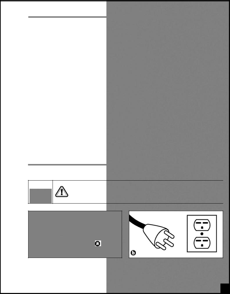
Once the assembly steps have been completed, uncoil the power cord,  , and plug it into an appropriate outlet,
 , (refer back to the section entitled "Electrical Requirements" and make sure all requirements and grounding instructions are followed).
9
ON/OFF POWER SWITCHES
This sander is equipped with 2 different ON/OFF power switches: one magnetic switch for the drums motor and one switch with a safety key for the conveyor motor.
DRUM MOTOR MAGNETIC SWITCH |
|
|
CONVEYOR MOTOR SWITCH WITH SAFETY KEY |
||||||||||
|
|
|
|
|
|
|
|
|
|
|
|
|
|
|
|
|
|
|
|
|
|
|
|
|
|
|
|
|
|
|
|
|
|
|
|
|
|
|
|
|
|
|
|
|
|
|
|
|
|
|
|
|
|
|
|
|
|
|
|
|
|
|
|
|
|
|
|
|
|
|
|
|
|
|
|
|
|
|
|
|
|
|
|
|
|
|
|
|
|
|
|
|
|
|
|
|
|
|
|
|
|
|
|
|
|
|
|
|
|
|
|
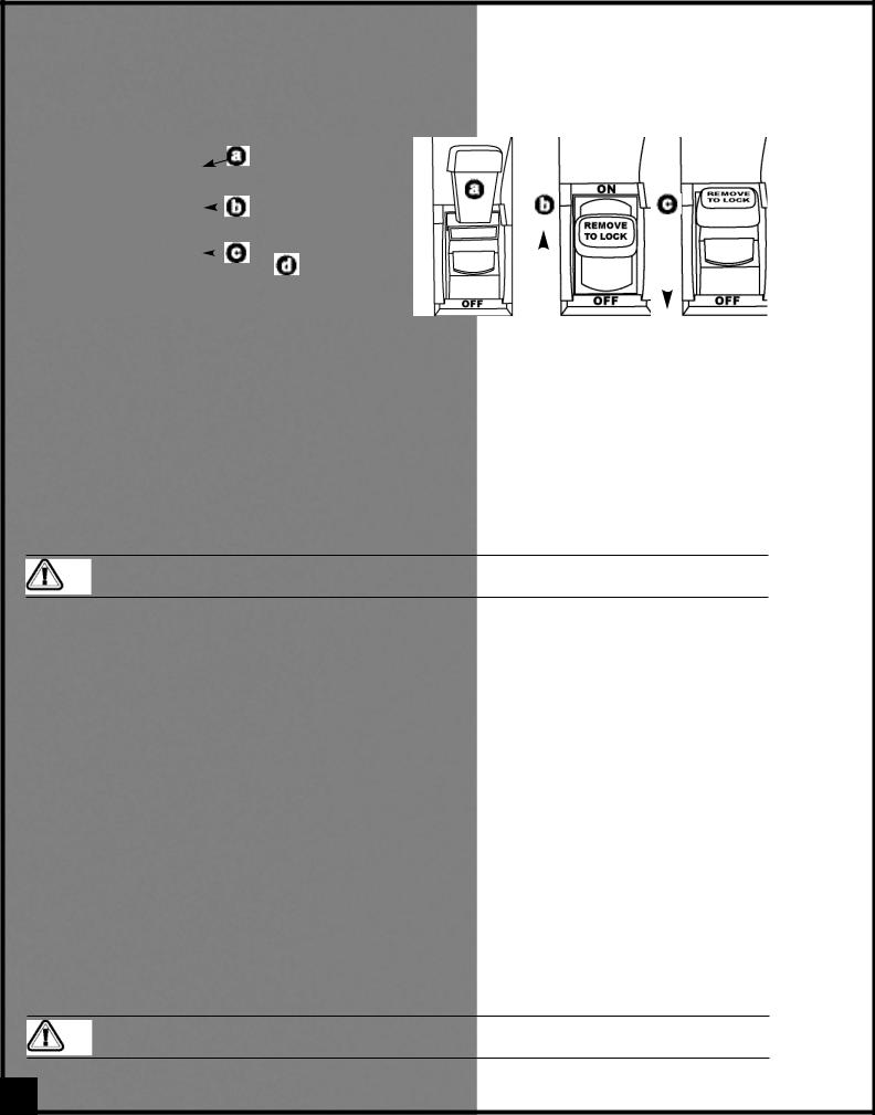
This model 15-250 M1 drum sander is equiped with a MAGNETIC SAFETY SWITCH , . located on the control box, designed to protect the unit and the user from power surges, power outages and unwanted or unintentional start-up.
The switch assembly is equipped with a GREEN “START” button, , and a RED spring loaded “STOP” button,
 .
.
Once the RED “STOP” button has been pressed, the machine can only be started by turning the BLACK inner part of the button to the right to release the stop button, .
.
SAFETY KEY* |
ON |
OFF |
* PREVENTS START-UP WHEN REMOVED
This model 15-250 M1 is also equiped with a simple ON/OFF switch for the conveyor motor, featuring a removable lock out safety key.
To start the conveyor belt, insert the safety key,  , and lift the switch up,
 . To stop the machine, pull the switch down,
  .
.
To prevent unauthorized use or unintentional start-up, remove the safety key and store it in a safe place whenever the sander is not in use.
Remove the switch key and store it in a safe place, out of the reach of children, whenever the sander is not in use.
OVERLOAD PROTECTION
The magnetic safety switch on this sander is equipped with an overload protection feature. To prevent an electrical overload from damaging the motor, in the event of a spike in line voltage or amperage draw, the internal overload protector will automatically be tripped, thereby cutting off power to the motor.
Note: The most common causes of such overloads are:
1.Overworking the motor by attempting to remove too much material in a single pass, thereby causing an increase in power consumption and a spike in amperage draw.
2.An electrical extension cord that is too long or not the correct gauge of wire, which can also cause an increase in amperage draw. If an electric extension cord must be used, follow the instructions and refer to the chart in the electrical requirements section at the beginning of this manual.
3.Overworked circuit caused by operating on a circuit that is close to its amperage draw capacity. Make sure the circuit being used is capable of handling the amperage draw from this machine as well as any other electrical devices operating on the same circuit. If you are unsure, consult a qualified electrician.
To reset the overload protection switch after it has been tripped proceed as follows:
To avoid unexpected or unintentional start-up be certain that both of the power switches have been set to the off position before re-setting the overload protection switch.
10
 Loading...