


90-140 M1

FEATURES
Cast-iron frame & precision-balanced alu-
minum wheels with replaceable rubber
tires.
Sturdy, easy to assemble, closed base steel
stand.
Precision aluminum miter gauge with han-
dle.
2 cutting speeds for excellent results in
either hard or soft woods.
Hinged door and easily accessible blade
tension knob, for fast blade changes or
adjustments.
Ball-bearing and carbon block blade
guide assembly.
Built-in blade cleaning brush keeps tires
free of dust and chips.
Safety lock-out switch with removable key
to prevent unauthorized use.
SPECIFICATIONS
WHEEL SIZE
13 7⁄8 ”(353 mm)
WHEEL SPEEDS (2)
470/820 RPM
MAXIMUM BLADE
WIDTH
3⁄4”(19 mm)
MINIMUM BLADE
WIDTH
1⁄4”(6 mm)
BLADE LENGTH
93 1⁄2”(2375 mm)
BLADE SPEEDS (2)
1630 & 2730 LIN. FPM (495/832 LIN. MPM)
T
ABLE SIZE
16”x 16”(406 x 406 mm)
T
ABLE TILT
0°- 45° (RIGHT) / 0°-10° (LEFT)
T
ABLE HEIGHT
42”(1067 mm)
MAXIMUM
WIDTH OF CUT
13 1⁄2”(343 mm)
MAXIMUM DEPTH OF CUT
6”(150 mm)
DUST COLLECTION POR
T
2 1⁄2”(63 mm)
B
ASE DIMENSIONS (L x W)
19 5⁄8”x 13”(498 x 330 mm)
MO
TOR
1 HP, 110 V, 1 PH, 10 A
WEIGHT
191 LBS (87 kg)
SETUP & OPERATION MANUAL
14” WOOD CUTTING BANDSAW
REVISION 1 - March 10/10
© Copyright General® International 03/2010
MODEL
#90-140 M1

THANK YOU
for choosing this General
®
International model 90-140 M1 14”
Wood Cutting Bandsaw. This bandsaw has been carefully tes ted and inspected before ship-
ment and if properly used and maintained, will provide you with years of reliable service. For
your safety,as well as to ensure optimum performance and trouble-free operation, and to get
the most from your investment, please take the time to read this manual before assembling,
installing and operating the unit.
The manual’s purpose is to familiarize you with the safe operation,basic function,and features
of this bandsaw as well as the set-up,maintenance and identification of its parts and compo-
nents. This manual is not intended as a substitute for formal woodworking instr uction, nor to
offer the user instruction in the craft of woodworking. If you are not sure about the safety of
performing a certain operation or procedure, do not proceed until you can confirm, from
knowledgeable and qualified sources,that it is safe to do so.
Once you’ve read through these instructions, keep this manual handy for future reference.
Disclaimer:
The information and specifications in this
manual pertain to the unit as it was supplied from the
factory at the time of printing. Because we are commit-
ted to making constant improvements, General
®
International reserves the right to make changes to
components, parts or features of this unit as deemed
necessary,without prior notice and without obligation to
install any such changes on previously delivered units.
Reasonable care is taken at the factory to ensure that
the specifications and information in this manual corres-
ponds with that of the unit with which it was supplied.
However, special orders and “after factory” modifica-
tions may render some or all information in this manual
inapplicable to your machine. Fur ther,as several gene-
rations of this model of bandsaw and several versions of
this manual may be in circulation, if you own an earlier
or later version of this unit, this manual may not depict
your machine exactly. If you have any doubts or ques-
tions contact your retailer or our support line with the
model and serial number of your unit for clarification.
GENERAL® INTERNATIONAL
8360 Champ-d’Eau, Montreal (Quebec) Canada H1P 1Y3
Telephone (514) 326-1161 • Fax (514) 326-5555 • www.general.ca

GENERAL
®
& GENERAL
®
INTERNATIONAL WARRANTY
All component parts of General®, General® International and Excalibur by General
International ® products are carefully inspected during all stages of production and each unit
is thoroughly inspected upon completion of assembly.
Limited Lifetime
Warranty
Because of our commitment to quality and customer satisfaction, General® and General®
International agree to repair or replace any part or component which upon examination,
proves to be defective in either workmanship or material to the original purchaser for the life
of the tool.
However, the Limited Lifetime Warranty does not cover any product used for profes-
sional or commercial production purposes nor for industrial or educational applications. Such
cases are covered b y our Standar d 2-year Limited Warranty only.The Limited Lifetime Warranty
is also subject to the “Conditions and Exceptions”as listed below.
Standard 2-Year Limited Warranty
All products not covered by our lifetime warranty including products used in commercial,
industrial and educational applications are warranted for a period of 2 years (24 months) from
the date of purchase. General® and General® Inter national agree to repair or replace any
part or component which upon examination, proves to be defective in either workmanship or
material to the original purchaser during this 2-year warranty period, subject to the “conditions
and exceptions”as listed below.
T
o file a Claim
To file a claim under our Standard 2-year Limited Warranty or under our Limited Lifetime
Warranty, all defective parts, components or machiner y must be returned freight or postage
prepaid to General® International, or to a nearby distributor, repair center or other location
designated by General® International. For further details call our service department at 1-888-
949-1161 or your local distributor for assistance when filing your claim.
Along with the return of the product being claimed for warranty, a copy of the original proof
of purchase and a “letter of claim”must be included (a w arranty claim form can also be used
and can be obtained,upon request, from General® International or an authorized distributor)
clearly stating the model and serial number of the unit (if applicable) and including an expla-
nation of the complaint or presumed defect in material or workmanship.
CONDITIONS AND EXCEPTIONS:
This coverage is extended to the original purchaser only. Prior warranty registration is not
required but documented proof of purchase i.e. a copy of original sales invoice or receipt
showing the date and location of the purchase as well as the purchase price paid, must be
provided at the time of claim.
Warranty does not include f ailures,breakage or defects deemed after inspection by General®
or General® International to have been directly or indirectly caused by or resulting from;
improper use, or lack of or improper maintenance, misuse or abuse, negligence, accidents,
damage in handling or transport, or nor mal wear and tear of any generally considered con-
sumable parts or components .
Repairs made without the written consent of General® Interna tional
l
will void all warranty.

TABLE OF CONTENTS
Rules for safe operation . . . . . . . . . . . . . . .5
Electrical requirements . . . . . . . . . . . . . . .6
Grounding instructions . . . . . . . . . . . . . . . . . . . . . . .6
Circuit capacity . . . . . . . . . . . . . . . . . . . . . . . . . . . . .6
Extension cords . . . . . . . . . . . . . . . . . . . . . . . . . . . . .6
Identification of main parts and
components . . . . . . . . . . . . . . . . . . . . . . . . . . . . . . . . . . . .
7
Unpacking . . . . . . . . . . . . . . . . . . . . . . . .8
List of contents . . . . . . . . . . . . . . . . . . . . . . . . . . . . . .8
Additional requirements for set up . . . . . . . . . . . . .8
Basic functions of the unit . . . . . . . . . . . . .9
Placement within the shop / Establishing a
safety zone . . . . . . . . . . . . . . . . . . . . . . . . . . . . . . . . . . . . .
9
Placement within the shop . . . . . . . . . . . . . . . . . . .9
Establishing a safety zone . . . . . . . . . . . . . . . . . . . .9
Clean up . . . . . . . . . . . . . . . . . . . . . . . . . .9
Assembly instructions . . . . . . . . . . . . . . .10
Assemble the base cabinet . . . . . . . . . . . . . . . . . .10
Install the bandsaw onto the base cabinet . . . .11
Attaching the dust port . . . . . . . . . . . . . . . . . . . . . .11
Attaching the table-tilt bracket . . . . . . . . . . . . . . .11
Attaching the table . . . . . . . . . . . . . . . . . . . . . . . . .12
Miter gauge . . . . . . . . . . . . . . . . . . . . . . . . . . . . . . .13
Power cord hooks . . . . . . . . . . . . . . . . . . . . . . . . . .13
Basic adjustments and controls . . . . . . . .13
Connecting to a power source . . . . . . . . . . . . . . .13
Power on/off switch with safety key . . . . . . . . . . . .13
Recommended adjustments . . . . . . . . . . .14
Adjusting the 90º table stop and re-aligning
the angle pointer . . . . . . . . . . . . . . . . . . . . . . . . . . . . . . . .14
Tilting the table . . . . . . . . . . . . . . . . . . . . . . . . . . . . .14
Removing/installing the blade . . . . . . . . . . . . . . .15
Blade clearance . . . . . . . . . . . . . . . . . . . . . . . . . . .15
To remove a blade . . . . . . . . . . . . . . . . . . . . . . . . .15
Blade selection . . . . . . . . . . . . . . . . . . . . . . . . . . . .16
To install a blade . . . . . . . . . . . . . . . . . . . . . . . . . . .16
Adjusting blade tension . . . . . . . . . . . . . . . . . . . . .17
Adjusting blade tracking . . . . . . . . . . . . . . . . . . . .18
Adjusting the blade guard for depth of cut . . . .19
Adjusting the upper guide blocks and
thrust bearing . . . . . . . . . . . . . . . . . . . . . . . . . . . . . .19
Positioning the lower guide blocks and
thrust bearing . . . . . . . . . . . . . . . . . . . . . . . . . . . . . .20
Changing speed settings . . . . . . . . . . . . . . . . . . . .21
Operating instructions . . . . . . . . . . . . . . .21
Checklist before starting . . . . . . . . . . . . . . . . . . . . .21
Connecting to a dust collector . . . . . . . . . . . . . . .22
Operations step-by-step . . . . . . . . . . . . . . . . . . . . .22
To stop the machine . . . . . . . . . . . . . . . . . . . . . . . .22
Using the miter gauge . . . . . . . . . . . . . . . . . . . . . .22
Cutting curves . . . . . . . . . . . . . . . . . . . . . . . . . . . . .23
Cutting circles . . . . . . . . . . . . . . . . . . . . . . . . . . . . .23
Periodic Maintenance & Lubrication . . . . . .23
Lubrification . . . . . . . . . . . . . . . . . . . . . . . . . . . . . . .23
Periodic maintenance . . . . . . . . . . . . . . . . . . . . . .23
Required Maintenance . . . . . . . . . . . . . . .24
Replacing the bandsaw blade . . . . . . . . . . . . . . .24
Replacing the upper and lower thrust bearing .24
Replacing the wheel tire . . . . . . . . . . . . . . . . . . . .25
Adjusting/replacing the lower wheel brush . . . .25
Replacing lower wheel motor belt . . . . . . . . . . . .25
Recommended optional accessoriess . . . .26
Parts list & diagrams . . . . . . . . . . . . . .27-33

1. Do not operate the bandsaw when tired, distracted
or under the effects of drugs, alcohol or any medi-
cation that impairs reflexes or alertness.
2. The working area should be well lit, clean and free
of debris.
3. Keep children and visitors at a safe distance when
the bandsaw is in operation; do not permit them to
operate the bandsaw.
4. Childproof and tamper proof your shop and all
machinery with locks, master electrical switches
and switch keys, to prevent unauthorized or unsu-
pervised use.
5. Stay alert! Give your work your undivided attention.
Even a momentary distraction can lead to serious
injury.
6. Fine particulate dust is a carcinogen that can be
hazardous to health. Work in a well-ventilated area
and whenever possible use a dust collector. Wear
face, eye, ear,respiratory and body protection de-
vices.
7. Do not wear loose clothing, gloves, bracelets,
necklaces or other jewelry while the bandsaw is in
operation.
8. Be sure that adjusting wrenches, tools , drinks and
other clutter are removed from the machine and/or
the table surface before operating.
9. Keep hands well away from the blade and all mo-
ving parts. Use a brush, not hands, to clear
away chips and dust.
10. Adjust and position upper and lower blade guides
before starting to cut. Upper blade guide should be
adjusted to approximately 1/8”above the material
to be cut.
11. Adjust blade tension and tracking before starting to
cut.
12. Saw teeth must point down toward the table.
13. Be sure that the blade has gained full operating
speed before starting to cut.
14. Always use a clean, properly sharpened blade.
Dirty or dull blades are unsafe and can lead to
accidents.
15. Use suitable workpiece support if the workpiece
does not have a flat surface.
16. Hold material firmly against the table.
17. Do not work on long stock without adequate sup-
port on the out feed end of the table.
18. If using a power feeder,stop the feeder before stop-
ping the bandsaw.
19. Do not push or force stock into the blade.The band-
saw will perform better and more safely when work-
ing at the rate for which it was designed.
20. Avoid working from awkward or off balance posi-
tions.Do not overreach and k eep both feet on f loor.
21. Keep guards in place and in working order. If a
guard must be removed for maintenance or clea-
ning be sure it is properly re-attached before using
the tool again.
22. Never leave the machine unattended while it is run-
ning or with the power on.
23. Use of parts and accessories NOT recommended
by
General® International may result in equip-
ment malfunction or risk of injury.
24. Never stand on machinery. Serious injury could re-
sult if the tool is tipped over or if the cutting tool is
unintentionally contacted.
25. Always disconnect the machine from the power
source before servicing or changing accessories
such as blades, or before performing any mainte-
nance or cleaning, or if the machine will be left un-
attended.
26. Make sure that the switch is in the “OFF”position be-
fore plugging in the power cord.
27. Make sure the tool is properly grounded.If equip-
ped with a 3-prong plug it should be used with a
three-pole receptacle. Never remove the third prong.
28. Do not use this bandsaw for other than its intended
use. If used for other purposes,
General® Interna-
tional disclaims any real implied warranty and holds
itself harmless for any injury,which may result from
that use.
Rules for Safe Operation
To help ensure safe operation, please take a moment to learn the machine’s applications and limita-
tions, as well as potential hazards. General® International disclaims any real or implied warranty and
hold itself harmless for any injury that may result from the improper use of it’s equipment.
5
6
ELECTRICAL REQUIREMENTS
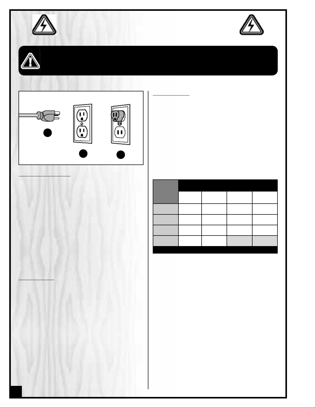
GROUNDING INSTRUCTIONS
In the event of an electrical malfunction or short circuit,
grounding reduces the risk of electric shock. The motor
of this machine is wired for 110V single phase operation
and is equipped with a 3-conductor cord and a 3-
prong grounding plug A to fit a grounded type recep-
tacle B.Do not remove the 3rd prong (grounding pin) to
make it fit into an old 2-hole wall socket or extension
cord. If an adaptor plug is used C, it must be attached
to the metal screw of the receptacle.
Note: The use of an adaptor plug is illegal in some
areas. Check your local codes. If you have any doubts
or if the supplied plug does not correspond to your elec-
trical outlet, consult a qualified eletrician before pro-
ceeding.
CIRCUIT CAPACITY
Make sure that the wires in your circuit are capable of
handling the amperage draw from your machine, as
well as any other machines that could be operating on
the same circuit. If you are unsure, consult a qualified
electrician. If the circuit breaker trips or the fuse blows
regularly, your machine may be operating on a circuit
that is close to its amperage draw capacity.However ,if
an unusual amperage draw does not exist and a
power failure still occurs,contact a qualified technician
or our service depar tment.
BEFORE CONNECTING THE MACHINE TO THE POWER SOURCE,VERIFY THAT THE VOLTAGE OF YOUR POWER SUPPLY CORRESPONDS
WITH THE VOLTAGE SPECIFIED ON THE MOTOR I.D. NAMEPLATE. A POWER SOURCE WITH GREATER VOLTAGE THAN NEEDED CAN
RESULT IN SERIOUS INJURY TO THE USER AS WELL AS DAMA GE T O THE MACHINE. IF IN DOUBT, CONTACT A QUALIFIED ELECTRICIAN
BEFORE CONNECTING TO THE POWER SOURCE.
THIS TOOL IS FOR INDOOR USE ONLY. DO NOT EXPOSE TO RAIN OR USE IN WET OR DAMP LOCATIONS.
EXTENSION CORDS
If you find it necessary to use an extension cord with your
machine, use only 3-wire extension cords that have 3-
prong grounding plug and a matching 3-pole recepta-
cle that accepts the tool’s plug. Repair or replace a
damaged extension cord or plug immediately.
Make sure the cord rating is suitable for the amperage
listed on the motor I.D. plate. An undersized cord will
cause a drop in line voltage resulting in loss of power
and overheating. The accompanying chart shows the
correct size extension cord to be used based on cord
length and motor I.D. plate amp rating. If in doubt, use
the next heavier gauge. The smaller the number, the
heavier the gauge.
AMPERES
(AMPS)
EXTENSION CORD LENGTH
25 FEET 50 FEET 100 FEET 150 FEET
< 5
18 16 16 14
6 TO 10 18 16 14 12
10 TO 12 16 16 14 14
12 TO 16 14 12
* NR * NR
* NR = Not Recommended
A
B
C
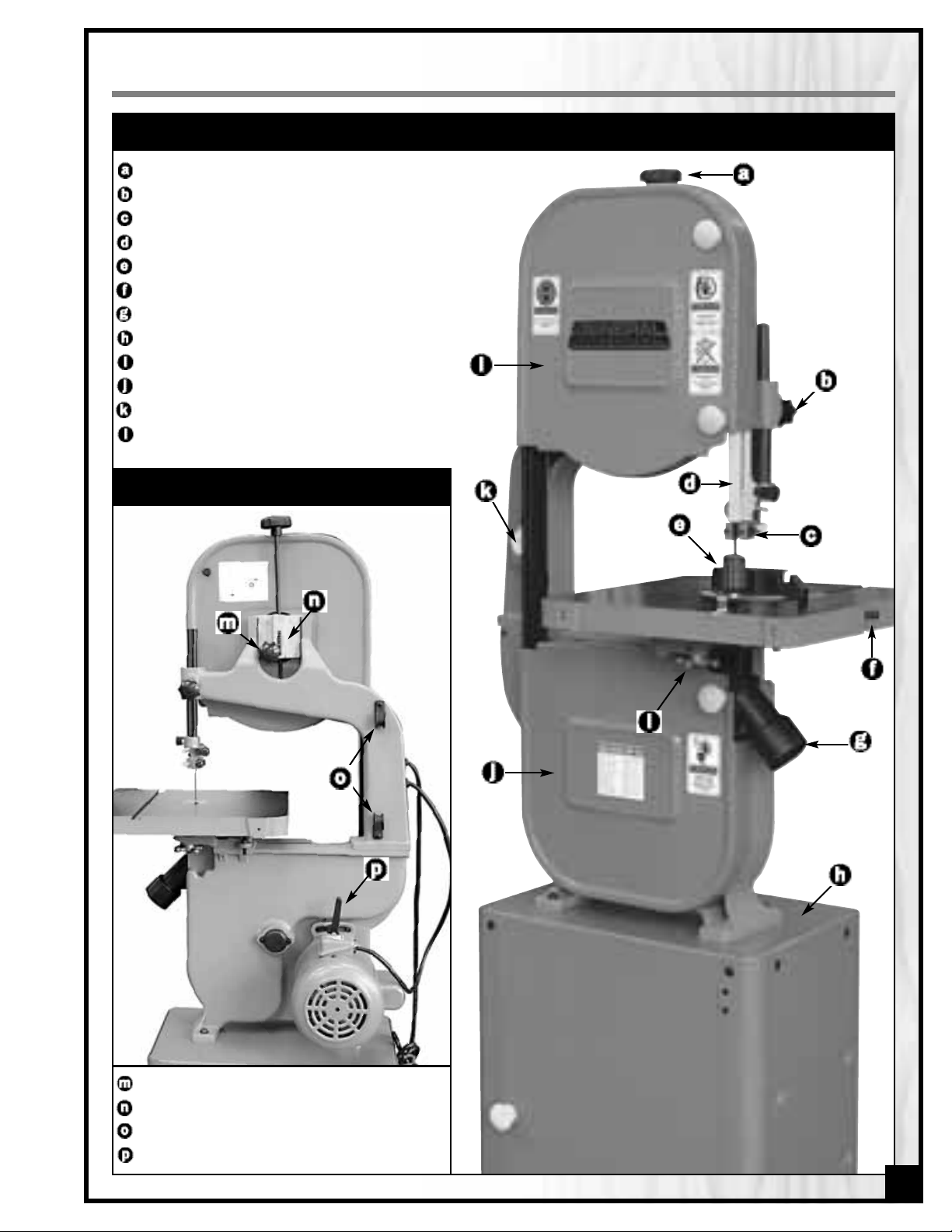
IDENTIFICATION OF MAIN PARTS AND COMPONENTS
FRONT VIEW
REAR VIEW
BLADE TENSION ADJUSTMENT KNOB
BLADE GUARD LOCK KNOB
UPPER BLADE GUIDE ASSEMBLY
BLADE GUARD
MITER GAUGE
TABLE ALIGNMENT PIN
DUST PORT
BASE CABINET
TABLE TILT LOCK KNOB
LOWER WHEEL COVER DOOR
ON/OFF SWITCH W/SAFETY KEY
UPPER WHEEL COVER DOOR
7
BLADE TRACKING ADJUSTMENT KNOB
BLADE TENSION INDICATOR
POWER CORD STORAGE BRACKETS
MOTOR PIVOT LOCKING LEVER
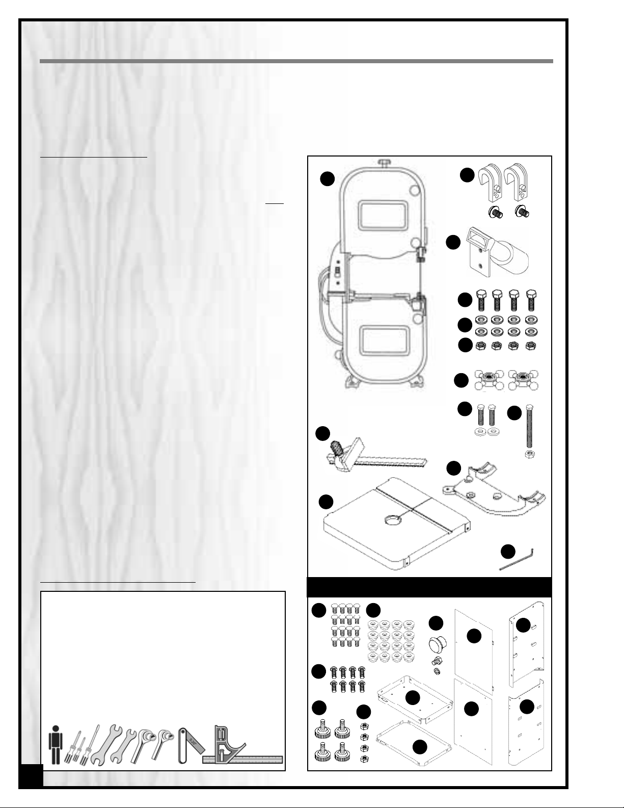
LIST OF CONTENTS
Once the parts have been removed from the packag-
ing, you should have the following items:
QTY
A- BANDSAW . . . . . . . . . . . . . . . . . . . . . . . . . . . . . . . . . . .1
B- POWER CORD HOOK W/SCREW . . . . . . . . . . . . . . . .2
C- DUST PORT . . . . . . . . . . . . . . . . . . . . . . . . . . . . . . . . . . . . .1
D- HEX HEAD BOLT . . . . . . . . . . . . . . . . . . . . . . . . . . . . . .4
E- FLAT WASHER . . . . . . . . . . . . . . . . . . . . . . . . . . . . . . . .8
F- HEX NUT . . . . . . . . . . . . . . . . . . . . . . . . . . . . . . . . . . . .4
G- LOCK KNOB . . . . . . . . . . . . . . . . . . . . . . . . . . . . . . . . .2
H- MEDIUM HEX HEAD HEAD BOLT W/FLAT WASHER . . .2
I- LONG HEX HEAD BOLT W/HEX NUT . . . . . . . . . . . . . .1
J- MITER GAUGE . . . . . . . . . . . . . . . . . . . . . . . . . . . . . . .1
K- TABLE TILT BRACKET . . . . . . . . . . . . . . . . . . . . . . . . . . .1
L- TABLE . . . . . . . . . . . . . . . . . . . . . . . . . . . . . . . . . . . . . .1
M- 3 MM ALLEN KEY . . . . . . . . . . . . . . . . . . . . . . . . . . . . .1
N- CARRIAGE BOLT . . . . . . . . . . . . . . . . . . . . . . . . . . . . .16
O- FLANGE NUT . . . . . . . . . . . . . . . . . . . . . . . . . . . . . . . .16
P- PHILLIPS HEAD SCREW . . . . . . . . . . . . . . . . . . . . . . . . .8
Q- LEVELING FOOT . . . . . . . . . . . . . . . . . . . . . . . . . . . . . .4
R- HEX NUT . . . . . . . . . . . . . . . . . . . . . . . . . . . . . . . . . . . .4
S- DOOR KNOB W/HEX BOLT AND FLAT WASHER . . . . .1
T- STAND TOP PLATE . . . . . . . . . . . . . . . . . . . . . . . . . . . . .1
U- STAND TOOL TRAY . . . . . . . . . . . . . . . . . . . . . . . . . . . .1
V- STAND DOOR . . . . . . . . . . . . . . . . . . . . . . . . . . . . . . . .1
W- STAND REAR PANEL . . . . . . . . . . . . . . . . . . . . . . . . . . .1
X- STAND LEFT SIDE PANEL . . . . . . . . . . . . . . . . . . . . . . . .1
Y- STAND RIGHT SIDE PANEL . . . . . . . . . . . . . . . . . . . . . .1
Carefully unpack and remove the unit and its components from its shipping container and check for missing or
damaged items as per the list of contents below.
NOTE: Please report any damaged or missing items to your GENERAL® INTERNATIONAL distributor immediately.
UNPACKING
ADDITIONAL REQUIREMENTS FOR SET UP
A
• Extra person for help with lifting
• Phillips screwdriver (regular and small)
• Flat head screwdriver
• 10 mm wrench and 10 mm Hex socket
• 12 mm wrench and 12 mm Hex socket
• 13mm wrench and 13 mm Hex socket
• 14 mm wrench and 14 mm Hex socket
• Feeler gauge set
• Combination square
N
T
U
V
W
X
Y
P
Q
R
B
S
G
D
E
F
H
I
O
STAND ASSEMBLY
J
K
K
M
C
8
PLACEMENT WITHIN THE SHOP / ESTABLISHING A SAFETY ZONE
THIS MODEL 90-140 M1 BANDSAW IS HEAVY (191 LBS - 87 KG). DO NOT OVER-EXERT. THE HELP OF AN ASSISTANT
WILL BE NEEDED FOR THE FOLLOWING STEP.
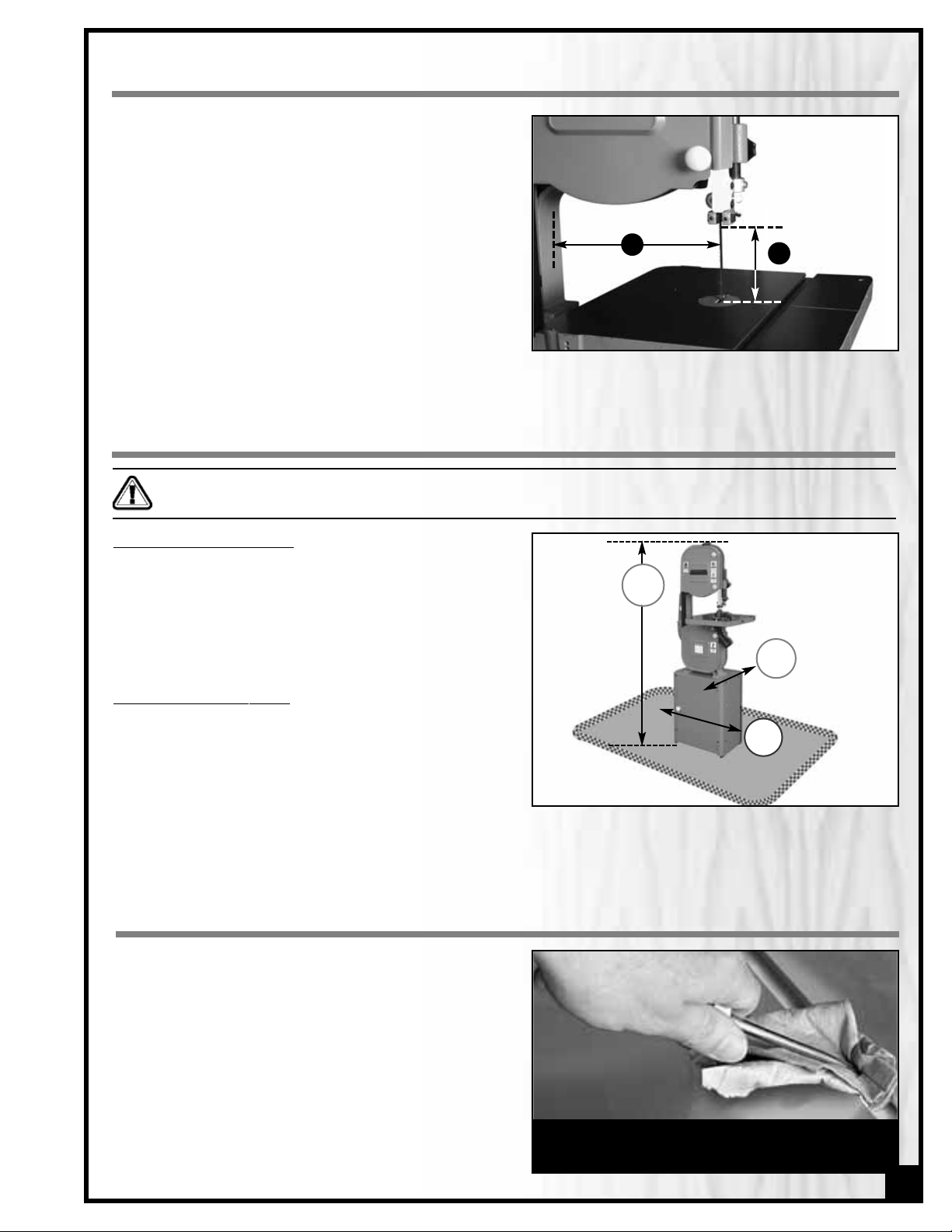
PLACEMENT WITHIN THE SHOP
This machine should be installed and operated only on a
solid, flat and stable floor that is able to support the weight
of the bandsaw 191 LBS (87 kg) and the operator.Using the
dimensions shown as a guideline,plan for placement with-
in your shop that will allow the operator to work unencum-
bered and unobstructed by foot traffic (either passing shop
visitors or other shop workers) or other tools or machinery.
BASIC FUNCTIONS OF THE UNIT
This 14" wood cutting bandsaw is supplied with a 3/8" wide
general purpose blade and is designed to accommodate
blade widths from 1/4" to 3/4".Ideal blade length f or this 90-
140 M1 model is 93 1/2" (2375 mm).
Note: Generally speaking, because the upper wheel height is
somewhat adjustable (to allow for blade tensioning), a blade
length variation of plus or minus 1/2" from the “ideal blade
length” can be accommodated.
Maximum inboard width of cut (space between the blade
and the body of the saw A) is 13 1/2".
For cutting thicker stock or for resawing, the maximum
depth of cut B (or max. workpiece height) is 6" (up to 12"
with optional “riser block kit”item #90-130A – Refer to section
“Recommended Optional Accessories for your Bandsaw”.
A
B
ESTABLISHING A SAFE
TY ZONE
For shops with frequent visitors or multiple operators, it is
advisable to establish a Safety Zone around shop machin-
ery. A clearly defined “no-go” zone on the floor around
each machine can help avoid accidents that could cause
injury to either the operator or the shop visitor.It is advisable
to take a few moments to either paint (using non-slip paint)
or using tape, define on the floor the limits or perimeter of each machines safety zone.Take steps to ensure that all
operators and shop visitors are aware that these areas are off limits whenever a machine is running for everyone
but the individual operating the unit.
The protective coating on the saw table prevents rust
from forming during shipping and storage. Remove it by
rubbing with a rag dipped in kerosene,mineral sprits or
paint thinner. (Dispose of potentially flammable solvent-
soaked rags according to manufacturer’s safety recom-
mendations.)
A putty knife, held flat to avoid scratching the surface,
may also be used to scrape off the coating followed by
clean-up with solvent. Avoid rubbing the saw’s painted
surfaces, as many solvent-based products will remove
paint.
To prevent rust, apply a light coating of paste wax or use
regular applications of any after-market surface protec-
tant or rust inhibitor.
CLEAN UP
Tip: With a screw driver, push a solvent-saturated rag into
the T-slot to remove the grease so the miter gauge will
slide freely.
9
66”
27”
16”
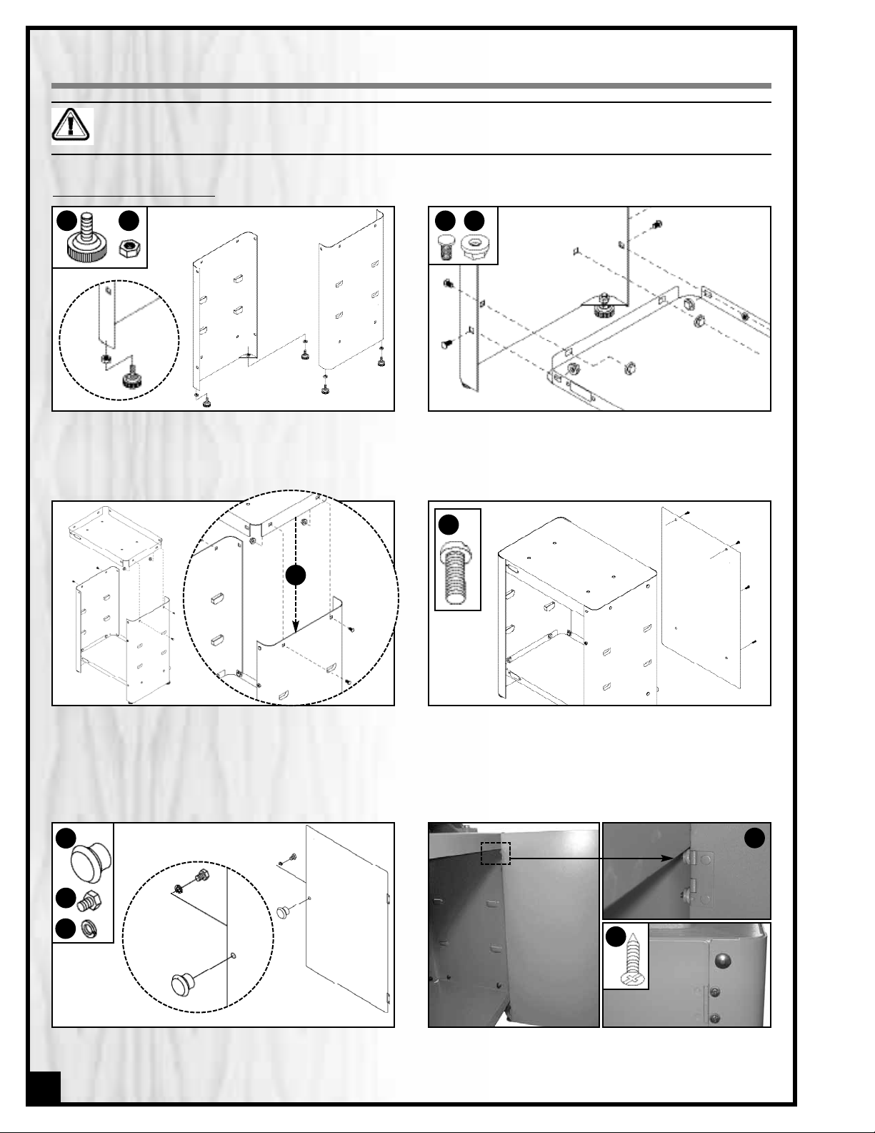
ASSEMBLY INSTRUCTIONS
SERIOUS PERSONAL INJURY COULD OCCUR IF YOU CONNECT THE MACHINE TO THE POWER SOURCE BEFORE YOU
HAVE COMPLETED THE INSTALLATION AND ASSEMBLY STEPS. DO NOT CONNECT THE MACHINE TO THE POWER
SOURCE UNTIL INSTRUCTED TO DO SO.
1. Thread a leveling foot A with a hex nut B on both
side panels as shown above.
2. Attach the left and right side panels to the tool tray
using 8 carriage bolts C and flange nuts D, then
tighten using a 12 mm open wrench.
3. Attach the top plate to the left and right side pan-
els using 4 carriage bolts C and flange nuts D as
shown above.
Note: The flanges of the top plate should fit inside the cabi-
net
E
.
4. Attach the rear panel to the top plate and tool tray
using 4 Phillips head screws F as shown above.
ASSEMBLE THE BASE CABINE
T
D
C
F
E
H
G
5. Attach the door knob G to the door using the sup-
plied hex head bolt H and lock washer I as shown
above.
I
10
A B
6. Attach the door to the hinges on the right side pa-
nel as shown using 4 Phillips head screws J.
Note: Hinges go behind side panel edge
K
.
J
K
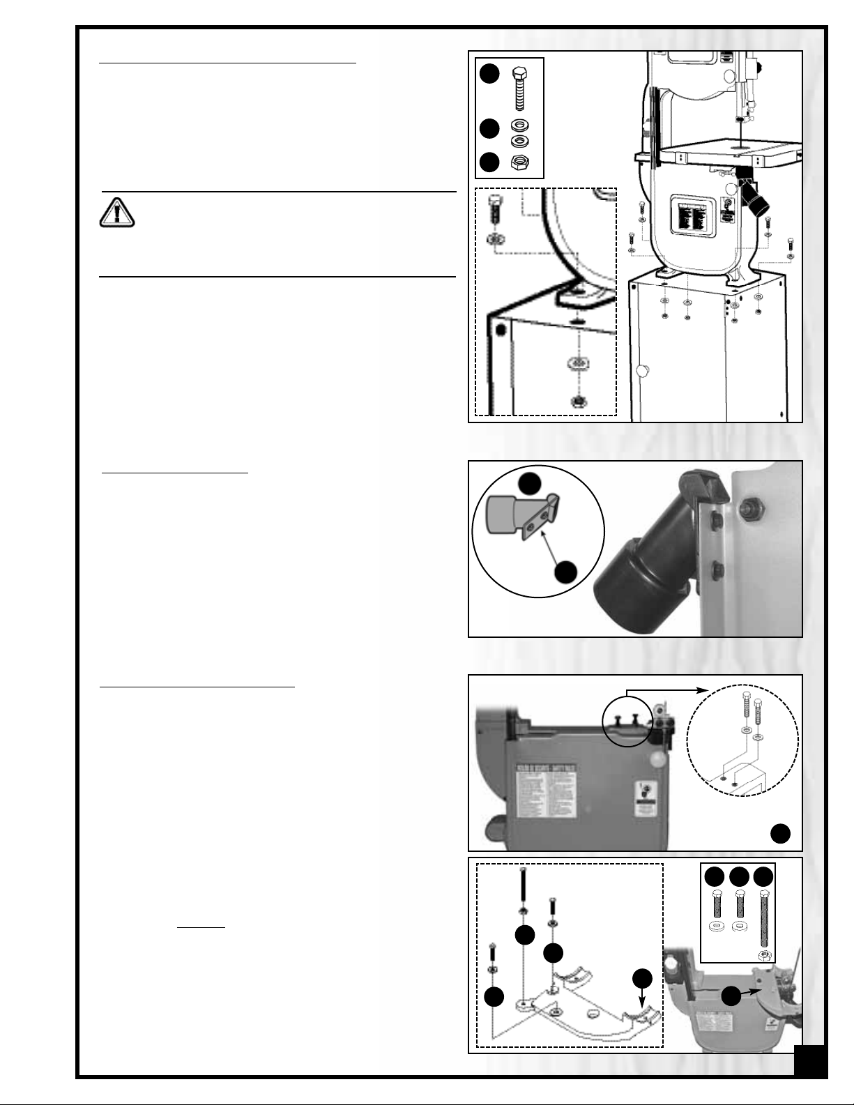
INSTALL THE BANDSAW ONTO THE BASE CABINET
The bandsaw mounts onto a base cabinet which provides
storage space for the miter gauge and replacement-
blades.
Important! Make sure all stand fasteners are firmly tightened
and that the stand cabinet is installed on a solid, flat and sta-
ble floor that is able to support the weight of the bandsaw 191
LBS (87 kg)
The bandsaw is heavy. Do not over-exert. The help of
an assistant will be needed for the following step.
Do not grip the bandsaw by the lower wheel cover
door when lifting. Keep hands away from blade at all
times.
1. Position the bandsaw over the four holes on top of the
base cabinet.
2. Using a 13 mm open end wrench and a 13 mm so-
cket wrench, secure the bandsaw to the stand as
shown using the 4 hex head bolts A, 8 flat washers B
and 4 hex nuts C.
Note: The hex nuts must be tightened from inside the cabinet.
A
B
C
The dust port A has a 2 –1/2" opening to accommodate
connection to a dust collector (not included). Install the
dust outlet on the right side of the bandsaw as follows:
1. Open the lower wheel cover door.
2. Using a 10 mm wrench, attach the dust port to the
edge of the door as shown using the hex bolts and
washers B already attached to the dust por t.
A
TTACHING THE DUST PORT
ATTACHING THE TABLE-TILT BRACKET
The work table mounts on a bracket which allows adjust-
ment from flat (0°) to any angle up to 45° to the right.
Adjustments can be made easily with the angle scale and
lock knobs.
1. Remove the two hex bolts and washers from the lower
wheel housing A.
2. Place the table-tilt bracket B on the lower wheel hous-
ing as shown in C and align holes to the threaded
holes in the lower wheel housing (hole D is not used).
3. Place washers on the two hex bolts E and F and in-
sert the bolts through the table-tilt bracket holes and
into the threaded holes in the lower wheel housing.
4. Tighten loosely
, using a 12 mm open end wrench
and 12 mm socket wrench.
5. Thread a nut onto the longer table-stop bolt D and
screw the bolt into the hole on the rear tab of the table
tilt bracket.
* Final tightening will be done after centering the table
opening with the blade.
LOWER WHEEL HOUSING
A
NOT USED
B
C
D
E
F
E
F
D
11
A
B
 Loading...