


SETUP & OPERATION MANUAL
FEATURES
Combination riving style splitter and seethrough blade guard with anti-kickback pawls, and a second European style riving knife also included.
Extra large precision ground 29” x 42” cast-iron table including two 11” full cast-iron extension wings.
Magnetic 2-step safety switch to prevent unwanted or unintentional start-up is equipped with an extra-large easy access stop panel and a lock-out key to prevent unauthorized use of the saw.
Ruggedly built saw carriage with solid cast-iron cabinet mounted trunnions.
Deluxe Excalibur sliding rip fence system with 50” rails.
Large motor cover door for full, easy access to motor and belt.
Convenient arbor lock for fast one-tool blade changes.
Powerful, totally enclosed fan cooled (T.E.F.C.) industrial motor with multi-groove V-belt drive for longer belt life and more efficient transfer of power.
Deluxe cast-iron miter gauge included.
Onboard storage mounts for fence, miter gauge and arbor wrench.
SPECIFICATIONS
•Blade/Arbor diameter
10” (25.4 mm) / 5⁄8” (16 mm)
•Arbor tilt range 0°- 45° (left)
•Maximum depth of cut at 90°/45° 3” (77 mm) / 2 1⁄8” (54 mm)
•Dado capacity 13⁄16” (21 mm)
•Dust port 4” (102 mm)
•Arbor speed 4300 rpm
•Table height 34” (863 mm)
•Table size (w/extension wings) 42” x 29” (1066 x 736 mm)
•Base dimensions (l x w) 21” x 23” (533 x 583 mm)
•Motor
M1 3 HP, 220 V, 1 ph, 11.7 A
M2 5 HP, 220 V, 3 ph, 13 A
M3 5 HP, 600 V, 3 ph, 4.7 A
•Weight
524 lbs (238 kg)
Version 2_Revision 7 - May 2015
10" TILTING CABINET SAW
- LEFT TILT
MODEL*Shown with optional table board and legs (50-270KDL)
#50-270*
© Copyright General International

GENERAL® INTERNATIONAL
8360 Champ-d’Eau, Montreal (Quebec) Canada H1P 1Y3 Telephone (514) 326-1161 • Fax (514) 326-5555 • www.general.ca
THANK YOU for choosing this General® International model 50-270 10” left tilting cabinet saw. This saw has been carefully tested and inspected before shipment and if properly used and maintained, will provide you with years of reliable service. For your safety, as well as to ensure optimum performance and trouble-free operation, and to get the most from your investment, please take the time to read this manual before assembling, installing and operating the unit.
The manual’s purpose is to familiarize you with the safe operation, basic function, and features of this saw as well as the set-up, maintenance and identification of its parts and components. This manual is not intended as a substitute for formal woodworking instruction, nor to offer the user instruction in the craft of woodworking. If you are not sure about the safety of performing a certain operation or procedure, do not proceed until you can confirm, from knowledgeable and qualified sources, that it is safe to do so.
Once you’ve read through these instructions, keep this manual handy for future reference.
Disclaimer: The information and specifications in this manual pertain to the unit as it was supplied from the factory at the time of printing. Because we are committed to making constant improvements, General® Inter-national reserves the right to make changes to components, parts or features of this unit as deemed necessary, without prior notice and without obligation to install any such changes on previously delivered units. Reasonable care is taken at the factory to ensure that the specifications and information in this manual corresponds with that of the unit with which it was
supplied. However, special orders and “after factory” modifications may render some or all information in this manual inapplicable to your machine. Further, as several generations of this model of saw and several versions of this manual may be in circulation, if you own an earlier or later version of this unit, this manual may not depict your machine exactly. If you have any doubts or questions contact your retailer or our support line with the model and serial number of your unit for clarification.

GENERAL® INTERNATIONAL WARRANTY
All component parts of General® International and Excalibur by General International® products are carefully inspected during all stages of production and each unit is thoroughly inspected upon completion of assembly.
Limited Lifetime Warranty
Because of our commitment to quality and customer satisfaction, General® International agrees to repair or replace any part or component which upon examination, proves to be defective in either workmanship or material to the original purchaser for the life of the tool. However, the Limited Lifetime Warranty does not cover any product used for professional or commercial production purposes nor for industrial or educational applications. Such cases are covered by our Standard 2-year Limited Warranty only. The Limited Lifetime Warranty is also subject to the “Conditions and Exceptions” as listed below.
Standard 2-Years Limited Warranty
All products not covered by our lifetime warranty including products used in commercial, industrial and educational applications are warranted for a period of 2 years (24 months) from the date of purchase. General® International agrees to repair or replace any part or component which upon examination, proves to be defective in either workmanship or material to the original purchaser during this 2-year warranty period, subject to the “conditions and exceptions” as listed below.
To file a Claim
To file a claim under our Standard 2-year Limited Warranty or under our Limited Lifetime Warranty, all defective parts, components or machinery must be returned freight or postage prepaid to General® International, or to a nearby distributor, repair center or other location designated by General® International. For further details call our service department at 1-888-949-1161 or your local distributor for assistance when filing your claim.
Along with the return of the product being claimed for warranty, a copy of the original proof of purchase and a “letter of claim” must be included (a warranty claim form can also be used and can be obtained, upon request, from General® International or an authorized distributor) clearly stating the model and serial number of the unit (if applicable) and including an explanation of the complaint or presumed defect in material or workmanship.
CONDITIONS AND EXCEPTIONS:
This coverage is extended to the original purchaser only. Prior warranty registration is not required but documented proof of purchase i.e. a copy of original sales invoice or receipt showing the date and location of the purchase as well as the purchase price paid, must be provided at the time of claim.
Warranty does not include failures, breakage or defects deemed after inspection by General® International to have been directly or indirectly caused by or resulting from; improper use, or lack of or improper maintenance, misuse or abuse, negligence, accidents, damage in handling or transport, or normal wear and tear of any generally considered consumable parts or components.
Repairs made without the written consent of General® International will void all warranty.

TABLE OF CONTENTS |
|
Rules for safe operation..................................................................................................... |
5 |
Electrical requirements....................................................................................................... |
6 |
Identification of main parts and components................................................................... |
7 |
Basic functions................................................................................................................... |
8 |
Installation.......................................................................................................................... |
8 |
Placement within the shop................................................................................................................................. |
8 |
Esablishing a safety zone................................................................................................................................... |
8 |
Unpacking.......................................................................................................................... |
9 |
Clean up........................................................................................................................... |
10 |
Assembly instructions.................................................................................................. |
10-12 |
Install the blade tilt adjustment handwheel.................................................................................................. |
10 |
Install miter gauge & fence storage brackets............................................................................................... |
11 |
Mount the switch................................................................................................................................................ |
11 |
Install the table extension wings...................................................................................................................... |
11 |
Install the motor cover...................................................................................................................................... |
11 |
Install the fence assembly............................................................................................... |
12 |
Front fence rail................................................................................................................................................... |
12 |
Rear fence rail.................................................................................................................................................... |
12 |
Connecting to dust collector........................................................................................... |
13 |
Install/remove a saw blade............................................................................................. |
13 |
Install and adjust riving knife........................................................................................... |
14 |
Select a riving knife........................................................................................................................................... |
14 |
Removal/Installation......................................................................................................................................... |
15 |
Blade cover and riving knife assembly.......................................................................................................... |
15 |
Adjustment/alignment...................................................................................................................................... |
16 |
Setting the splitter/knife 90° to the table......................................................................................................... |
16 |
Setting the splitter/knife parallel and centered on the blade..................................................................... |
16 |
Level the table insert......................................................................................................................................... |
17 |
Basic adjustments and controls....................................................................................... |
17 |
Connecting to a power source....................................................................................................................... |
17 |
ON/OFF magnetic power switch..................................................................................................................... |
17 |
Overload protection......................................................................................................................................... |
17 |
Blade height adjustment.................................................................................................................................. |
18 |
Blade tilt(bevel) adjustment............................................................................................................................. |
18 |
Operating instructions...................................................................................................... |
18 |
Types of cuts................................................................................................................ |
19-20 |
Adjusting and using the miter gauge.............................................................................. |
20 |
Using a dado blade.......................................................................................................... |
22 |
Maintenance and adjustments........................................................................................ |
22 |
Recommended optional accessories.............................................................................. |
24 |
Parts list & diagrams................................................................................................... |
25-33 |
Contact information......................................................................................................... |
34 |

RULES FOR SAFE OPERATION
To help ensure safe operation, please take a moment to learn the machine’s applications and limitations, as well as potential hazards. General® International disclaims any real or implied warranty and holds itself harmless for any injury that may result from the improper use of it’s equipment.
1.Do not operate the saw when tired, distracted, or 15. Use suitable support when cutting stock that does
under the effects of drugs, alcohol or any medication that impairs reflexes or alertness.
2.The work area should be well lit, clean and free of debris.
3.Keep children and visitors at a safe distance when the saw is in operation; do not permit them to operate the saw.
4.Childproof and tamper proof your shop and all machinery with locks, master electrical switches and switch keys, to prevent unauthorized or unsupervised use.
5.Stay alert! Give your work your undivided attention. Even a momentary distraction can lead to serious injury.
6.Fine particulate dust is a carcinogen that can be hazardous to health. Work in a well-ventilated area and whenever possible use a dust collector and wear eye, ear and respiratory protection devices.
7.Do not wear loose clothing, gloves, bracelets, necklaces or other jewelry while the saw is in operation. Wear protective hair covering to contain long hair and wear non-slip footwear.
8.Be sure that adjusting wrenches, tools, drinks and other clutter are removed from the machine and/ or the feed table surface before operating.
9.Keep hands well away from the blade and all moving parts. Use a brush, not hands, to clear away chips and dust.
10.Be sure that the blade is securely installed and in proper cutting direction before operation.
11.Be sure the blade has gained full operating speed before beginning to cut.
12.Always use a clean, properly sharpened blade. Dirty or dull blades are unsafe and can lead to accidents.
13.If using a power feeder, stop the feeder before stopping the table saw.
14.Do not push or force stock into the blade. The saw will perform better and more safely when working at the rate for which it was designed.
not have a flat surface. Always hold stock firmly against the fence when ripping, or against the miter gauge when cross cutting.
16.To minimize risk of injury in the event of workpiece kickback, never stand directly in-line with the blade or in the potential kickback path of the workpiece.
17.Avoid working from awkward or off balance positions. Do not overreach while cutting; keep both feet on floor. Never lean over or reach over the blade and never pull the workpiece over the blade from behind. Use out feed support or have an assistant help when ripping long material.
18.Keep blade guards in place and in working order. If a guard must be removed for maintenance or cleaning, be sure it is properly re-attached before using the tool again.
19.Never leave the machine unattended while it is running or with the power on.
20.Use of parts and accessories NOT recommended by GENERAL® INTERNATIONAL may result in equipment malfunction or risk of injury.
21.Never stand on machinery. Serious injury could result if the tool is tipped over or if the blade is unintentionally contacted.
22.Always disconnect tool from power before servicing or changing accessories such as blades, or before performing any maintenance, cleaning or adjustments, or if the machine will be left unattended.
23.Make sure that switch is in “OFF” position before plugging in the power cord.
24.Make sure the tool is properly grounded.If equipped with a 3-prong plug it should be used with a threepole receptacle. Never remove the third prong.
25.Do not use this saw for any purpose other than its intended use. If used for other purposes, GENERAL® INTERNATIONAL disclaims any real implied warranty and holds itself harmless for any injury, which may result from that use.
5

ELECTRICAL REQUIREMENTS
BEFORE CONNECTING THE MACHINE TO THE POWER SOURCE, VERIFY THAT THE VOLTAGE OF YOUR POWER SUPPLY CORRESPONDS WITH THE VOLTAGE SPECIFIED ON THE MOTOR I.D. NAMEPLATE. A POWER SOURCE WITH GREATER VOLTAGE THAN NEEDED CAN RESULT IN SERIOUS INJURY TO THE USER AS WELL AS DAMAGE TO THE MACHINE. IF IN DOUBT, CONTACT A QUALIFIED ELECTRICIAN BEFORE CONNECTING TO THE POWER SOURCE.
THIS TOOL IS FOR INDOOR USE ONLY. DO NOT EXPOSE TO RAIN OR USE IN WET OR DAMP LOCATIONS.
Note: voltage requirements and amperage draw for M2 & M3 3-phase motors may not be fully described in this manual. For complete electrical requirements refer to the motor I.D. name plate on the machine. If in doubt consult a licensed qualified electrician before proceeding.
CIRCUIT CAPACITY
Make sure that the wires in your circuit are capable of handling the amperage draw from your machine, as well as any other machines that could be operating on the same circuit. If you are unsure, consult a qualified electrician. If the circuit breaker trips or the fuse blows regularly, your machine may be operating on a circuit that is close to its amperage draw capacity. However, if an unusual amperage draw does not exist and a power failure still occurs, contact a qualified technician or our service department.
|
|
EXTENSION CORDS |
|
|
|
|
|
||||
|
|
|
|
|
|
|
|||||
ELECTRICAL CONNECTIONS |
The use of an extension cord is not generally recom- |
||||||||||
mended for 220 V equipment. If you find it necessary, |
|||||||||||
Both a manual circuit breaker (or similar device) as well |
use only 3-wire extension cords that have 3-prong |
||||||||||
as an electrical plug are recommended and should |
grounding plug and a matching 3-pole receptacle that |
||||||||||
be installed by a qualified electrician. Use locally ap- |
accepts the tool’s plug. Repair or replace a damaged |
||||||||||
proved wire that includes a separate grounding wire |
extension cord or plug immediately. |
|
|
||||||||
and a 3-prong grounding type plug A with a matching |
Make sure the cord rating is suitable for the amper- |
||||||||||
receptacle B . |
age listed on the motor I.D. plate. An undersized |
||||||||||
|
|
cord will cause a drop in line voltage resulting in |
|||||||||
GROUNDING INSTRUCTIONS |
loss of power and |
overheating. The accompany- |
|||||||||
ing chart shows the correct size extension cord to be |
|||||||||||
In the event of an electrical malfunction or short circuit, |
|||||||||||
used based on cord length and motor I.D. plate amp |
|||||||||||
grounding reduces the risk of electric shock to the op- |
rating. If |
in |
doubt, |
use the |
next |
heavier |
gauge. |
||||
erator. The motor of the “M1” model of this machine is |
The smaller |
the number, |
the |
heavier the |
gauge. |
||||||
wired for 220 V single phase operation. |
|
|
|
|
|
|
|
|
|
||
As with many stationary industrial type machines, be- |
|
|
|
|
|
|
|
|
|
||
cause each installation situation is unique, this machine |
|
|
|
|
|
|
|
|
|
||
is supplied without a power cord or plug. |
|
|
|
|
|
|
|
|
|
||
The installation of an appropriate power cord and plug |
TABLE - MINIMUM GAUGE FOR CORD |
|
|||||||||
must be performed by a qualified electrician. The ma- |
AMPERE |
|
|
|
TOTAL LENGTH OF CORD IN FEET |
|
|||||
chine must be connected to an electrical source using |
220 VOLTS |
|
50 FEET |
100 FEET |
200 FEET |
300 FEET |
|||||
RATING |
|
||||||||||
a power cord that has a grounding wire, which must |
|
|
|
|
AWG |
|
|
||||
|
|
|
|
|
|
|
|||||
also be properly connected to the grounding prong |
< 5 |
-------> |
|
18 |
|
16 |
16 |
14 |
|||
on the plug. The outlet must be properly installed and |
|
|
|||||||||
6 TO 10 |
-------> |
|
18 |
|
16 |
14 |
12 |
||||
grounded and all electrical connections must be made |
|
|
|||||||||
10 TO 12 |
-------> |
|
16 |
|
16 |
14 |
12 |
||||
in accordance with all local codes and regulations. |
|
|
|||||||||
12 TO 16 |
-------> |
|
14 |
|
12 |
* NR |
* NR |
||||
|
|
|
|
||||||||
|
|
* NR = Not Recommended |
|
|
|
|
|||||
6
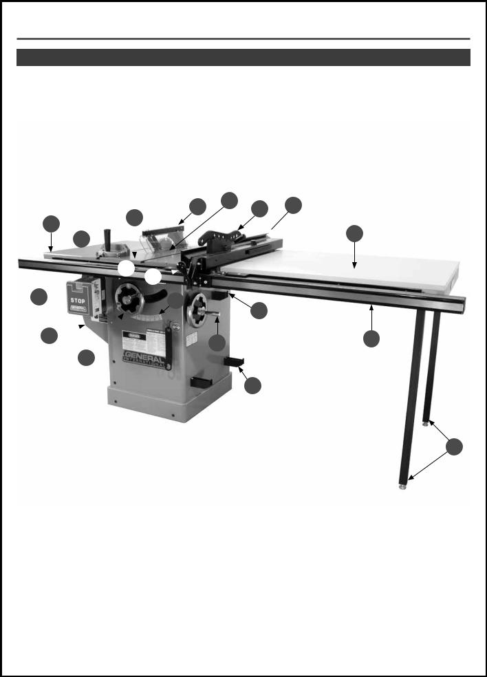
IDENTIFICATION OF MAIN PARTS AND COMPONENTS
FRONT VIEW
D E F G
A C
B

 J
J
H 
I 
S  P
P
O
R 
 N L
N L
Q
 M
M
K
A. |
LEFT TABLE EXTENSION WING |
K. |
SUPPORT LEGS (OPTIONAL) |
B. |
MITER GAUGE |
L. |
FRONT FENCE RAIL |
C. |
MAIN TABLE |
M. |
T-FENCE STORAGE BRACKETS |
D. |
SPLITTER/BLADE COVER |
N. |
BLADE TILT ADJUSTMENT HANDWHEEL |
E. |
TABLE INSERT |
O. |
MITER GAUGE STORAGE BRACKET |
F. |
PUSH STICK |
P. |
BEVEL ANGLE SCALE |
G. |
RIP FENCE |
Q. |
BLADE HEIGHT ADJUSTMENT HANDWHEEL |
H. |
RIGHT TABLE EXTENSION WING |
R. |
MOTOR COVER |
I. |
FENCE LOCKING LEVER |
S. |
MAGNETIC SAFETY SWITCH |
J. |
EXTENSION TABLE (OPTIONAL) |
|
|
7
BASIC FUNCTIONS
The General International model 50-270 cabinet saw is available with various motor size and electrical voltage requirement options (see manual coverpage for complete list).
This cabinet saw has been designed for cutting solid wood as well as manufactured wood materials such as plywood, wood paneling, particleboard, mdf and other wood based by-products.
This saw is not designed for cutting metals nor for cutting any materials other than wood or wood based stock. This saw is designed for use with maximum 10” (254 mm) diameter blades having a center hole diameter of 5/8”.
The blade can be raised to cut a maximum stock thickness of 3” with the blade set 90° to the table. The blade can be tilted up to 45° to the left for bevel cuts to a maximum stock thickness of 2 1/8”. Using any standard after market 8”diameter stacked dado blade set (not included), the maximum dado cutting capacity of this saw is 13/16”. Note: for safer dado cutting, an optional dado table insert (#50-302) can be purchased through your General International distributor.
To encourage safety through the proper use of either the supplied riving style splitter/blade guard assembly or the European style riving knife the 50-270 is designed with a quick install/quick release feature allowing the user to install or remove either of these safety components in seconds.
INSTALLATION
THIS MODEL 50-270 10” CABINET SAW IS HEAVY. DO NOT OVER-EXERT. A HOIST OR FORKLIFT WITH STRAPS SHOULD BE USED TO LIFT THIS MACHINE. TO LIMIT THE RISK OF SERIOUS INJURY OR DAMAGE TO THE MACHINE, ANY EQUIPMENT USED TO LIFT THIS MACHINE SHOULD HAVE A RATED CAPACITY IN EXCESS OF 524 LBS (238 KG).
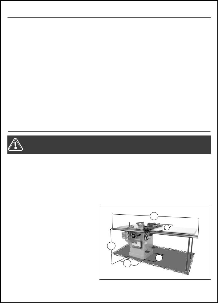
PLACEMENT WITHIN THE SHOP
This machine should be installed and operated only on a solid, flat and stable floor that is able to support the weight of the sander (524 lbs - 238 kg) and the operator.
Using the dimensions shown as a guideline, plan for placement within your shop that will allow the operator to work unencumbered and unobstructed by foot traffic (either passing shop visitors or other shop workers) or other tools or machinery.
ESTABLISHING A SAFETY ZONE
For shops with frequent visitors or multiple operators, it is advisable to establish a safety zone around shop machinery. A clearly defined “nogo” zone on the floor around each machine can help avoid accidents that could cause injury to either the operator or the shop visitor.
It is advisable to take a few moments to either paint (using non-slip paint) or using tape, define on the floor the limits or perimeter of each machines safety zone.
Take steps to ensure that all operators and shop visitors are aware that these areas are off limits whenever a machine is running for everyone but the individual operating the unit.
85" |
44" |
34" |
23" |
21" |
*Model 50-270KDL shown |
8
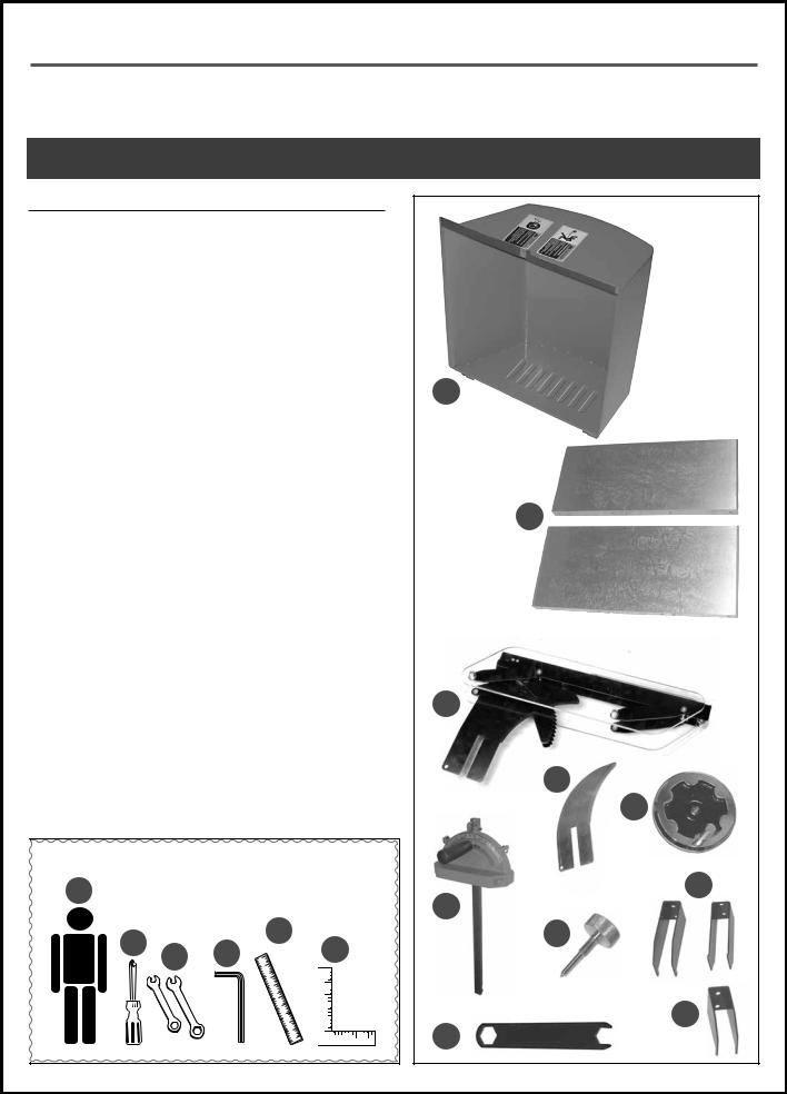
UNPACKING
Carefully unpack and remove the saw and its components from the shipping crate and check for damaged or missing items as per the list of contents below.
NOTE: PLEASE REPORT ANY DAMAGED OR MISSING ITEMS TO YOUR GENERAL® INTERNATIONAL DISTRIBUTOR IMMEDIATELY.
LIST OF CONTENTS |
QTY |
|
A. |
SAW (NOT SHOWN)................................................................. |
1 |
B. |
MOTOR COVER........................................................................ |
1 |
C. |
TABLE EXTENSION .................................................................... |
2 |
D. |
BLADE COVER/SPLITTER........................................................... |
1 |
E. |
RIVING KNIFE........................................................................... |
1 |
F. |
BLADE TILT ADJUSTMENT HANDWHEEL.................................... |
1 |
G. |
MITER GAUGE........................................................................... |
1 |
H. |
BLADE TILT HANDWHEEL LOCK KNOB..................................... |
1 |
I. |
FENCE STORAGE BRACKET...................................................... |
2 |
J. |
MITER GAUGE STORAGE BRACKET.......................................... |
1 |
K. |
ARBOR WRENCH...................................................................... |
1 |
Note: The Excalibur SLF35T52 rip fence and rails are packaged separately.
ADDITIONAL REQUIREMENTS FOR SET UP
A.EXTRA PERSON FOR HELP WITH LIFTING
B.PHILLIPS SCREWDRIVER
C.COMBINATION WRENCHES 10 MM AND 7/16”
D.3 MM AND 4 MM ALLEN KEYS
E.STRAIGHTEDGE
F.MACHINIST SQUARE OR TRIANGLE SQUARE
A
E
B C D G
B
C
D
E
F
I
G
H
J
K
9

CLEAN UP
The protective coating on the saw table prevents rust from forming during shipping and storage. Remove it by rubbing with a rag dipped in kerosene, mineral spirits or paint thinner. (Dispose of potentially flammable solvent-soaked rags according to manufacturer’s safety recommendations).
A putty knife, held flat to avoid scratching the surface, may also be used to scrape off the coating followed by clean-up with solvent. Avoid rubbing the saw’s painted surfaces, as many solvent-based products will remove paint.
To prevent rust, apply a light coating of paste wax or use regular applications of any after-market surface protectant or rust inhibitor.
TIP: WITH A SCREWDRIVER, PUSH A SOLVENT-SATURATED RAG INTO THE T-SLOTS TO REMOVE THE GREASE.
ASSEMBLY INSTRUCTIONS
BEFORE STARTING THE ASSEMBLY, MAKE SURE THAT THE SWITCH IS IN THE “OFF” POSITION AND THAT THE POWER CORD IS UNPLUGGED. DO NOT PLUG IN OR TURN ON THE SAW UNTIL YOU HAVE COMPLETED THE ASSEMBLY AND INSTALLATION STEPS DESCRIBED IN THIS SECTION OF THE MANUAL.
INSTALL THE BLADE TILT ADJUSTMENT HANDWHEEL
|
RIGHT SIDE VIEW |
|
|
|
F |
|
B |
|
|
C |
D |
|
|
|
A |
|
E |
|
|
1. Install the blade tilt adjustment handwheel A |
2. Tighten the screw D to secure the handwheel on |
|
ontthe shaft B on the right side of the saw. |
the shaft using a 4 mm Allen key, then thread the |
|
Note: First remove the adhesive tape C that holds the |
lock knob E into the handwheel shaft F to secure |
|
the handwheel in place. |
||
key in the shaft. |
||
Note: To limit the potential for damage in transport, this |
|
|
|
||
table saw is shipped from the factory with the motor sit- |
|
|
ting on a styrofoam block G for support. |
|
|
Turn the handwheel H, located on the right side of the |
|
|
saw, counter-clockwise to raise the motor enough to re- |
|
|
move the styrofoam block |
|
H
G 
10

INSTALL MITER GAUGE & FENCE STORAGE BRACKETS
Install the miter gauge storage bracket J (the smaller one) and the fence storage brackets K on the right side of the saw as shown in L, using the screws M already mounted on the right side of the cabinet.
MOUNT THE SWITCH
N
O
J |
M |
K |
L |
P
Q
1.Loosen the two bolts on front of the saw N and re- 2. Slide the switch mounting bracket onto the front
move the two bolts on the left side of the saw O.
bolts P and tighten from inside the cabinet with a 10 mm socket wrench, then re-install and tighten the side bolts Q.
INSTALL THE TABLE EXTENSION WINGS
R |
Level here |
|
S
T
Flush here
Attach the table extension wings to the main table using the 7/16” mm hex head bolts (3 per wing) already mounted on both sides of the main table R. Align the table extensions with the table and loosely attach the bolts. Place a straightedge on the table and extension as shown S to align the extension table and then tighten down the bolts.
Note: Be sure that the table extension wings are flush with front edge of table T.
INSTALL THE MOTOR COVER
V 
W
Install the motor cover door on the left side of the saw by inserting the pins V into the hinge sockets W.
11
 Loading...