


SETUP & OPERATION MANUAL
FEATURES
 Optimum sanding results without the need for special operator skills.
 High quality conveyor belt for long service life.
 Variable feed rate from 3-20 FPM.
 Conveyor motor equipped with independant safety switch with removable key.
 Magnetic safety switch on main motor.
 Side and rear extension tables for easier stock handling.
 Reinforced pressure roller brackets.
 Large metal hand wheel controls sanding head height for thickness adjustment.
Internal dust shroud for efficient dust control.
Totally enclosed stand with storage compartment.
 Ability to sand up to 30”material in two passes. (Finish sanding may be required)
SPECIFICATIONS
MAXIMUM SANDING WIDTH
15” (380 MM) / *30” (*IN 2 PASSES)
MIN / MAX SANDING THICKNESS 1/4” (6 MM) / 4” (102 MM)
MINIMUM SANDING LENGTH 5” (127 MM)
FEED RATE
3 TO 20 FPM - VARIABLE
SANDING BELT SIZE
15” X 39 1⁄2” (381 X 1003 MM)
CONTACT ROLLER DIAMETER 2 1⁄2” (82 MM)
OVERALL DIMENSIONS (L X W X H) WITH TABLES FULLY EXTENDED
39” X 52” X 64 1⁄2”
(991 X 1321 X 1638 MM)
CONVEYOR MOTOR 1⁄6 HP
MAIN MOTOR
3 HP, 220 V, 1 PH, 1720 RPM
WEIGHT
400 LBS / 182 KG
15” OPEN TYPE WIDE BELT SANDER
MODEL
#15-030 M1
REVISION 1 - September 25/08
© Copyright General® International 09/2008

GENERAL® INTERNATIONAL
8360 Champ-d’Eau, Montreal (Quebec) Canada H1P 1Y3 Telephone (514) 326-1161 • Fax (514) 326-5555 • www.general.ca
THANK YOU for choosing this General® International model 15-030 15” Open Type Wide Belt Sander. This sander has been carefully tested and inspected before shipment and if properly used and maintained, will provide you with years of reliable service. To ensure optimum performance and trouble-free operation, and to get the most from your investment, please take the time to read this manual before assembling, installing and operating the unit.
The manual’s purpose is to familiarize you with the safe operation, basic function, and features of this sander as well as the set-up, maintenance and identification of its parts and components. This manual is not intended as a substitute for formal woodworking instruction, nor to offer the user instruction in the craft of woodworking. If you are not sure about the safety of performing a certain operation or procedure, do not proceed until you can confirm, from knowledgeable and qualified sources, that it is safe to do so.
Once you’ve read through these instructions, keep this manual handy for future reference.
Disclaimer: The information and specifications in this manual pertain to the unit as it was supplied from the factory at the time of printing. Because we are committed to making constant improvements, General® International reserves the right to make changes to components, parts or features of this unit as deemed necessary, without prior notice and without obligation to install any such changes on previously delivered units. Reasonable care is taken at the factory to ensure that the specifications and information in this manual corres-
ponds with that of the unit with which it was supplied. However, special orders and “after factory” modifications may render some or all information in this manual inapplicable to your machine. Further, as several generations of this model of sander and several versions of this manual may be in circulation, if you own an earlier or later version of this unit, this manual may not depict your machine exactly. If you have any doubts or questions contact your retailer or our support line with the model and serial number of your unit for clarification.

GENERAL® & GENERAL® INTERNATIONAL WARRANTY
All component parts of General®, General® International and Excalibur by General International ® products are carefully inspected during all stages of production and each unit is thoroughly inspected upon completion of assembly.
Limited Lifetime Warranty
Because of our commitment to quality and customer satisfaction, General® and General® International agree to repair or replace any part or component which upon examination, proves to be defective in either workmanship or material to the original purchaser for the life of the tool. However, the Limited Lifetime Warranty does not cover any product used for professionnal or commercial production purposes nor for industrial or educational applications. Such cases are covered by our Standard 2-year Limited Warranty only. The Limited Lifetime Warranty is also subject to the “Conditions and Exceptions” as listed below.
Standard 2-Year Limited Warranty
All products not covered by our lifetime warranty including products used in commercial, industrial and educational applications are warranted for a period of 2 years (24 months) from the date of purchase. General® and General® International agree to repair or replace any part or component which upon examination, proves to be defective in either workmanship or material to the original purchaser during this 2-year warranty period, subject to the “conditions and exceptions” as listed below.
To file a Claim
To file a claim under our Standard 2-year Limited Warranty or under our Limited Lifetime Warranty, all defective parts, components or machinery must be returned freight or postage prepaid to General® International, or to a nearby distributor, repair center or other location designated by General® International. For further details call our service department at 1-888- 949-1161 or your local distributor for assistance when filing your claim.
Along with the return of the product being claimed for warranty, a copy of the original proof of purchase and a “letter of claim” must be included (a warranty claim form can also be used and can be obtained, upon request, from General® International or an authorized distributor) clearly stating the model and serial number of the unit (if applicable) and including an explanation of the complaint or presumed defect in material or workmanship.
CONDITIONS AND EXCEPTIONS:
This coverage is extended to the original purchaser only. Prior warranty registration is not required but documented proof of purchase i.e. a copy of original sales invoice or receipt showing the date and location of the purchase as well as the purchase price paid, must be provided at the time of claim.
Warranty does not include failures, breakage or defects deemed after inspection by General® or General® International to have been directly or indirectly caused by or resulting from: improper use, or lack of or improper maintenance, misuse or abuse, negligence, accidents, damage in handling or transport, or normal wear and tear of any generally considered consumable parts or components.
Repairs made without the written consent of General® Internationallwill void all warranty.

TABLE OF CONTENTS
SAFETY RULES . . . . . . . . . . . . . . . . . . . . . . .5
ELECTRICAL REQUIREMENTS . . . . . . . . . . . . . .6
Grounding instructions . . . . . . . . . . . . . . . . . . . . . . .6 Circuit capacity . . . . . . . . . . . . . . . . . . . . . . . . . . . . .6 Extension cords . . . . . . . . . . . . . . . . . . . . . . . . . . . . .6
IDENTIFICATION OF MAIN PARTS AND COMPONENTS . . . . . . . . . . . . . . . . . . . . . . . . . . . .7
BASIC FUNCTIONS . . . . . . . . . . . . . . . . . . . .8
UNPACKING . . . . . . . . . . . . . . . . . . . . . . . .8
List of contents . . . . . . . . . . . . . . . . . . . . . . . . . . . . . .8 Additional requirements for set up . . . . . . . . . . . . .8
PLACEMENT WITHIN THE SHOP / ESTABLISHING A SAFETY ZONE . . . . . . . . . . . . . . . . . . . . . . .9
LIFTING AND HANDLING THE MACHINE . . . . . . |
.9 |
ASSEMBLY INSTRUCTIONS . . . . . . . . . . . . . . |
10 |
Install the side and rear extension tables . . . . . . .10 Install the sanding belt . . . . . . . . . . . . . . . . . . . . . .10
CONNECTING TO A DUST COLLECTOR . . . . . . .12
BASIC ADJUSTMENTS & CONTROLS . . . . . . . .12
Connecting to a power source . . . . . . . . . . . . . . .12 Drum motor magnetic safety switch . . . . . . . . . .12 Conveyor motor switch with safety key . . . . . . . .13 Overload protection . . . . . . . . . . . . . . . . . . . . . . . .13 Sanding belt tension adjustment . . . . . . . . . . . . .14 Sanding belt tracking adjustment . . . . . . . . . . . . .14 Adjusting the sanding head height . . . . . . . . . . .15 Changing feed speed . . . . . . . . . . . . . . . . . . . . . .16
RECOMMENDED ADJUSTMENTS . . . . . . . . . . .16
Adjusting the pressure roller height . . . . . . . . . . . .16
OPERATING INSTRUCTIONS . . . . . . . . . . . . .18
Basic principles of sanding . . . . . . . . . . . . . . . . . .18 Operations step-by-step . . . . . . . . . . . . . . . . . . . . .18 To stop the machine . . . . . . . . . . . . . . . . . . . . . . . .18
MAINTENANCE . . . . . . . . . . . . . . . . . . . . . .19
Periodic maintenance . . . . . . . . . . . . . . . . . . . . . .19 Replacement of the sanding belt . . . . . . . . . . . . .19 Lubrication . . . . . . . . . . . . . . . . . . . . . . . . . . . . . . . .19
RECOMMENDED OPTIONAL ACCESSORIES . . . .20
PARTS LIST AND DIAGRAMS . . . . . . . . . . . . .21
CONTACT INFORMATION . . . . . . . . . . . . . . . .30

RULES FOR SAFE OPERATION
To help ensure safe operation, please take a moment to learn the machine’s applications and limitations, as well as potential hazards. General® International disclaims any real or implied warranty and holds itself harmless for any injury that may result from improper use of its equipment.
1.Do not operate the sander when tired, distracted, or under the effects of drugs, alcohol or any medication that impairs reflexes or alertness.
2.The working area should be well lit, clean and free of debris.
3.Keep children and visitors at a safe distance when the sander is in operation; do not permit them to operate the sander.
4.Childproof and tamper proof your shop and all machinery with locks, master electrical switches and switch keys, to prevent unauthorized or unsupervised use.
5.Stay alert! Give your work your undivided attention. Even a momentary distraction can lead to serious injury.
6.Fine particulate dust is a carcinogen that can be hazardous to health. Work in a well-ventilated area and wear eye, ear and respiratory protection devices.
7.Do not operate this sander without an adequate dust collection system properly installed and running. Operating this sander without adequate dust collection can lead to equipment malfunction or dangerous situations for the operator or other individuals in the workshop.
8.Do not wear loose clothing, gloves, bracelets, necklaces or other jewelry while the sander is in operation. Wear protective hair covering to contain long hair and wear non-slip footwear.
9.Be sure that adjusting wrenches, tools, drinks and other clutter are removed from the machine and/or the feed table surface before operating.
10.Keep hands well away from the sanding belts and all moving parts. Use a brush, not hands, to clear away sanding dust.
11.Be sure sanding belts are securely installed on the sanding drums.
12.Do not operate the sander if the sanding belts are damaged or badly worn.
13.Do not push or force the workpiece into the sander. The machine will perform better and more safely when working at the feed rate for which it was designed.
14.Avoid working from awkward or off balance positions. Do not overreach and keep both feet on floor.
15.To minimize risk of injury in the event of workpiece kickback, never stand directly in-line with the sanding belt or in the potential kickback path of the work piece.
16.Keep guards in place and in working order. If a guard must be removed for maintenance or cleaning, be sure it is properly re-attached before using the tool again.
17.Never leave the machine unattended while it is running or with the power on.
18.Use of parts and accessories NOT recommended by GENERAL→ INTERNATIONAL may result in equipment malfunction or risk of injury.
19.Never stand on the machine. Serious injury could occur if the sander is tipped over or if the sanding belt is unintentionally contacted.
20.Always disconnect the tool from the power source before servicing, changing accessories or sanding belts, or before performing any maintenance or cleaning, or if the machine will be left unattended.
21.Make sure that switch is in “OFF” position before plugging in the power cord.
22.Make sure the tool is properly grounded. If equipped with a 3-prong plug it should be used with a three-pole receptacle. Never remove the third prong.
23.Do not use the sander for other than its intended use. If used for other purposes, GENERAL→ INTER NATIONAL disclaims any real implied warranty and holds itself harmless for any injury, which may result from that use.
5
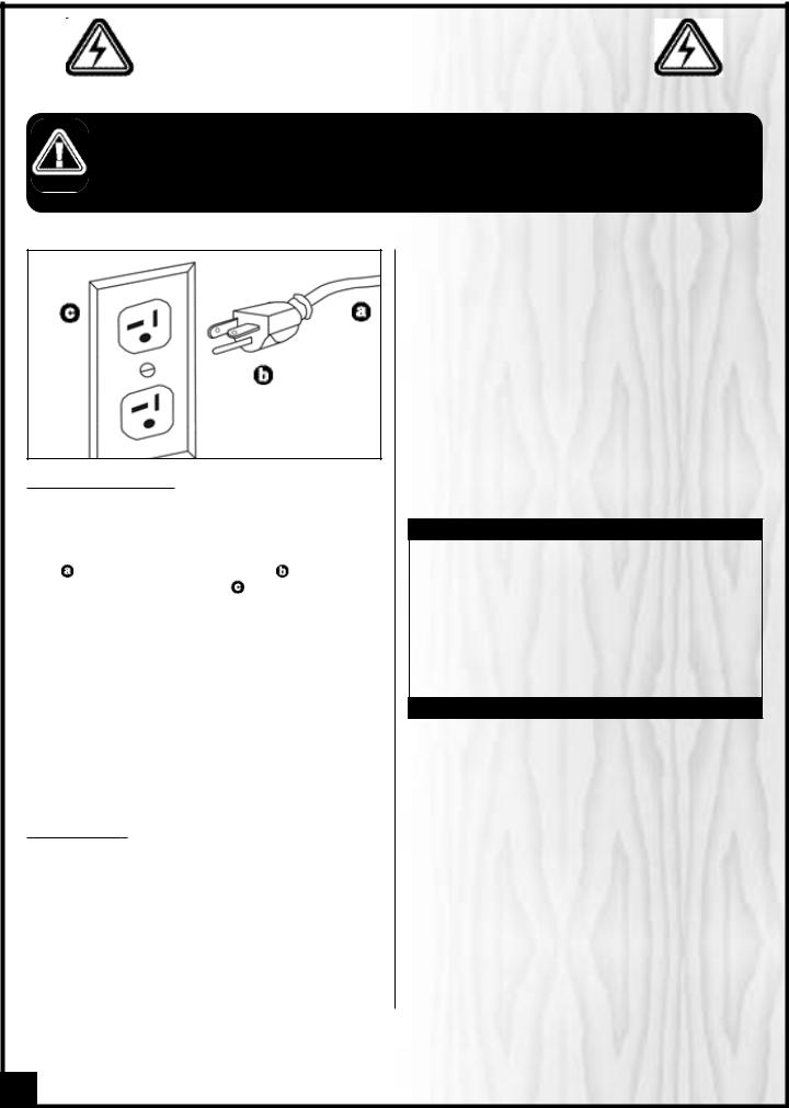
ELECTRICAL REQUIREMENTS
BEFORE CONNECTING THE MACHINE TO THE POWER SOURCE, VERIFY THAT THE VOLTAGE OF YOUR POWER SUPPLY CORRESPONDS WITH THE VOLTAGE SPECIFIED ON THE MOTOR I.D. NAMEPLATE. A POWER SOURCE WITH GREATER VOLTAGE THAN NEEDED CAN RESULT IN SERIOUS INJURY TO THE USER AS WELL AS DAMAGE TO THE MACHINE. IF IN DOUBT, CONTACT A QUALIFIED ELECTRICIAN BEFORE CONNECTING TO THE POWER SOURCE.
THIS TOOL IS FOR INDOOR USE ONLY. DO NOT EXPOSE TO RAIN OR USE IN WET OR DAMP LOCATIONS.
EXTENSION CORDS
The use of an extension cord is not generally recommended for 220V equipment. If you find it necessary, use only 3-wire extension cords that have 3-prong grounding plug and a matching 3-pole receptacle that accepts the tool’s plug. Repair or replace a damaged extension cord or plug immediately.
If you find it necessary to use an extension cord with your machine make sure the cord rating is suitable for the amperage listed on the motor I.D. plate. An undersized cord will cause a drop in line voltage resulting in loss of power and overheating. The accompanying chart shows the correct size extension cord to be used based on cord length and motor I.D. plate amp rating. If in doubt, use the next heavier gauge. The smaller the number, the heavier the gauge.
TABLE - MINIMUM GAUGE FOR CORD
|
|
TOTAL LENGTH OF CORD IN FEET |
|
||
AMPERE |
110 VOLTS |
25 FEET |
50 FEET |
100 FEET |
150 FEET |
RATING |
220 VOLTS |
50 FEET |
100 FEET |
200 FEET |
300 FEET |
|
|
|
AWG |
|
|
< 5 |
-------> |
18 |
16 |
16 |
14 |
6 TO 10 |
-------> |
18 |
16 |
14 |
12 |
10 TO 12 |
-------> |
16 |
16 |
14 |
12 |
12 TO 16 |
-------> |
14 |
12 |
* NR |
* NR |
* NR = Not Recommended
6

15” OPEN TYPE WIDE BELT SANDER |
15-030 M1 |
IDENTIFICATION OF MAIN PARTS AND COMPONENTS |
RIGHT SIDE VIEW |
DUST OUTLET |
TOP COVER DOOR |
CONVEYOR |
SIDE / REAR EXTENSION TABLES |
STAND WITH STORAGE CABINET |
FRONT WINDOW |
MAIN MOTOR MAGNETIC SAFETY SWITCH |
LEFT SIDE VIEW |
INSIDE VIEW |
HAND WHEEL SANDING HEAD HEIGHT |
ADJUSTMENT HAND WHEEL |
SANDING HEAD HEIGHT LOCKING HANDLE |
MAIN MOTOR |
CONVEYOR MOTOR |
CONVEYOR ON/OFF SWITCH WITH SAFETY |
KEY |
FEED SPEED ADJUSTMENT KNOB |
SANDING HEAD IDLER ROLLER |
SANDING BELT |
SANDING BELT TENSION ADJUSTING HAND |
WHEEL |
SANDING HEAD DRIVE ROLLER |
7 |
BASIC FUNCTIONS
This 15" Open Type Wide Belt Sander has been designed for surface sanding of wooden cabinet doors, flat wooden panels and other natural wood products only. This sander is not intended and should not be used on any materials other than wood.
The oscillating feature allows for faster more efficient sanding. The cross grain sanding action caused by the oscillation (horizontal travel) of the belt optimizes sanding efficiency and extends sanding belt life by using a larger area of the belts’ surface. Another advantage of the oscillating action of the belt is to help dissipate surface heat buildup
– as heat build-up can cause premature belt wear.
Note: The minimum/maximum workpiece thickness capacity is 1/4” - 4”, and the minimum workpiece length capacity is 5” long.
Note: As with any other drum or belt sander, depending on the final finish quality you require, some final hand sanding may be required.
UNPACKING
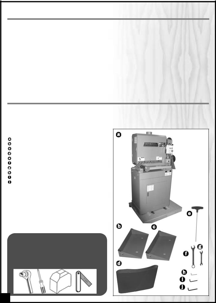
Carefully unpack and remove the sander and its components from the shipping crate and check for damaged or missing items as per the list of contents below.
Note: Please report any damaged or missing items to your General International distributor immediately.
LIST OF CONTENTS |
QTY |
SANDER .......................................................................... |
1 |
REAR EXTENSION TABLE................................................. |
1 |
SIDE EXTENSION TABLE .................................................. |
1 |
SANDING BELT* ............................................................. |
2 |
3 MM T-WRENCH* ......................................................... |
1 |
19 MM COMBINATION WRENCH*............................... |
1 |
10 - 12 MM OPEN END WRENCH* ............................... |
1 |
2 MM ALLEN KEY* ......................................................... |
1 |
5 MM ALLEN KEY* ......................................................... |
1 |
6 MM ALLEN KEY* ......................................................... |
1 |
* The sanding belts and tools are stored inside the sander cabinet to prevent damage in shipping. Open the cabinet door and remove the sanding belts and
tools from the cabinet.
*
ADDITIONAL REQUIREMENTS FOR SET UP |
|
|
|
• 11 mm Socket Wrench |
* |
||
• Phillips Screwdriver |
* |
||
• Gauge blocks (suggested) |
|
|
|
• Shims or feeler gauge set (suggested) |
* |
* |
|
|
|
|
|
|
|
|
|
|
|
|
* |
|
|
|
* |
|
|
|
|
8
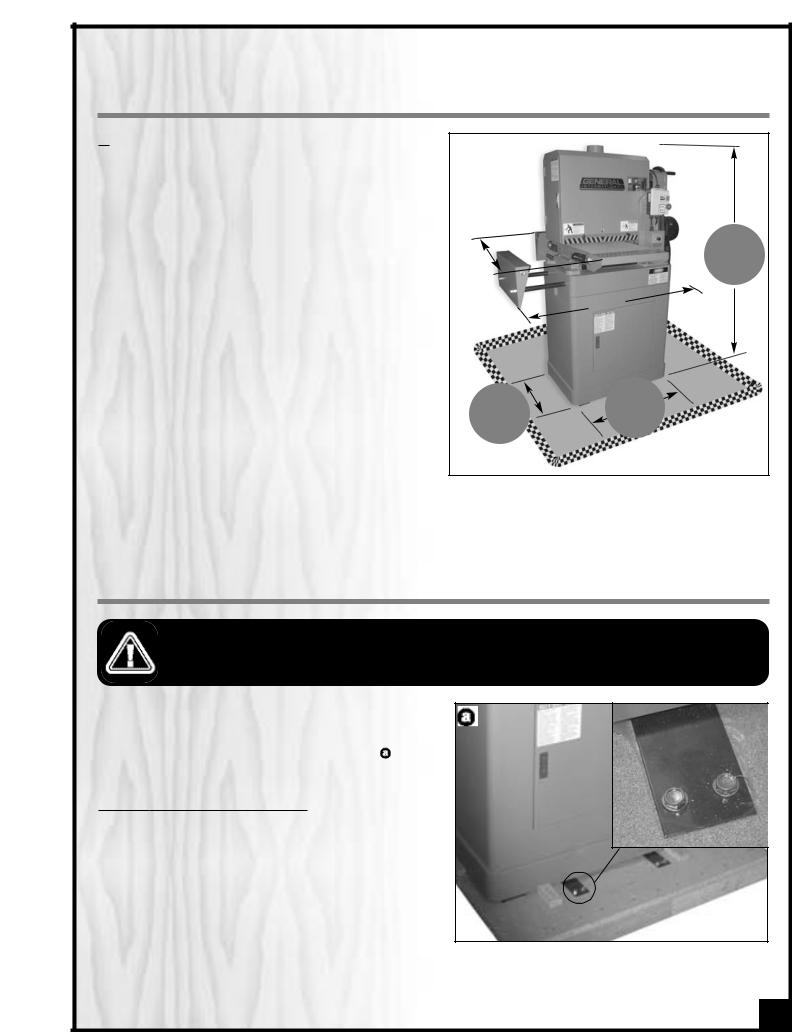
PLACEMENT WITHIN THE SHOP / ESTABLISHING A SAFETY ZONE
PLACEMENT WITHIN THE SHOP
This machine should be installed and operated only on a solid, flat and stable floor that is able to support the weight of the sander (400 lbs - 182 kg) and the operator.
Using the dimensions shown as a guideline, plan for placement within your shop that will allow the operator to work unencumbered and unobstructed by foot traffic (either passing shop visitors or other shop workers) or other tools or machinery.
ESTABLISHING A SAFETY ZONE
For shops with frequent visitors or multiple operators, it is advisable to establish a safety zone around shop machinery. A clearly defined “no-go” zone on the floor
steps to ensure that all operators and shop visitors are aware that these areas are off limits whenever a machine is running for everyone but the individual operating the unit.
52” |
64 |
|
39” |
29.5” |
18.5” |
LIFTING AND HANDLING THE MACHINE
THIS MODEL 15-030 SANDER IS VERY HEAVY.
TO LIMIT THE RISK OF SERIOUS INJURY OR DAMAGE TO THE MACHINE, READ AND FOLLOW ALL RECOMMENDATIONS BELOW.
9
 Loading...