


 Heavy duty open steel stand for greater stability.
 High quality conveyor belt for longer service life.
 Large hand wheel adjusts conveyor table height.
 Graduated depth scale in both inches and metric to indicate sanding thickness.
 Independent switches with removable safety key for both conveyor motor and main motor.
 4” dust outlet.
MAXIMUM SANDING WIDTH 13” (330 MM)
MAXIMUM SANDING THICKNESS 3 3⁄4” (95 MM)
MINIMUM SANDING THICKNESS 1⁄4” (6 MM)
MINIMUM SANDING LENGTH 5” (127 MM)
DRUM DIAMETER 5” (127 MM)
DRUM SPEED 1550 RPM
FEEDING SPEED
6 TO 20 FPM (1.8 TO 6.2 M/MIN)
MAIN MOTOR
1 1⁄2 HP, 110 V, 13 A
CONVEYOR MOTOR 1⁄15 HP
WEIGHT (WITH STAND) 298 LBS (135.4 KG)
VERSION 2_ REVISION 2 - APRIL 4, 2014 (19094510)
© COPYRIGHT GENERAL INTERNATIONAL

GENERAL® INTERNATIONAL
8360 Champ-d’Eau, Montreal (Quebec) Canada H1P 1Y3 Telephone (514) 326-1161 • Fax (514) 326-5555 • www.general.ca
THANK YOU for choosing this General® International model 15-155 13” Horizontal Single Drum Sander. This sander has been carefully tested and inspected before shipment and if properly used and maintained, will provide you with years of reliable service. To ensure optimum performance and trouble-free operation, and to get the most from your investment, please take the time to read this manual before assembling, installing and operating the unit.
The manual’s purpose is to familiarize you with the safe operation, basic function, and features of this sander as well as the set-up, maintenance and identification of its parts and components. This manual is not intended as a substitute for formal woodworking instruction, nor to offer the user instruction in the craft of woodworking. If you are not sure about the safety of performing a certain operation or procedure, do not proceed until you can confirm, from knowledgeable and qualified sources, that it is safe to do so.
Once you’ve read through these instructions, keep this manual handy for future reference.
Disclaimer: The information and specifications in this manual pertain to the unit as it was supplied from the factory at the time of printing. Because we are committed to making constant improvements, General® International reserves the right to make changes to components, parts or features of this unit as deemed necessary, without prior notice and without obligation to install any such changes on previously delivered units. Reasonable care is taken at the factory to ensure that the specifications and information in this manual corres-
ponds with that of the unit with which it was supplied. However, special orders and “after factory” modifications may render some or all information in this manual inapplicable to your machine. Further, as several generations of this model of sander and several versions of this manual may be in circulation, if you own an earlier or later version of this unit, this manual may not depict your machine exactly. If you have any doubts or questions contact your retailer or our support line with the model and serial number of your unit for clarification.

GENERAL® & GENERAL® INTERNATIONAL WARRANTY
All component parts of General®, General® International and Excalibur by General International ® products are carefully inspected during all stages of production and each unit is thoroughly inspected upon completion of assembly.
Limited Lifetime Warranty
Because of our commitment to quality and customer satisfaction, General® and General® International agree to repair or replace any part or component which upon examination, proves to be defective in either workmanship or material to the original purchaser for the life of the tool. However, the Limited Lifetime Warranty does not cover any product used for professionnal or commercial production purposes nor for industrial or educational applications. Such cases are covered by our Standard 2-year Limited Warranty only. The Limited Lifetime Warranty is also subject to the “Conditions and Exceptions” as listed below.
Standard 2-Year Limited Warranty
All products not covered by our lifetime warranty including products used in commercial, industrial and educational applications are warranted for a period of 2 years (24 months) from the date of purchase. General® and General® International agree to repair or replace any part or component which upon examination, proves to be defective in either workmanship or material to the original purchaser during this 2-year warranty period, subject to the “conditions and exceptions” as listed below.
To file a Claim
To file a claim under our Standard 2-year Limited Warranty or under our Limited Lifetime Warranty, all defective parts, components or machinery must be returned freight or postage prepaid to General® International, or to a nearby distributor, repair center or other location designated by General® International. For further details call our service department at 1-888- 949-1161 or your local distributor for assistance when filing your claim.
Along with the return of the product being claimed for warranty, a copy of the original proof of purchase and a “letter of claim” must be included (a warranty claim form can also be used and can be obtained, upon request, from General® International or an authorized distributor) clearly stating the model and serial number of the unit (if applicable) and including an explanation of the complaint or presumed defect in material or workmanship.
CONDITIONS AND EXCEPTIONS:
This coverage is extended to the original purchaser only. Prior warranty registration is not required but documented proof of purchase i.e. a copy of original sales invoice or receipt showing the date and location of the purchase as well as the purchase price paid, must be provided at the time of claim.
Warranty does not include failures, breakage or defects deemed after inspection by General® or General® International to have been directly or indirectly caused by or resulting from: improper use, or lack of or improper maintenance, misuse or abuse, negligence, accidents, damage in handling or transport, or normal wear and tear of any generally considered consumable parts or components.
Repairs made without the written consent of General® Internationallwill void all warranty.

TABLE OF CONTENTS
SAFETY RULES . . . . . . . . . . . . . . . . . . . . . . .5
ELECTRICAL REQUIREMENTS . . . . . . . . . . . . . .6
Grounding instructions . . . . . . . . . . . . . . . . . . . . . . .6 Circuit capacity . . . . . . . . . . . . . . . . . . . . . . . . . . . . .6 Extension cords . . . . . . . . . . . . . . . . . . . . . . . . . . . . .6
IDENTIFICATION OF MAIN PARTS AND COMPONENTS . . . . . . . . . . . . . . . . . . . . . . .7
BASIC FUNCTIONS . . . . . . . . . . . . . . . . . . . .8
UNPACKING . . . . . . . . . . . . . . . . . . . . . . . .8
List of contents . . . . . . . . . . . . . . . . . . . . . . . . . . . . . .8 Additional requirements for set up . . . . . . . . . . . . .9
ASSEMBLY INSTRUCTIONS . . . . . . . . . . . . . . |
9 |
Install the carrying handles . . . . . . . . . . . . . . . . . . . .9
Install the conveyor height adjustment
hand wheel . . . . . . . . . . . . . . . . . . . . . . . . . . . . . . . .9 Assemble the stand . . . . . . . . . . . . . . . . . . . . . . . . . .9
Fasten the sander to the stand or to your shop-made bench . . . . . . . . . . . . . . . . . . . . . . . . .10
CONNECTING TO A DUST COLLECTOR . . . . . . .10
BASIC ADJUSTMENTS & CONTROLS . . . . . . .11
Connecting to a power source . . . . . . . . . . . . . . .11 ON/OFF power switches . . . . . . . . . . . . . . . . . . . . .11 Drum motor ON/OFF switch . . . . . . . . . . . . . . . . . .11 Conveyor motor ON/OFF switch . . . . . . . . . . . . . .11 Raising/Lowering the conveyor table . . . . . . . . .12 Changing feed speed . . . . . . . . . . . . . . . . . . . . . .12
OPERATING INSTRUCTIONS . . . . . . . . . . . . .13
Checking before starting . . . . . . . . . . . . . . . . . . . .13 Operations step-by-step . . . . . . . . . . . . . . . . . . . . .14 To stop the machine . . . . . . . . . . . . . . . . . . . . . . . .14
CHANGING/REPLACING THE SANDING BELT . . .15
Removing the sanding belt . . . . . . . . . . . . . . . . . .15 Mounting a new sanding belt . . . . . . . . . . . . .16-18
LUBRICATION . . . . . . . . . . . . . . . . . . . . . . .18
PERIODIC MAINTENANCE . . . . . . . . . . . . . . .19
REQUIRED MAINTENANCE . . . . . . . . . . . . .19-20
RECOMMENDED OPTIONAL ACCESSORIES . . . .20
PARTS LIST AND DIAGRAMS . . . . . . . . . . .21-29

RULES FOR SAFE OPERATION
To help ensure safe operation, please take a moment to learn the machine’s applications and limitations, as well as potential hazards. General® International disclaims any real or implied warranty and holds itself harmless for any injury that may result from improper use of its equipment.
1.Do not operate the sander when tired, distracted, or under the effects of drugs, alcohol or any medication that impairs reflexes or alertness.
2.The working area should be well lit, clean and free of debris.
3.Keep children and visitors at a safe distance when the sander is in operation; do not permit them to operate the sander.
4.Childproof and tamper proof your shop and all machinery with locks, master electrical switches and switch keys, to prevent unauthorized or unsupervised use.
5.Stay alert! Give your work your undivided attention. Even a momentary distraction can lead to serious injury.
6.Fine particulate dust is a carcinogen that can be hazardous to health. Work in a well-ventilated area and wear eye, ear and respiratory protection devices.
7.Do not operate this sander without an adequate dust collection system properly installed and running. Operating this sander without adequate dust collection can lead to equipment malfunction or dangerous situations for the operator or other individuals in the workshop.
8.Do not wear loose clothing, gloves, bracelets, necklaces or other jewelry while the sander is in operation. Wear protective hair covering to contain long hair and wear non-slip footwear.
9.Be sure that adjusting wrenches, tools, drinks and other clutter are removed from the machine and/or the feed table surface before operating.
10.Keep hands well away from the sanding belts and all moving parts. Use a brush, not hands, to clear away sanding dust.
11.Be sure sanding belts are securely installed on the sanding drums.
12.Do not operate the sander if the sanding belts are damaged or badly worn.
13.Do not push or force the workpiece into the sander. The machine will perform better and more safely when working at the feed rate for which it was designed.
14.Avoid working from awkward or off balance positions. Do not overreach and keep both feet on floor.
15.To minimize risk of injury in the event of workpiece kickback, never stand directly in-line with the sanding belt or in the potential kickback path of the work piece.
16.Keep guards in place and in working order. If a guard must be removed for maintenance or cleaning, be sure it is properly re-attached before using the tool again.
17.Never leave the machine unattended while it is running or with the power on.
18.Use of parts and accessories NOT recommended by GENERAL→ INTERNATIONAL may result in equipment malfunction or risk of injury.
19.Never stand on the machine. Serious injury could occur if the sander is tipped over or if the sanding belt is unintentionally contacted.
20.Always disconnect the tool from the power source before servicing, changing accessories or sanding belts, or before performing any maintenance or cleaning, or if the machine will be left unattended.
21.Make sure that switch is in “OFF” position before plugging in the power cord.
22.Make sure the tool is properly grounded. If equipped with a 3-prong plug it should be used with a three-pole receptacle. Never remove the third prong.
23.Do not use the sander for other than its intended use. If used for other purposes, GENERAL→ INTER NATIONAL disclaims any real implied warranty and holds itself harmless for any injury, which may result from that use.
5
ELECTRICAL REQUIREMENTS
BEFORE CONNECTING THE MACHINE TO THE POWER SOURCE, VERIFY THAT THE VOLTAGE OF YOUR POWER SUPPLY CORRESPONDS WITH THE VOLTAGE SPECIFIED ON THE MOTOR I.D. NAMEPLATE. A POWER SOURCE WITH GREATER VOLTAGE THAN NEEDED CAN RESULT IN SERIOUS INJURY TO THE USER AS WELL AS DAMAGE TO THE MACHINE. IF IN DOUBT, CONTACT A QUALIFIED ELECTRICIAN BEFORE CONNECTING TO THE POWER SOURCE.
THIS TOOL IS FOR INDOOR USE ONLY. DO NOT EXPOSE TO RAIN OR USE IN WET OR DAMP LOCATIONS.
A
B C
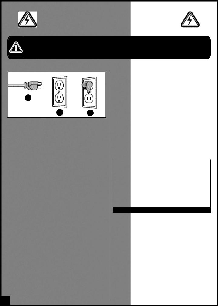
GROUNDING INSTRUCTIONS
In the event of an electrical malfunction or short circuit, grounding reduces the risk of electric shock. The motor of this machine is wired for 110V single phase operation and is equipped with a 3-conductor cord and a 3- prong grounding plug A to fit a grounded type receptacle B. Do not remove the 3rd prong (grounding pin) to make it fit into an old 2-hole wall socket or extension cord. If an adaptor plug is used C, it must be attached to the metal screw of the receptacle.
Note: The use of an adaptor plug is illegal in some areas. Check your local codes. If you have any doubts or if the supplied plug does not correspond to your electrical outlet, consult a qualified eletrician before proceeding.
CIRCUIT CAPACITY
Make sure that the wires in your circuit are capable of handling the amperage draw from your machine, as well as any other machines that could be operating on the same circuit. If you are unsure, consult a qualified electrician. If the circuit breaker trips or the fuse blows regularly, your machine may be operating on a circuit that is close to its amperage draw capacity. However, if an unusual amperage draw does not exist and a power failure still occurs, contact a qualified technician or our service department.
EXTENSION CORDS
If you find it necessary to use an extension cord with your machine, use only 3-wire extension cords that have 3- prong grounding plug and a matching 3-pole receptacle that accepts the tool’s plug. Repair or replace a damaged extension cord or plug immediately.
Make sure the cord rating is suitable for the amperage listed on the motor I.D. plate. An undersized cord will cause a drop in line voltage resulting in loss of power and overheating. The accompanying chart shows the correct size extension cord to be used based on cord length and motor I.D. plate amp rating. If in doubt, use the next heavier gauge. The smaller the number, the heavier the gauge.
AMPERES |
EXTENSION CORD LENGTH |
|||
(AMPS) |
25 FEET |
50 FEET |
100 FEET |
150 FEET |
|
|
|
|
|
< 5 |
18 |
16 |
16 |
14 |
6 TO 10 |
18 |
16 |
14 |
12 |
10 TO 12 |
16 |
16 |
14 |
14 |
12 TO 16 |
14 |
12 |
* NR |
* NR |
|
|
|
|
|
* NR = Not Recommended
6
13” HORIZONTAL SINGLE DRUM SANDER |
|
||
15-155 M1 |
|
|
|
IDENTIFICATION OF MAIN PARTS AND COMPONENTS |
|
||
H |
B |
C |
|
A |
|
E |
|
|
|
||
|
|
D |
|
K |
|
F |
|
|
|
I |
|
G |
|
|
|
|
|
J |
|
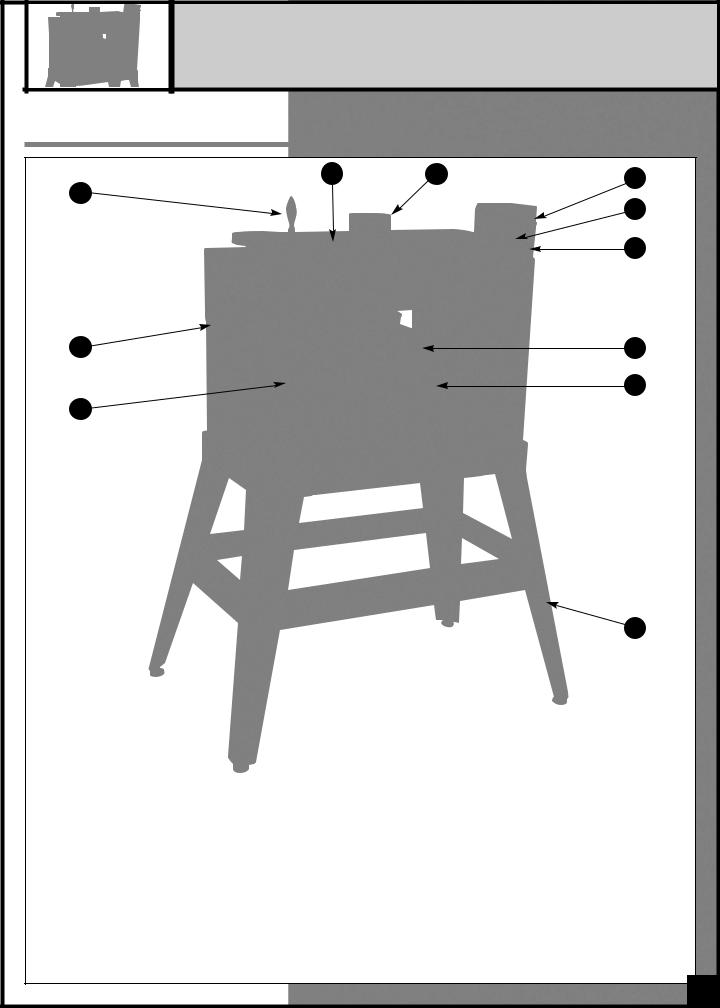
A - CONVEYOR TABLE HEIGHT |
F - CONVEYOR BELT |
|
|
ADJUSTMENT HAND WHEEL |
G - GRADUATED DEPTH SCALE |
|
|
B - DUST OUTLET |
|
||
H - SANDING DRUM (UNDER DRUM COVER) |
|||
C - CONVEYOR MOTOR START/STOP |
|||
I - CONVEYOR TABLE |
|
||
SWITCH WITH SAFETY KEY |
|
||
J - OPEN STAND |
|
||
D - CONVEYOR BELT SPEED |
|
||
K - CARRYING HANDLE |
|
||
ADJUSTING KNOB |
|
||
E - SANDING DRUM MOTOR |
|
|
|
POWER SWITCH |
|
|
|
|
|
7 |
|
BASIC FUNCTIONS
This drum sander is designed for surface sanding of flat wooden panels, glue-ups and other natural wood products, having a minimum length of 5” and up to a maximum width of 13”. The minimum/maximum capacity (workpiece thickness range), is from 1/4” up to 3 3/4”. This sander is not intended (and should not be used) to sand any material other than wood.
BASIC PRINCIPLES OF SANDING
It is always preferable to remove less material per pass and take multiple passes. This can extend sanding belt life, place less strain on the motor and provide better workpiece finish quality.
DO NOT USE THIS SANDER AS A THICKNESS PLANER. NEVER ATTEMPT TO REMOVE MORE THAN THE DEPTH OF THE GRAIN OF THE SANDING BELT IN ANY SINGLE PASS. TOO MUCH FRICTION WILL CAUSE BELT TO OVERHEAT AND WEAR PREMATURELY, AND, IN EXTREME CASES, MAY CAUSE BURNS IN THE WORKPIECE.
Note: To avoid overworking the motor, creating a potential circuit overload, or damaging the sanding drum, do not force the workpiece against or into the drum. For better finish results and to avoid potential damage to the sander or the workpiece, let the workpiece feed into the sander at the rate of feed to which the conveyer is set.
Note: As with any other drum or belt sander, depending on the final finish quality you require, some final hand sanding may be required.
UNPACKING
Carefully unpack and remove the sander and its components from the shipping crate and check for damaged or missing items as per the list of contents below.
Note: Please report any damaged or missing items to your General International distributor immediately.
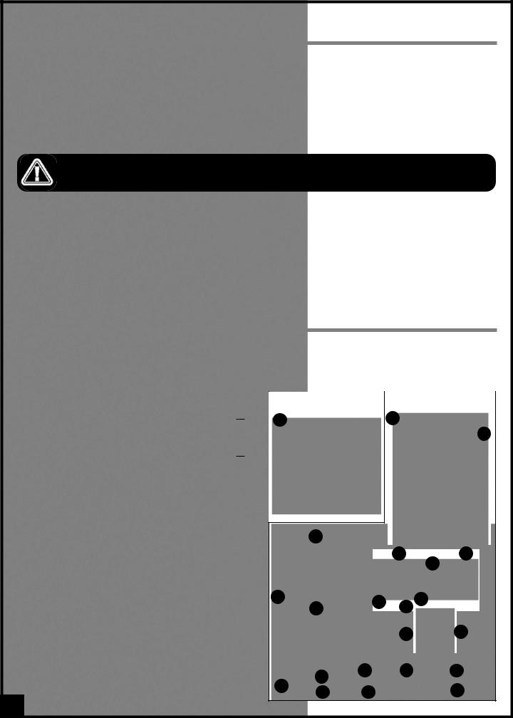
LIST OF CONTENTS |
|
|
BOX 1 - SANDER |
QTY |
|
A - |
13” HORIZONTAL SINGLE DRUM SANDER |
.....................1 |
BOX 2 - OPEN STAND & OTHER COMPONENTS |
QTY |
|
B - |
LONG TOP SHELF ........................................................... |
2 |
C - |
LONG CROSS BRACE .................................................... |
2 |
D - |
SUPPORT LEG ................................................................. |
4 |
E - |
SHORT TOP SHELF........................................................... |
2 |
F - |
SHORT CROSS BRACE.................................................... |
2 |
HARDWARE BAG INCLUDING: |
|
|
G - |
HAND WHEEL............................................................................. |
1 |
H - |
HAND WHEEL HANDLE.............................................................. |
1 |
I - |
5 MM ALLEN KEY ...................................................................... |
1 |
J - |
6 MM T-HANDLE ALLEN WRENCH ............................................ |
1 |
K - |
2 MM T-HANDLE ALLEN WRENCH ............................................ |
1 |
L - |
1214 MM OPEN END WRENCH.............................................. |
1 |
M - CARRYING HANDLE .................................................................. |
2 |
|
N - |
CAP SCREW............................................................................... |
4 |
O - |
LEVELING FOOT ............................................................. |
4 |
P - |
FLAT WASHER.................................................................. |
8 |
Q - |
HEX NUT ......................................................................... |
8 |
R - |
SHOULDER BOLT........................................................... |
16 |
S - |
HEX NUT ....................................................................... |
16 |
T - |
LOCK WASHER ............................................................. |
20 |
U - |
FLAT WASHER................................................................ |
20 |
V - |
CAP SCREW ................................................................... |
4 |
|
BOX 1 |
BOX 2 |
|
|
A |
B |
|
C
E
J G
H
D K I
F L
M N
R T U
P
O
Q S V
8

ADDITIONAL REQUIREMENTS FOR SET UP
•Extra person for help with lifting
•Phillips Screwdriver
•Utility knife
•Flat piece of wood or any similar non-cutting object
ASSEMBLY INSTRUCTIONS
SERIOUS PERSONAL INJURY COULD OCCUR IF YOU CONNECT THE MACHINE TO THE POWER SOURCE BEFORE YOU HAVE COMPLETED THE INSTALLATION AND ASSEMBLY STEPS. DO NOT CONNECT THE MACHINE TO THE POWER SOURCE UNTIL INSTRUCTED TO DO SO.
INSTALL THE CARRYING HANDLES
B
A
Install the carrying handles A on both sides of the sander using 2 cap screws B and tighten with the supplied 6 mm T-handle allen wrench.
Note: Do not lift the sander by the conveyor table. Always use the carrying handles to lift or carry the sander.
INSTALL THE CONVEYOR HEIGHT ADJUSTMENT HAND WHEEL
BA
C
1.Screw the handle C into the threaded hole in the hand wheel.
2.Install the conveyor table height adjustment hand wheel onto the shaft located on the top left end of the sander B. The slots in the hand wheel must be aligned with the spring pin on the shaft A.
ASSEMBLE THE STAND
Note: If the sander is to be used without our supplied stand, then the following instructions do not apply – please skip ahead to the next section on page 10.
1.With the 16 shoulder bolts, washers, lock washers and hex nuts, A, begin assembling one end of the sander stand by attaching 1 short top shelf and 1 short cross brace to 2 legs, B.
Note: Do not tighten hex nuts until all fasteners are atta-ched. Then place the stand on a flat surface to square it up and finally tighten all the nuts.
2.Assemble the opposite side of the stand the same way as described in step 1. Then use the 2 long top shelves and 2 long cross braces to join both assembled ends and complete the stand as shown in C on next page.
A |
Short top shelf |
|
|
|
Legs |
|
B |
|
Short cross brace |
(Be sure to attach all horizontal shelves and cross braces to the insides of stand legs.)
9
 Loading...