


50-200R

SETUP & OPERATION MANUAL
FEATURES
Combination riving style splitter and seethrough blade guard with anti-kickback
pawls, and a second European style riving knife also included.
Large precision-ground 44” x 27” cast-iron
table with two extension wings.
4” dust port allows easy connection to a
dust collection system.
Large paddle-style stop switch.
Ruggedly built saw carriage with solid
cast-iron cabinet mounted trunnions.
Large motor access door for quick clean-
ing and easier maintenance.
Convenient arbor lock for fast one tool
blade changes.
Equipped with a sturdy, easy to adjust, T-
fence design rip fence system.
Powerful 2 HP motor with multi-groove V-
belt drive for longer belt life and more efficient transfer of power.
Onboard storage mounts for wrench, rip
fence and miter gauge.
Dual voltage motor factory wired for 230V
operation.
10" LEFT TILT 2 HP TABLE SAW
SPECIFICATIONS
BLADE DIAMETER
10” (254 MM)
ARBOR DIAMETER
5/8" (16 MM)
ARBOR TILT RANGE
0° À 45° (TO LEFT)
MAXIMUM DEPTH OF CUT AT 90°
3” (77 mm)
MAXIMUM DEPTH OF CUT AT 45°
2 1/4” (54 MM)
MAX. RIP TO RIGHT OF BLADE
30” (762 MM)
MAX. RIP TO LEFT OF BLADE
8” (203 MM)
DADO CAPACITY
13/16” (21 MM)
DUST PORT DIAMETER
4" (102 MM)
ARBOR SPEED
4000 RPM
TABLE HEIGHT
36” (914 MM)
TABLE SIZE (W/EXTENSION WINGS)
44” X 27” (1118 X 686 MM)
TABLE SIZE (W/O EXTENSION WINGS)
20” X 27” (508 X 686 MM)
BASE DIMENSIONS (L X W)
20” X 20” (508 X 508 MM)
MOTOR (PRE-WIRED 230V)
2 HP, 115/230V 19.5/9.5 A
WEIGHT
321 LBS (146 KG)
MODEL
#50-200R
VERSION 3_REVISION 1 - JUNE 29/11
© Copyright General® International 06/2011

GENERAL® INTERNATIONAL
8360 Champ-d’Eau, Montreal (Quebec) Canada H1P 1Y3
Telephone (514) 326-1161 • Fax (514) 326-5555 • www.general.ca
THANK YOU for choosing this General
®
International model 50-200R 10" Left tilt
2 HP Table Saw.This saw has been carefully tested and inspected before shipment and if properly used and maintained, will provide you with years of reliable service. For your safety, as well
as to ensure optimum performance and trouble-free operation, and to get the most from your
investment, please take the time to read this manual before assembling, installing and operating the unit.
The manual’s purpose is to familiarize you with the safe operation, basic function, and features
of this saw as well as the set-up, maintenance and identification of its parts and components.
This manual is not intended as a substitute for formal woodworking instruction, nor to offer the
user instruction in the craft of woodworking. If you are not sure about the safety of performing
a certain operation or procedure, do not proceed until you can confirm, from knowledgeable
and qualified sources, that it is safe to do so.
Once you’ve read through these instructions, keep this manual handy for future reference.
Disclaimer: The information and specifications in this
manual pertain to the unit as it was supplied from the
factory at the time of printing. Because we are committed to making constant improvements, General
International reserves the right to make changes to
components, parts or features of this unit as deemed
necessary,without prior notice and without obligation to
install any such changes on previously delivered units.
Reasonable care is taken at the factory to ensure that
the specifications and information in this manual corres-
ponds with that of the unit with which it was supplied.
However, special orders and “after factory” modifications may render some or all information in this manual
®
inapplicable to your machine. Further, as several generations of this model of saw and several versions of this
manual may be in circulation, if you own an earlier or
later version of this unit, this manual may not depict your
machine exactly. If you have any doubts or questions
contact your retailer or our support line with the model
and serial number of your unit for clarification.

GENERAL®MFG & GENERAL®INTERNATIONAL WARRANTY
ll component parts of General® MFG, General® International and Excalibur by General
A
International ® products are carefully inspected during all stages of production and each unit
is thoroughly inspected upon completion of assembly.
Limited Lifetime Warranty
Because of our commitment to quality and customer satisfaction, General® MFG and
General® International agree to repair or replace any part or component which upon examination, proves to be defective in either workmanship or material to the original purchaser
for the life of the tool. However, the Limited Lifetime Warranty does not cover any product used
for professional or commercial production purposes nor for industrial or educational applications. Such cases are covered by our Standard 2-year Limited Warranty only. The Limited
Lifetime Warranty is also subject to the “Conditions and Exceptions” as listed below.
Standard 2-Year Limited Warranty
All products not covered by our lifetime warranty including products used in commercial,
industrial and educational applications are warranted for a period of 2 years (24 months) from
the date of purchase. General® MFG and General® International agree to repair or replace
any part or component which upon examination, proves to be defective in either workmanship or material to the original purchaser during this 2-year warranty period, subject to the
“conditions and exceptions” as listed below.
To file a Claim
To file a claim under our Standard 2-year Limited Warranty or under our Limited Lifetime
Warranty, all defective parts, components or machinery must be returned freight or postage
prepaid to General® International, or to a nearby distributor, repair center or other location
designated by General® International. For further details call our service department at 1-888949-1161 or your local distributor for assistance when filing your claim.
Along with the return of the product being claimed for warranty, a copy of the original proof
of purchase and a “letter of claim” must be included (a warranty claim form can also be used
and can be obtained, upon request, from General® International or an authorized distributor)
clearly stating the model and serial number of the unit (if applicable) and including an explanation of the complaint or presumed defect in material or workmanship.
CONDITIONS AND EXCEPTIONS:
This coverage is extended to the original purchaser only. Prior warranty registration is not
required but documented proof of purchase i.e. a copy of original sales invoice or receipt
showing the date and location of the purchase as well as the purchase price paid, must be
provided at the time of claim.
Warranty does not include failures,breakage or defects deemed after inspection by General®
MFG or General® International to have been directly or indirectly caused by or resulting from;
improper use, or lack of or improper maintenance, misuse or abuse, negligence, accidents,
damage in handling or transport, or normal wear and tear of any generally considered consumable parts or components.
Repairs made without the written consent of General® Internationallwill void all warranty.

TABLE OF CONTENTS
SAFETY RULES . . . . . . . . . . . . . . . . . . . . . . .5
ELECTRICAL REQUIREMENTS . . . . . . . . . . . . . .6
Grounding instructions . . . . . . . . . . . . . . . . . . . . . . .6
Circuit capacity . . . . . . . . . . . . . . . . . . . . . . . . . . . . .6
Converting the motor to 115V . . . . . . . . . . . . . . . . .6
Extension cords . . . . . . . . . . . . . . . . . . . . . . . . . . . . .6
IDENTIFICATION OF MAIN PARTS AND
COMPONENTS . . . . . . . . . . . . . . . . . . . . . . .
BASIC FUNCTIONS . . . . . . . . . . . . . . . . . . . .8
UNPACKING . . . . . . . . . . . . . . . . . . . . . . . .8
List of contents . . . . . . . . . . . . . . . . . . . . . . . . . . . . . .8
Additional requirements for set up . . . . . . . . . . . . .8
PLACEMENT WITHIN THE SHOP / ESTABLISHING A
SAFETY ZONE . . . . . . . . . . . . . . . . . . . . . . . .
CLEAN UP . . . . . . . . . . . . . . . . . . . . . . . . . .9
ASSEMBLY INSTRUCTIONS . . . . . . . . . . . . . .10
Install the table exension wings . . . . . . . . . . . . . .10
Install the handwheels . . . . . . . . . . . . . . . . . . . . . .10
Mount the rip fence storage brackets . . . . . . . . .10
Mount the miter gauge & wrench . . . . . . . . . . . . .10
Install the rear fence rail . . . . . . . . . . . . . . . . . . . . .10
Install the front fence rail . . . . . . . . . . . . . . . . . . . .11
Mount the switch . . . . . . . . . . . . . . . . . . . . . . . . . . .11
Install / remove a saw blade . . . . . . . . . . . . .12
Install a saw blade . . . . . . . . . . . . . . . . . . . . . . . . .12
To remove a saw blade . . . . . . . . . . . . . . . . . . . . .12
Align the rip fence 90º to the table . . . . . . . . . . . .14
Install the measuring tape & pointer . . . . . . .15
Connecting to a dust collector . . . . . . . . . . .16
BASIC ADJUSTMENTS AND CONTROLS . . . . . .16
Connecting to a power source . . . . . . . . . . . . . . .16
ON / OFF switch and safety pin . . . . . . . . . . . . . . .17
7
Blade height & tilt adjustment . . . . . . . . . . . .17
Blade height adjustment . . . . . . . . . . . . . . . . . . . .17
Blade tilt (bevel) adjustment . . . . . . . . . . . . . . . . .17
OPERATING INSTRUCTIONS . . . . . . . . . . . . .18
Types of cuts . . . . . . . . . . . . . . . . . . . . . . .18
Ripping . . . . . . . . . . . . . . . . . . . . . . . . . . . . . . . . . . .18
Bevel ripping . . . . . . . . . . . . . . . . . . . . . . . . . . . . . .19
Ripping small work pieces . . . . . . . . . . . . . . . . . . .19
9
Cross cutting . . . . . . . . . . . . . . . . . . . . . . . . . . . . . . .19
Bevel cross cutting . . . . . . . . . . . . . . . . . . . . . . . . . .19
Adjusting and using the miter gauge . . . . . . .19
Adding an auxiliary fence to the miter gauge . .20
Miter cuts . . . . . . . . . . . . . . . . . . . . . . . . . . . . . . . . . .20
Compound miter cuts . . . . . . . . . . . . . . . . . . . . . . .20
Using a dado head blade . . . . . . . . . . . . . . .20
MAINTENANCE & ADJUSTMENTS . . . . . . . . . .21
Periodic maintenance . . . . . . . . . . . . . . . . . . . . . .21
Lubrication . . . . . . . . . . . . . . . . . . . . . . . . . . . . . . . .21
Adjusting the 45 º & 90 º bevel stops . . . . . . . . . . .21
Adjusting the bevel angle pointer . . . . . . . . . . . .22
Install and adjust riving knife . . . . . . . . . . . .13
Select a riving knife . . . . . . . . . . . . . . . . . . . . . . . . .13
Removal/Installation . . . . . . . . . . . . . . . . . . . . . . . .13
Level the table insert . . . . . . . . . . . . . . . . . .13
Align the rip fence . . . . . . . . . . . . . . . . . . . .14
Align the rip fence parallel to the blade . . . . . . .14
Recommended optional accessories . . . . .23
Parts list and diagrams . . . . . . . . . . .24 - 31

RULES FOR SAFE OPERATION
To help ensure safe operation, please take a moment to learn the machine’s applications and limitations, as well as potential hazards. General® International disclaims any real or implied warranty and holds itself harmless for any injury that
ay result from improper use of its equipment.
m
1. Do not operate the saw when tired, distracted, or
nder the effects of drugs, alcohol or any medica-
u
tion that impairs reflexes or alertness.
2. The working area should be well lit, clean and free
of debris.
3. Keep children and visitors at a safe distance when
the saw is in operation; do not permit them to
operate the saw.
4. Childproof and tamper proof your shop and all
machinery with locks, master electrical switches
and switch keys, to prevent unauthorized or unsupervised use.
5. Stay alert! Give your work your undivided atten-
tion. Even a momentary distraction can lead to serious injury.
6. Fine particulate dust is a carcinogen that can be
hazardous to health. Work in a well-ventilated area
and whenever possible use a dust collector and
wear eye, ear and respiratory protection devices.
7. Do not wear loose clothing, gloves, bracelets, neck-
laces or other jewelry while the saw is in operation.
Wear protective hair covering to contain long hair
and wear non-slip footwear.
8. Be sure that adjusting wrenches, tools, drinks and
other clutter are removed from the machine and/or
the table surface before operating.
9. Keep hands well away from the blade and all mo-
ving parts. Use a brush, not hands, to clear away
chips and dust.
10. Be sure that the blade is securely installed and in
proper cutting direction before operation.
11. Be sure the blade has gained full operating speed
before beginning to cut.
12. Always use a clean, properly sharpened blade.
Dirty or dull blades are unsafe and can lead to
accidents.
13. If using a power feeder,stop the feeder before stop-
ping the table saw.
15. Use suitable support when cutting stock that does
ot have a flat surface. Always hold stock firmly
n
against the fence when ripping, or against the miter
gauge when cross-cutting.
16. To minimize risk of injury in the event of workpiece
kickback, never stand directly in-line with the blade
or in the potential kickback path of the work piece.
17. Avoid working from awkward or off balance posi-
tions. Do not overreach while cutting; keep both
feet on floor. Never lean over or reach over the
blade and never pull the work piece over the blade
from behind. Use out feed support or have an assistant help when ripping long material.
18. Keep blade guards in place and in working order.
If a guard must be removed for maintenance or
cleaning, be sure it is properly reattached before
using the tool again.
19. Never leave the machine running with the power
on when not in operation.
20. Use of parts and accessories NOT recommended
by
GENERAL INTERNATIONAL
ment malfunction or risk of injury.
21. Never stand on machinery. Serious injury could
result if the tool is tipped over or if the blade is unintentionally contacted.
22. Always disconnect tool from power before servicing
or changing accessories such as blades, or before
performing any maintenance, cleaning or adjustments, or if the machine will be left unattended.
23. Make sure that switch is in "OFF" position before
plugging in the power cord.
24. Make sure the tool is properly grounded. If equip-
ped with a 3-prong plug it should be used with a
three-pole receptacle. Never remove the third
prong.
25. Do not use this saw for other than its intended use. If
used for other purposes,
disclaims any real implied warranty and holds itself
harmless for any injury, which may result from that
use.
may result in equip-
GENERAL INTERNATIONAL
14. Do not push or force stock into the blade. The saw
will perform better and more safely when working
at the rate for which it was designed.
5

ELECTRICAL REQUIREMENTS
BEFORE CONNECTING THE MACHINE TO THE POWER SOURCE, VERIFY THAT THE VOLTAGE OF YOUR POWER SUPPLY CORRESPONDS
ITH THE VOLTAGE SPECIFIED ON THE MOTOR I.D. NAMEPLATE. A POWER SOURCE WITH GREATER VOLTAGE THAN NEEDED CAN
W
RESULT IN SERIOUS INJURY TO THE USER AS WELL AS DAMAGE TO THE MACHINE. IF IN DOUBT, CONTACT A QUALIFIED ELECTRICIAN
EFORE CONNECTING TO THE POWER SOURCE.
B
THIS TOOL IS FOR INDOOR USE ONLY. DO NOT EXPOSE TO RAIN OR USE IN WET OR DAMP LOCATIONS.
CONVERTING THE MOTOR TO 115V
hould you need to convert your machine’s motor from
S
C
A
B
230V to 115V power, there is an electrical schematic
drawing on the inside of the motor cover plate. Unless
you are a qualified electrician, we do not recommend
attempting this conversion on your own. If you choose
to do so, you may risk serious personal injury, damage
to the motor and voiding the warranty of your machine.
We suggest you ask your local General International
distributor to recommend qualified electricians in your
area (or perhaps one of their own technicians) who
can make this conversion properly and safely.
GROUNDING INSTRUCTIONS
In the event of an electrical malfunction or short circuit,
grounding reduces the risk of electric shock to the operator. The motor of this machine is wired for 230V single
phase operation and is equipped with a 3-conductor
cord A and a 3-prong grounded plug B to fit a matching grounding type receptacle C.
DO NOT MODIFY THE PLUG PROVIDED ! If it will not fit your recepta-
cle, have the proper receptacle installed by a qualified electrician.
CHECK with a qualified electrician or service person if
you do not completely understand these grounding
instructions, or if you are not sure the tool is properly
grounded.
CIRCUIT CAPACITY
Make sure that the wires in your circuit are capable of
handling the amperage draw from your machine, as
well as any other machines that could be operating on
the same circuit. If you are unsure, consult a qualified
electrician. If the circuit breaker trips or the fuse blows
regularly, your machine may be operating on a circuit
that is close to its amperage draw capacity. However, if
an unusual amperage draw does not exist and a
power failure still occurs, contact a qualified technician
or our service department.
EXTENSION CORDS
If you find it necessary to use an extension cord with your
machine, use only 3-wire extension cords that have 3prong grounding plug and a matching 3-pole receptacle that accepts the tool’s plug. Repair or replace a
damaged extension cord or plug immediately.
Make sure the cord rating is suitable for the amperage
listed on the motor I.D. plate. An undersized cord will
cause a drop in line voltage resulting in loss of power
and overheating. The accompanying chart shows the
correct size extension cord to be used based on cord
length and motor I.D. plate amp rating. If in doubt, use
the next heavier gauge. The smaller the number, the
heavier the gauge.
TABLE - MINIMUM GAUGE FOR CORD
TOTAL LENGTH OF CORD IN FEET
AMPERE
RATING
6 TO 10
10 TO 12
12 TO 16
* NR = Not Recommended
115 VOLTS 25 FEET 50 FEET 100 FEET 150 FEET
230 VOLTS 50 FEET 100 FEET 200 FEET 300 FEET
AWG
< 5
------->
------->
------->
------->
18 16 16 14
18 16 14 12
16 16 14 12
14 12 * NR * NR
6
10" LEFT TILT 2 HP TABLE SAW
50-200R
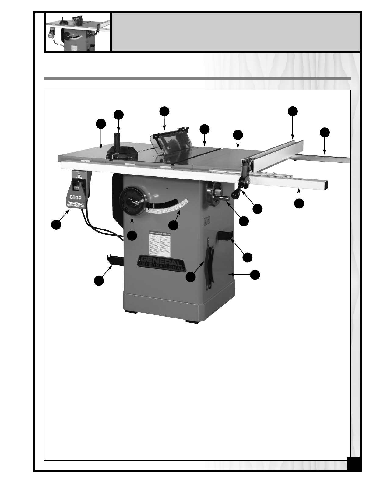
IDENTIFICATION OF MAIN PARTS AND COMPONENTS
Q
B
A
O
P
C
D
N
M
E
I
J
K
L
F
G
H
A- LEFT TABLE EXTENSION
B- MITER GAUGE
C- SPLITTER AND BLADE GUARD ASSEMBLY
D- MAIN TABLE
E- RIGHT TABLE EXTENSION
F- RIP FENCE
G- REAR RAIL
H- FRONT RAIL
I- RIP FENCE LOCKING HANDLE
J- BLADE TILT ADJUSTMENT HANDWHEEL
K- MITER GAUGE STORAGE BRACKET
L- CABINET
M- ARBOR WRENCH STORAGE BRACKET
N- BEVEL SCALE
O- BLADE HEIGHT ADJUSTMENT HANDWHEEL
P- FENCE STORAGE BRACKET
Q- ON/OFF SWITCH
7
BASIC FUNCTIONS
This saw has been designed for cutting solid wood as well as manufactured wood materials such as plywood,wood
panelling, particleboard, mdf and other wood based by-products. This saw is not designed for cutting metals nor
for cutting any materials other than wood or wood based stock.
This saw is designed for use with maximum 10" (250mm) diameter blades having a center hole diameter of 5/8".
The blade can be raised to cut a maximum stock thickness of 3" with the blade set 90 degrees to the table. The
blade can be tilted up to 45 degrees to the left for bevel cuts to a maximum stock thickness of 2 1/4". Using any
standard aftermarket 8" diameter stacked dado blade set (not included), the maximum dado cutting capacity of
this saw is 13/16" (21 mm). Note: for safer dado cutting, an optional dado table insert (part number #50-202) can
e purchased through your General International distributor.
b
The 50-200R is supplied with both a riving style splitter/blade guard assembly and a European style riving knife that
are both designed to raise or lower and tilt with the blade, and maintain a consistent distance to the blade at all
imes, regardless of the height or angle of the blade. This can help reduce (but not totally eliminate) the risk of a
t
kickback incident, where the workpiece is thrown back at the operator, by helping to prevent the workpiece from
getting stuck between the blade and the riving style splitter or riving knife (as compared to a traditional stationary
splitter) or from closing up on the back of the blade as it passes through the cut.
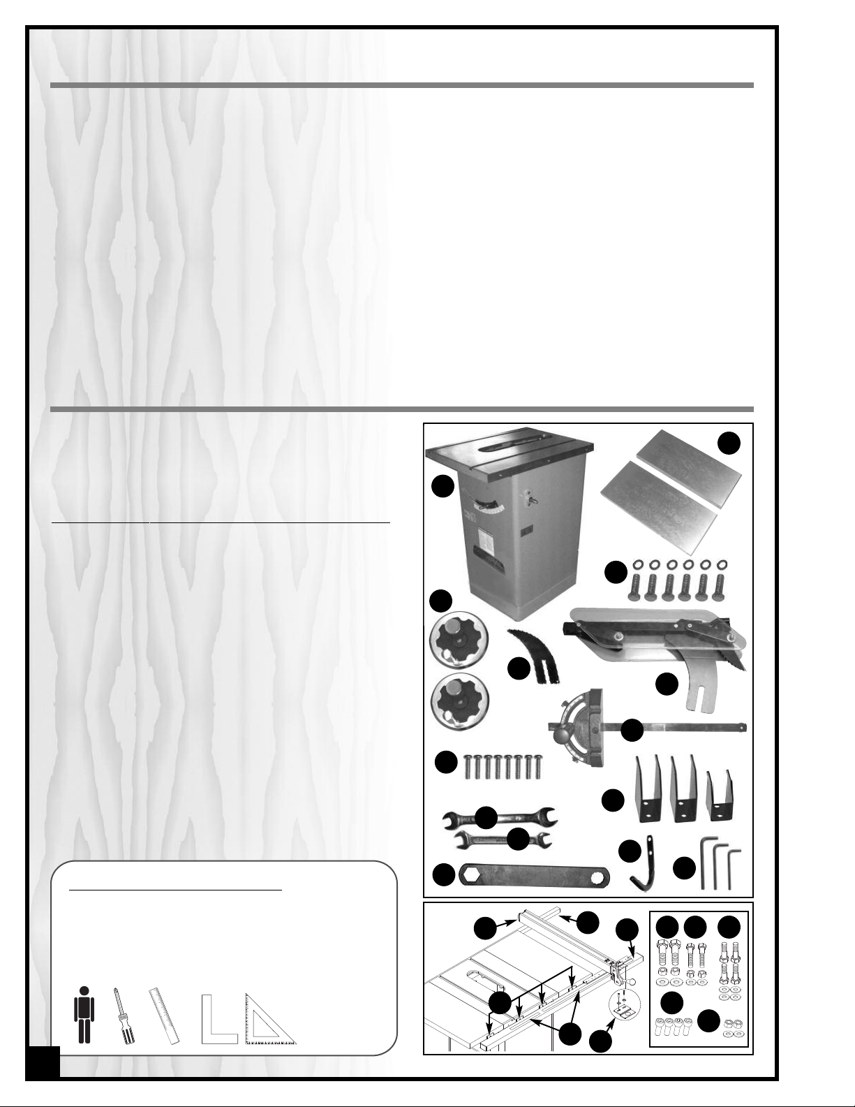
UNPACKING
Carefully unpack and remove the saw and its components from the box and check for damaged or missing
items as per the list of contents below.
NOTE: Please report any damaged or missing items to your
General® International distributor immediately.
LIST OF CONTENTS QTY
SAW ..................................................................................................1
A -
TABLE EXTENSION ............................................................................2
B -
17 MM HEX HEAD BOLT W/WASHER ..............................................6
C -
HANDWHEEL W/LOCK KNOB..........................................................2
D -
EUROPEEN STYLE RIVING KNIFE ......................................................1
E -
COMBINATION RIVING STYLE SPLITTER & BLADE GUARD..............1
F -
MITER GAUGE ..................................................................................1
G -
PHILLIPS HEAD SCREW.....................................................................8
H -
I-14-17 MM OPEN END WRENCH......................................................1
10-12 MM OPEN END WRENCH......................................................1
J -
ARBOR WRENCH .............................................................................1
K -
MITER GAUGE/RIP FENCE STORAGE BRACKET ..............................3
L -
ARBOR WRENCH STORAGE BRACKET.............................................1
M -
ALLEN KEY (6-4-3 MM,1 EACH).......................................................3
N -
T-FENCE ............................................................................................1
O -
REAR RAIL.........................................................................................1
P -
FRONT RAIL ......................................................................................1
Q -
“L” BRACKET......................................................................................4
R -
MEASURING TAPE (LEFT & RIGHT) ...................................................1
S -
FENCE POINTER/VISOR & HARDWARE ..........................................1
T -
12 MM HEX HEAD BOLT W/HEX NUT & FLAT WASHER ...................2
U -
LONG 10 MM HEX HEAD BOLT W/HEX NUT & FLAT WASHER........2
V -
SHORT 10 MM HEX HEAD BOLT W/FLAT WASHER ..........................4
W -
6 MM SOCKET CAP SCREW............................................................4
X -
12 MM HEX NUT & FLAT WASHER....................................................2
Y -
ADDITIONAL REQUIREMENTS FOR SET UP
• Extra person for help with lifting
• Phillips Screwdriver
• Straightedge
• Machinist square or triangle square
B
A
C
D
E
F
G
H
L
I
J
M
K
0
P
Q
N
U V
W
or
R
X
Y
S
T
8
PLACEMENT WITHIN THE SHOP /
ESTABLISHING A SAFETY ZONE
HIS MODEL 50-200R 10" LEFT TILT 2 HP TABLE SAW IS HEAVY. DO NOT OVER-EXERT. A HOIST OR FORKLIFT WITH STRAPS
T
HOULD BE USED TO LIFT THIS MACHINE.
S
O LIMIT THE RISK OF SERIOUS INJURY OR DAMAGE TO THE MACHINE, ANY EQUIPMENT USED TO LIFT THIS MACHINE
T
HOULD HAVE A RATED CAPACITY IN EXCESS OF 303 LBS (138KG).
S
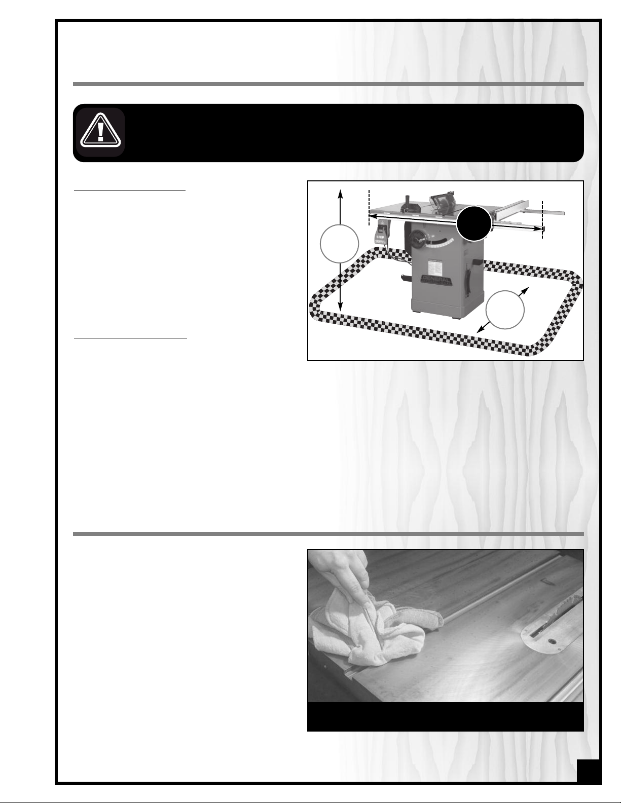
PLACEMENT WITHIN THE SHOP
This machine should be installed and operated
only on a solid, flat and stable floor that is able
to support the weight of the saw (320 Lbs - 146
kg) and the operator.
Using the dimensions shown as a guideline, plan
for placement within your shop that will allow
the operator to work unencumbered and unobstructed by foot traffic (either passing shop visitors or other shop workers) or other tools or machinery.
ESTABLISHING A SAFETY ZONE
For shops with frequent visitors or multiple operators, it is advisable to establish a safety zone
around shop machinery. A clearly defined “no-go” zone on the floor around each machine can help avoid
accidents that could cause injury to either the operator or the shop visitor. It is advisable to take a few moments
to either paint (using non-slip paint) or using tape, define on the floor the limits or perimeter of each machines
safety zone. Take steps to ensure that all operators and shop visitors are aware that these areas are off limits
whenever a machine is running for everyone but the individual operating the unit.
36”
57”
31.5”
CLEAN UP
The protective coating on the saw table prevents
rust from forming during shipping and storage.
Remove it by rubbing with a rag dipped in
kerosene, mineral spirits or paint thinner. (Dispose
of potentially flammable solvent-soaked rags
according to manufacturer’s safety recommendations.)
A putty knife, held flat to avoid scratching the surface, may also be used to scrape off the coating
followed by clean-up with solvent. Avoid rubbing
the saw’s painted surfaces, as many solventbased products will remove paint.
To prevent rust, apply a light coating of paste wax
or use regular applications of any after-market
surface protectant or rust inhibitor.
Tip: With a screw driver, push a solvent-saturated rag into the Tslots to remove the grease.
9
ASSEMBLY INSTRUCTIONS
SERIOUS PERSONAL INJURY COULD OCCUR IF YOU CONNECT THE MACHINE TO THE POWER SOURCE BEFORE YOU HAVE
OMPLETED THE INSTALLATION AND ASSEMBLY STEPS. DO NOT CONNECT THE MACHINE TO THE POWER SOURCE UNTIL
C
NSTRUCTED TO DO SO.
I
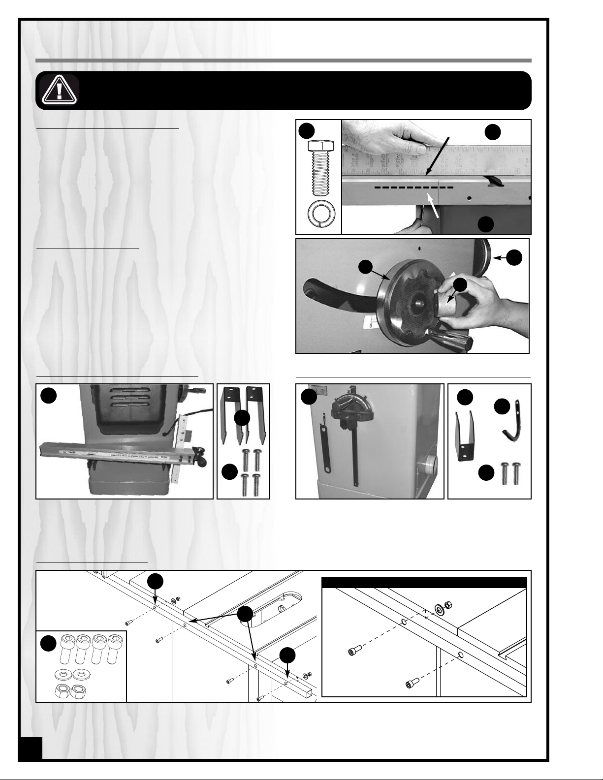
INSTALL THE TABLE EXTENSION WINGS
ttach the table extension wings to the main table
A
using 6 hex head bolts (3 per wing) and 6 lock washers A. Align the table extensions with the table and
oosely attach the bolts. Place a straightedge on the
l
table and extension as shown to align the extension
table B and then tighten down the bolts.
Note: Be sure that the table extension wings are flush with
front edge of table
C.
INSTALL THE HANDWHEELS
1. Install one handwheel onto the shaft at the front of the
saw as shown in A.
Note: The slots in the handwheel must be aligned with the
spring pin on the shaft.
2. Thread a lock knob B into the handwheel shaft to
secure the handwheel in place.
3. Repeat with the second handwheel, on the shaft located on the right side of the saw cabinet, C.
MOUNT THE RIP FENCE STORAGE BRACKETS
B
A
A
level here
flush here
B
C
C
A
B
MOUNT THEMITER GAUGE & ARBORWRENCH STORAGE BRACKETS
C
A
B
C
Install the fence storage brackets A (the two larger
ones) on the left side of the saw as shown in B, using 4
Phillips head screws C.
Install the miter gauge storage bracket A (the smaller
one) and arbor wrench storage bracket B on the right
side of the saw as shown in C, using 2 Phillips head
screws D per bracket.
D
INSTALL THE REAR FENCE RAIL
B
CLOSE UP
C
A
B
Attach the rear rail to the rear of the table using 4 cap screws, 2 flat washers and 2 hex nuts A (1 screw with washer
and nut and both extension wings, B, and 2 cap screws on the main table C. Tighten with the supplied 6 mm Allen
key.
10
 Loading...