


Cast iron frame & precision balanced aluminum wheels with replaceable rubber tires.
2 cutting speeds for excellent results in either hard or soft wood.
Precision blade guide bearing included.
Aluminum miter gauge with handle.
Large, stable cast iron table and slide out steel extension wing.
Includes goose neck style work light. (Bulb not included)
Smooth running, durable 1/2 HP motor.
Safety lock-out switch with removable key to prevent unauthorized use.
Built-in blade cleaning brush keeps tires free of dust and chips.
Telescoping extension table with retractable fence attachment.
WHEEL SIZE 12” (316 mm)
WHEEL SPEEDS (2) 483/825 RPM
BLADE SPEEDS (2)
1580/2710 FPM (480/820 MPM)
MAX BLADE WIDTH 1/2” (13 mm)
MIN BLADE WIDTH 1/8” (3.2 mm)
BLADE LENGTH 80” (2032 mm)
TABLE SIZE
13” x 13” (330 mm x 330 mm)
TABLE SIZE WITH EXTENSION 20” x 13” (508 mm x 330 mm)
TABLE TILT
0 – 45° right
TABLE HEIGHT
38 3/4 (985 mm)
MAX WIDTH OF CUT 12” (305 mm)
MAX DEPTH OF CUT 5” (125 mm)
DUST PORT
2 1/2” (63 mm)
BASE DIMENSIONS (L X W) 30” x 21” (710 mm x 540 mm)
MOTOR
1/2 HP, 110V, 7A
WEIGHT
154 LBS (70 KG)
REVISION 1 MARCH 14/07
© COPYRIGHT GENERAL INTERNATIONAL 03/2007

GENERAL® INTERNATIONAL
8360 Champ-d’Eau, Montreal (Quebec) Canada H1P 1Y3 Telephone (514) 326-1161 • Fax (514) 326-5555 • www.general.ca
THANK YOU for choosing this General International Star-Shop model 90-050 Bandsaw. This bandsaw has been carefully tested and inspected before shipment and if properly used and maintained, will provide you with years of reliable service. To ensure optimum performance and trouble-free operation, and to get the most from your investment, please take the time to read this manual before assembling, installing and operating the unit.
The manual’s purpose is to familiarize you with the safe operation, basic function, and features of this unit as well as the set-up, maintenance and identification of its parts and components. This manual is not intended as a substitute for formal woodworking instruction, nor to offer the user instruction in the craft of woodworking. If you are not sure about the safety of performing a certain operation or procedure, do not proceed until you can confirm, from knowledgeable and qualified sources, that it is safe to do so.
Once you’ve read through these instructions, keep this manual handy for future reference.
GENERAL ® INTERNATIONAL WARRANTY
All component parts of General® International Star-Shop machinery are carefully tested and inspected during all stages of production, and each machine is thoroughly inspected upon completion of assembly. Because of our commitment to quality and customer satisfaction, General® International agrees to repair or replace, within a period of 24 months from date of purchase, any genuine part or parts which, upon examination, prove to be defective in workmanship or material. In order to obtain this warranty, all defective parts must be returned freight pre-paid to General® International Mfg. Co., Ltd. Repairs attempted without our written authorization will void this warranty.
Disclaimer: The information and specifications in this manual pertain to the unit as it was supplied from the factory at the time of printing. Because we are committed to making constant improvements, General International reserves the right to make changes to components, parts or features of this unit as deemed necessary, without prior notice and without obligation to install any such changes on previously delivered units. Reasonable care is taken at the factory to ensure that the specifications and information in this manual corresponds with that of the unit with which it was supplied. However, special orders and “after factory”
modifications may render some or all information in this manual inapplicable to your machine. Further, as several generations of this model of bandsaw and several versions of this manual may be in circulation, if you own an earlier or later version of this unit, this manual may not depict your machine exactly. If you have any doubts or questions contact your retailer or our support line with the model and serial number of your unit for clarification.

Rules for Safe Operation
To help ensure safe operation, please take a moment to learn the machine’s applications and limitations, as well as potential hazards. GENERAL® INTERNATIONAL disclaims any real or implied warranty and holds itself harmless for any injury that may result from improper use of its equipment.
1.Learn the machine’s applications and limitations, as well as the specific potential hazards particular to this machine. Follow available safety instructions and safety rules carefully.
2.Keep working area clean and be sure adequate lighting is available.
3.Do not wear loose clothing, gloves, bracelets, necklaces, or jewellery while operating the bandsaw. Wear face, eye, ear, respiratory and body protection devices, as indicated for the operation or environment.
4.Keep hands well away from blades and all moving parts. Do not clear chips and sawdust away with hands. Use a brush.
5.Make sure all cutting tools are moving at operation speed before feeding.
6.Do not feed the material too quickly. The cutting tool will perform better and be safer working at the rate for which it was designed.
7.Whenever possible use a dust collector with shaving hood to minimize health hazards.
8.Never leave the machine with the power on.
9.Stop the feeder before stopping the cutting tool.
10.Keep children away. Make sure that visitors are kept at a safe distance from the work area.
11.Never stand on tool. Serious injury could occur if the tool is tipped or if the cutting tool is unintentionally contacted.
12.Adjust blade tension and tracking before starting to cut.
13.Use suitable support if stock does not have a flat surface.
14.Do not force the machine. It will do the job better and be safer at a rate for which it was designed.
15.Keep guards in place and in working order. If a guard must be removed for maintenance or cleaning make sure it is properly attached before using the tool again.
16.Be sure that key and adjusting wrenches have been removed before turning power on.
17.Use only accessories designed for the machine.
18.Do not work on long stock without adequate support on the out feed end of the table.
19.Make sure tool is properly grounded. If tool is equipped with three-prong plug, it should be plugged into a three-pole electrical receptacle. Never remove the third prong.
20.Always disconnect tool before servicing and when changing accessories such as blades, bits, cutters.
21.Make sure that switch is in "OFF" position before plugging in cord.
22.Adjust and position upper and lower blade guides before starting to cut. Upper blade guide should be adjusted to approximately 1/8” above the material to be cut.
23.Hold material firmly against the table.
24.Saw teeth must point down toward the table.
25.Use ONLY recommended accessories. Use of accessories NOT recommended by General International may result in a risk of injury.
26.Do not use this bandsaw for other than it’s intended use. If used for other purposes, General International disclaims any real or implied warranty and holds itself harmless for any injury, which may result from that use.

ELECTRICAL REQUIREMENTS
Before connecting the machine to the power source, verify that the voltage of your power supply corresponds with the voltage specified on the motor I.D. nameplate. A power source with greater voltage than needed can result in serious injury to the user as well as damage to the machine. If in doubt, contact a qualified electrician before connecting to the power source.
This tool is for indoor use only. Do not expose to rain or use in wet or damp locations.
Connect the motor plugs and then plug the bandsaw into a proper receptacle. Your power tools should be connected to a dedicated electrical circuit of not less than #12 wire and should be protected with a 15 amp time lag fuse.
GROUNDING: In the event of an electrical malfunction or short circuit, grounding reduces the risk of electric shock to. The motor of this machine is wired for 110V single phase operation and is equipped with a 3-conductor cord and a 3-prong grounded plug to fit a grounded type receptacle, . Do not remove the 3rd prong (grounding pin) to make it fit into an old 2-hole wall socket. If an adaptor plug is used,
  , it must be attached to the metal screw of the receptacle.
Note: The use of an adaptor plug is illegal in some areas. Check your local codes.
DO NOT MODIFY THE PLUG PROVIDED.
If it will not fit your receptacle, have the proper receptacle installed by a qualified electrician.
CHECK with a qualified electrician or service person if you do not completely understand these grounding instructions, or if you are not sure the tool is properly grounded.
EXTENSION CORDS:
USE ONLY 3-WIRE EXTENSION CORDS THAT HAVE 3-PRONG GROUNDING PLUGS AND 3-POLE RECEPTACLES THAT ACCEPT THE TOOLS’ PLUG. REPAIR OR REPLACE A DAMAGED OR WORN POWER CORD OR PLUG IMMEDIATELY.
If you find it necessary to use an extension cord with your machine make sure the cord rating is suitable for the amperage listed on the motor I.D. plate. An undersized cord will cause a drop in line voltage resulting in loss of power and overheating. The accompanying chart shows the correct size extension cord to be used based on cord length and motor I.D. plate amp rating. If in doubt, use the next heavier gauge. The smaller the gauge number, the heavier the cord.
AMPERES |
|
EXTENSION CORD LENGTH |
|
||
(AMPS) |
|
|
|
|
|
25 FEET |
50 FEET |
100 FEET |
150 FEET |
||
|
|||||
|
|
|
|
|
|
<6 |
18 |
16 |
16 |
14 |
|
6 TO 10 |
18 |
16 |
14 |
12 |
|
10 TO 12 |
16 |
16 |
14 |
12 |
|
12 TO 16 |
14 |
12 |
NA |
NA |
|
|
|
|
|
|
|
NA = Not Available
4

12” BANDSAW
90-050
IDENTIFICATION OF MAIN PARTS AND COMPONENTS
|
|
|
|
|
|
|
|
|
|
|
|
|
|
|
|
|
|
|
|
|
|
|
|
|
|
|
|
|
|
|
|
|
|
|
|
|
|
|
|
|
|
|
|
|
|
|
|
|
|
|
|
|
|
|
|
|
|
|
|
|
|
|
|
|
|
|
|
|
|
|
|
|
|
|
|
|
|
|
|
|
|
|
|
|
|
|
|
|
|
|
|
|
|
|
|
|
|
|
|
|
|
|
|
|
|
|
|
|
|
|
|
|
|
|
|
|
|
|
|
|
|
|
|
|
|
|
|
|
|
|
|
|
|
|
|
|
|
|
|
|
|
|
|
|
|
|
|
|
|
|
|
|
|
|
|
|
|
|
|
|
|
|
|
|
|
|
|
|
|
|
|
|
|
|
|
|
|
|
|
BLADE TENSION KNOB |
|
|
UPPER BLADE GUIDE LOCK KNOB |
||||||||||||||
WORK LIGHT |
|
|
TABLE TILT LOCK KNOB |
||||||||||||||
MITER GAUGE |
|
|
STAND |
||||||||||||||
TABLE ALIGNING PIN |
|
|
FOOT PAD |
||||||||||||||
DUST PORT |
|
|
TABLE INSERT |
||||||||||||||
BLADE |
|
|
UPPER WHEEL COVER DOOR |
||||||||||||||
ON/OFF SWITCH |
|
|
LOWER WHEEL COVER DOOR |
||||||||||||||
5
UNPACKING & SET UP
ADDITIONAL TOOLS NEEDED
• Philips screwdriver
• Adjustable wrench
• Straightedge
• Extra person for help with lifting
UNPACKING
Carefully unpack and remove the bandsaw and its components from the box and check for missing or damaged items as per the list of contents below.
Note: Please report any damaged or missing items to your General International distributor immediately.
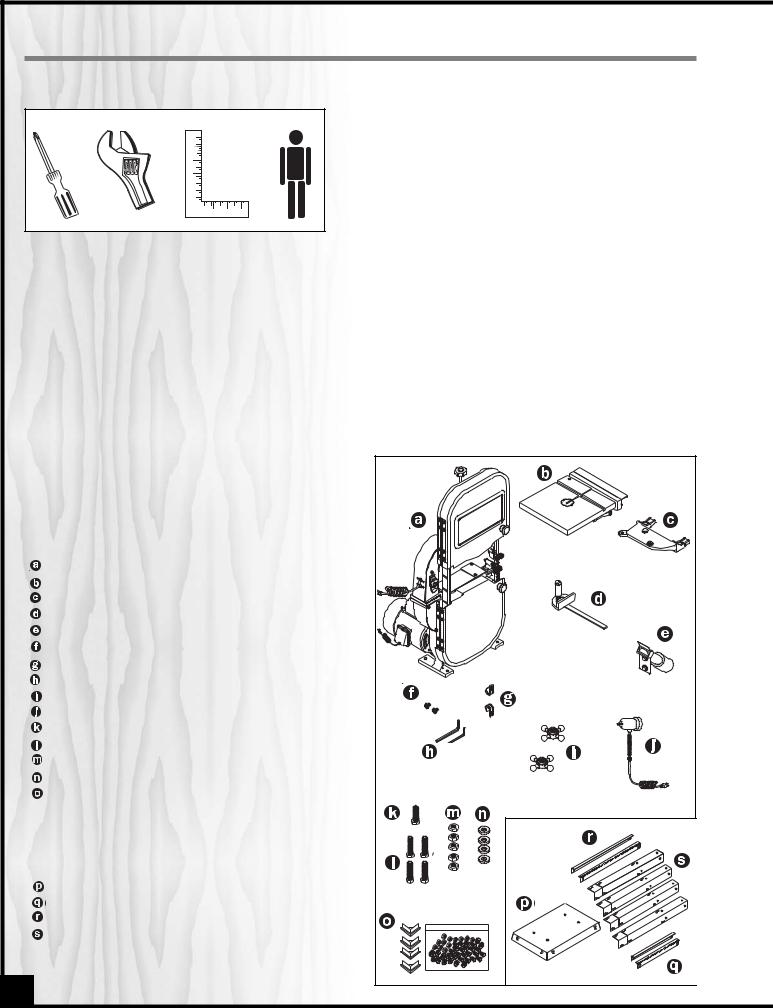
LIST OF CONTENTS |
|
||
Once the parts have been removed from the |
|||
packaging, you should have the following items: |
|||
|
|
|
Qty |
BANDSAW W/MOTOR . . . . . . . . . . . . . . . . . . . . . . . . .1 |
|||
TABLE W/EXTENSION WING . . . . . . . . . . . . . . . . . . . . .1 |
|||
TRUNNION SUPPORT BRACKET . . . . . . . . . . . . . . . . . .1 |
|||
MITER GAUGE |
|
. . . . . . . . . . . . . . . . . . . . . . . . . . . . . . .1 |
|
DUST PORT . . . . . . . . . . . . . . . . . . . . . . . . . . . . . . . . . .1 |
|||
SCREWS |
. . . . . . . . . . . . . . . . . . . . . . . . . . . . . . . .2 |
||
POWER CORD HOOKS |
. . . . . . . . . . . . . . . . . . . . . . . .2 |
||
ALLEN KEY |
. . . . . . . . . . . . . . . . . . . . . . . . . . . . . . . .2 |
||
TABLE TILT LOCK KNOBS |
. . . . . . . . . . . . . . . . . . . . . . .2 |
||
WORK LIGHT |
. . . . . . . . . . . . . . . . . . . . . . . . . . . . . . . .1 |
||
BOLT 5/16” X 1” |
. . . . . . . . . . . . . . . . . . . . . . . . . . . . . .1 |
||
BOLT 5/16” X 1 1/4” . . . . . . . . . . . . . . . . . . . . . . . . . . .4 |
|||
HEX NUT 5/16” |
. . . . . . . . . . . . . . . . . . . . . . . . . . . . . . .5 |
||
LARGE WASHER |
. . . . . . . . . . . . . . . . . . . . . . . . . . . . . .4 |
||
HARDWARE BAG . . . . . . . . . . . . . . . . . . . . . . . . . . . . .1 |
|||
CARRIAGE BOLT . . . . . . . . . . . . . . . . . .32 |
|||
HEX. NUT . . . . . . . . . . . . . . . . . . . . . . . .32 |
|||
WASHER . . . . . . . . . . . . . . . . . . . . . . . .32 |
|||
FOOT PAD |
. . . . . . . . . . . . . . . . . . . . . . .4 |
||
TOP PLATE |
. . . . . . . . . . . . . . . . . . . . . . . . . . . . . . . .1 |
||
SHORT LOWER BRACKET |
. . . . . . . . . . . . . . . . . . . . . . .2 |
||
LONG LOWER BRACKET |
. . . . . . . . . . . . . . . . . . . . . . .2 |
||
LEG |
. . . . . . . . . . . . . . . . . . . . . . . . . . . . . . . .4 |
||
6 |
|
|
|

ASSEMBLY
ASSEMBLING THE STAND
1.Lay the top plate  upside face.
2.Attach the 4 legs  to the
 using 4 carriage bolts,
Note: Do not tighten hex nuts are attached.
ATTACHING THE BANDSAW TO ST
The bandsaw is heavy. The tant will be needed to lift
1.Lift the saw body  with the help of an assistant and place it on the stand.
2. Using 4 long hex head bolts  , 8 flat washers , and 4 hex nuts , secure the bandsaw to
the stand and tighten all mounting bolts.
brackets  and 2 short brackets inside for the legs, using carriage bolts
nuts  .
.
foot pads  on the bottom of each
stand on a flat surface to square it up tighten all the nuts.
DUST PORT
The dust port has a 2-1/2” opening to accommodate connection to a dust collector (not included).
1.Remove the bolts and washers from the dust port.
2.Open the lower wheel cover door  .
.
3.Attach the dust port  to the edge of the door using the same hex head bolts and washers
  .
.
4.Tighten the bolts and close the door.
7

MOUNTING THE TRUNNION SUPPORT BRACKET |
INSTALLING 90° TABLE TILT STOP BOLT |
||
|
|
|
|
|
|
|
|
|
|
|
|
1. Remove the 2 hex head bolts and washers  , located on the lower band saw housing.
2.Place the trunnion support bracket  on the saw body, aligning the mounting holes.
3.Place the washers on the hex head bolts, and insert into the threaded holes, through the bracket and saw body. Tighten.
INSTALLING THE BANDSAW TABLE
1. Remove the table insert from the table.
2.The extension table must be removed before placing table onto saw. Unscrew the stop-
screw on the rear extension table guide bar and pull the extension table off of the main table.
4. Slip the 2 table tilt trunnion bolts through the holes in the trunnion brackets (front & rear) as shown.
1. Thread the nut onto the table stop bolt and screw bolt into the rear tab  on the trunnion support bracket. Tighten the nut down onto the bracket tab.
2.After installing the table, the 90° stop bolt can be adjusted up or down as needed to “stop” the table at 90° to the blade.
90° CW
3. Guide the table slot over the saw blade and rotate 90° clockwise so the slot is perpendicular to the blade.
5. Place a lock knob on each bolt and adjust the table, aligning the zero scale mark to the pointer , then tighten the knobs .
8
 Loading...