


SETUP & OPERATION MANUAL
FEATURES
 Designed for excellent results, for both wood and metal cutting applications.
 Select between metal & wood cutting speed ranges with a simple belt position change.
 Dynamically balanced cast-iron wheels.
 Solid, high quality, precision-machined, ribbed cast-iron table with 5° left and 45° right tilting action.
 New and improved! Now includes upgraded 90-075B deluxe Excalibur rip fence system.
 Quick release blade tension lever.
 Dual/opposing blade guide bearing system.
 2 built-in 4" diameter dust chutes for better dust collection.
 Quick easy adjust variable speed control and digital display for blade speed in FEET/MIN.
 Large paddle style stop switch with lockout safety pin and lock-out switch with key for main power.
 Miter gauge, laser line marker and worklight included.
SPECIFICATIONS
WHEEL SIZE 17” (430 MM)
WHEEL SPEED
WOOD: 122 - 810 RPM / METAL: 23 - 146 RPM
BLADE WIDTH
1⁄8” TO 1” (3 TO 25.4 MM)
BLADE LENGTH
131 1⁄2” (3340 MM)
TABLE SIZE
23 1⁄2” X 17” (600 X 430 MM)
TABLE TILT
0° TO 45° (RIGHT) / 0° TO 5° (LEFT)
TABLE HEIGHT
39 3⁄4” (1010 MM)
MAXIMUM DEPTH OF CUT 11 1⁄2” (295 MM)
MAXIMUM WIDTH OF CUT 16 1⁄4” (410 MM)
MAXIMUM CUTTING (RIP FENCE) 14 5⁄8” (370 MM)
DUST PORT (2)
4” (102 MM)
BLADE SPEED
WOOD 540 - 3600 FPM (165 - 1100 MPM) METAL 100 - 650 FPM (30 - 200 MPM)
BASE DIMENSIONS (L X W)
29 1⁄2” X 17 3⁄4” (749 X 451 MM)
MOTOR
2 HP, 220 V, 3 PH, 7 A)
INPUT POWER 220 V, 1 PH
WEIGHT
440 LBS (200 KG)
17” WOOD / METAL BANDSAW
MODEL
#90-320
VERSION 4_Revision 2 - August 16, 201
© Copyright General® International 08/2012

GENERAL® INTERNATIONAL
8360 Champ-d’Eau, Montreal (Quebec) Canada H1P 1Y3 Telephone (514) 326-1161 • Fax (514) 326-5555 • www.general.ca
THANK YOU for choosing this General® International model 90-320 - 17” Wood / Metal Bandsaw. This bandsaw has been carefully tested and inspected before shipment and if properly used and maintained, will provide you with years of reliable service. For your safety, as well as to ensure optimum performance and trouble-free operation, and to get the most from your investment, please take the time to read this manual before assembling, installing and operating the unit.
The manual’s purpose is to familiarize you with the safe operation, basic function, and features of this bandsaw as well as the set-up, maintenance and identification of its parts and components. This manual is not intended as a substitute for formal woodworking instruction, nor to offer the user instruction in the craft of woodworking. If you are not sure about the safety of performing a certain operation or procedure, do not proceed until you can confirm, from knowledgeable and qualified sources, that it is safe to do so.
Once you’ve read through these instructions, keep this manual handy for future reference.
Disclaimer: The information and specifications in this manual pertain to the unit as it was supplied from the factory at the time of printing. Because we are committed to making constant improvements, General® International reserves the right to make changes to components, parts or features of this unit as deemed necessary, without prior notice and without obligation to install any such changes on previously delivered units. Reasonable care is taken at the factory to ensure that the specifications and information in this manual corresponds with that of the unit with which it was supplied.
However, special orders and “after factory” modifications may render some or all information in this manual inapplicable to your machine. Further, as several generations of this model of bandsaw and several versions of this manual may be in circulation, if you own an earlier or later version of this unit, this manual may not depict your machine exactly. If you have any doubts or questions contact your retailer or our support line with the model and serial number of your unit for clarification.

GENERAL® & GENERAL® INTERNATIONAL WARRANTY
All component parts of General®, General® International and Excalibur by General International ® products are carefully inspected during all stages of production and each unit is thoroughly inspected upon completion of assembly.
Limited Lifetime Warranty
Because of our commitment to quality and customer satisfaction, General® and General® International agree to repair or replace any part or component which upon examination, proves to be defective in either workmanship or material to the original purchaser for the life of the tool. However, the Limited Lifetime Warranty does not cover any product used for professionnal or commercial production purposes nor for industrial or educational applications. Such cases are covered by our Standard 2-year Limited Warranty only. The Limited Lifetime Warranty is also subject to the “Conditions and Exceptions” as listed below.
Standard 2-Year Limited Warranty
All products not covered by our lifetime warranty including products used in commercial, industrial and educational applications are warranted for a period of 2 years (24 months) from the date of purchase. General® and General® International agree to repair or replace any part or component which upon examination, proves to be defective in either workmanship or material to the original purchaser during this 2-year warranty period, subject to the “conditions and exceptions” as listed below.
To file a Claim
To file a claim under our Standard 2-year Limited Warranty or under our Limited Lifetime Warranty, all defective parts, components or machinery must be returned freight or postage prepaid to General® International, or to a nearby distributor, repair center or other location designated by General® International. For further details call our service department at 1-888- 949-1161 or your local distributor for assistance when filing your claim.
Along with the return of the product being claimed for warranty, a copy of the original proof of purchase and a “letter of claim” must be included (a warranty claim form can also be used and can be obtained, upon request, from General® International or an authorized distributor) clearly stating the model and serial number of the unit (if applicable) and including an explanation of the complaint or presumed defect in material or workmanship.
CONDITIONS AND EXCEPTIONS:
This coverage is extended to the original purchaser only. Prior warranty registration is not required but documented proof of purchase i.e. a copy of original sales invoice or receipt showing the date and location of the purchase as well as the purchase price paid, must be provided at the time of claim.
Warranty does not include failures, breakage or defects deemed after inspection by General® or General® International to have been directly or indirectly caused by or resulting from; improper use, or lack of or improper maintenance, misuse or abuse, negligence, accidents, damage in handling or transport, or normal wear and tear of any generally considered consumable parts or components.
Repairs made without the written consent of General® Internationallwill void all warranty.

TABLE OF CONTENTS
Rules for safe operation . . . . . . . . . . . . . .5-6
Electrical requirements . . . . . . . . . . . . . . .7
Grounding instructions . . . . . . . . . . . . . . . . . . . . . . .7 Circuit capacity . . . . . . . . . . . . . . . . . . . . . . . . . . . . .7 Extension cords . . . . . . . . . . . . . . . . . . . . . . . . . . . . .7
Identification of main parts
and components . . . . . . . . . . . . . . . . . . . .8
Basic Functions . . . . . . . . . . . . . . . . . . . . .9
Lifting and handling the machine . . . . . . . .9
Unpacking . . . . . . . . . . . . . . . . . . . . . . . .10
List of contents . . . . . . . . . . . . . . . . . . . . . . . . . . . . .10 Additional requirements for set up . . . . . . . . . . . .10
Placement within the shop / |
|
Establishing a safety zone . . . . . . . . . . |
. . .11 |
Clean up . . . . . . . . . . . . . . . . . . . . . . |
. . .11 |
Assembly instructions . . . . . . . . . . . . . |
12-15 |
Install the table . . . . . . . . . . . . . . . . . . . . . . . . . . . . .12 Install and adjust the 90º table sstop bolt . . . . . .12 Install the blade guard height adjustment handwheel . . . . . . . . . . . . . . . . . . . . . . . . . . . . . . . .13 Installing the laser line marker . . . . . . . . . . . . . . . .14 Install the fence assembly . . . . . . . . . . . . . . . . . . .15
Basic adjustments & controls . . . . . . . .15-17
On/Off switch & safety pin . . . . . . . . . . . . . . . . . . .15 Lock-out power switch . . . . . . . . . . . . . . . . . . . . . .15 Connecting to a power source . . . . . . . . . . . . . . .16 Tilting the table . . . . . . . . . . . . . . . . . . . . . . . . . . . . .16 Adjusting the blade guard for depth of cut . . . .16 Worklight . . . . . . . . . . . . . . . . . . . . . . . . . . . . . . . . . .17
Recommended adjustments . . . . . . . . .17-24
Removing/Installing the blade . . . . . . . . . . . . . . .17 Blade clearance . . . . . . . . . . . . . . . . . . . . . . . . .17-18 Blade selection . . . . . . . . . . . . . . . . . . . . . . . . . . . .19 Adjusting blade tension . . . . . . . . . . . . . . . . . . . . .20 Blade tracking adjustments . . . . . . . . . . . . . . . . . .21 Adjusting the upper/lower blade guides and thrust bearings . . . . . . . . . . . . . . . . . . . . . . . . . .22-23
Blade speed control . . . . . . . . . . . . . . . . . . . . . . . .22 Changing blade speed range - switching from wood to metal cutting . . . . . . . . . . . . . . . . . . . . . .43
Operating instructions . . . . . . . . . . . . .25-26
Connecting to a dust collector . . . . . . . . . . . . . . .25 Checklist before starting . . . . . . . . . . . . . . . . . . . . .25 Operations step-by-step . . . . . . . . . . . . . . . . . . . . .25 Using the rip fence . . . . . . . . . . . . . . . . . . . . . . . . .26 Using the miter gauge . . . . . . . . . . . . . . . . . . . . . .26 Cutting curves . . . . . . . . . . . . . . . . . . . . . . . . . . . . .26 Cutting circles . . . . . . . . . . . . . . . . . . . . . . . . . . . . .26
Periodic Maintenance . . . . . . . . . . . . . . . .27
Required Maintenance . . . . . . . . . . . . .27-30
Lubrication . . . . . . . . . . . . . . . . . . . . . . . . . . . . . . . .27 Replacing the bandsaw blade . . . . . . . . . . . . . . .27 Replacing the upper and lower blade guides and thrust bearings . . . . . . . . . . . . . . . . . . . . . . . . .28 Replacing the wheel tire . . . . . . . . . . . . . . . . . . . .29 Adjusting/replacing the wheel/blade brushes . .29
Recommended optional accessories . . . . .30
Parts list & diagrams . . . . . . . . . . . . . .32-42
Wiring Diagram . . . . . . . . . . . . . . . . . . . .43

RULES FOR SAFE OPERATION
To help ensure safe operation, please take a moment to learn the machine’s applications and limitations, as well as potential hazards. General® International disclaims any real or implied warranty and holds itself harmless for any injury that may result from improper use of its equipment.
1.For your own safety read the instruction manual before operating this band saw.
2.This tool is for indoor use only. Do not expose to rain or use in wet or damp locations.
3.Do not operate this bandsaw when tired, distracted, or under the effects of drugs, alcohol or any medication that impairs reflexes or alertness.
4.The working area should be well lit, clean and free of debris.
5.Keep children and visitors at a safe distance when the bandsaw is in operation; do not permit them to operate the bandsaw.
6.Use right tool. Don't force tool or attachment to do a job for which it was not designed.
7.Childproof and tamper proof your shop and all machinery with locks, master electrical switches and switch keys, to prevent unauthorized or unsupervised use.
8.Stay alert! Give your work your undivided attention. Even a momentary distraction can lead to serious injury.
9.Fine particulate dust is a carcinogen that can be hazardous to health. Work in a well-ventilated area and whenever possible use a dust collector. Wear face, eye, ear, respiratory and body protection devices.
10.Always use safety glasses. Also use face protection or dust mask if cutting operation is dusty. Everyday eyeglasses only have impact resistant lenses, they are NOT safety glasses.
11.Do not wear loose clothing, gloves, bracelets, necklaces or other jewelry while the bandsaw is in operation. Wear protective hair covering to contain long hair and wear non-slip footwear.
12.Be sure that adjusting wrenches, tools, drinks and other clutter are removed from the machine and/or the table surface before operating.
13.Keep hands well away from blades and all moving parts. Use a brush, not hands, to clear away chips and dust.
14.Do not remove jammed cutoff pieces until blade has stopped.
15.Adjust and position upper and lower blade guides before starting to cut. Upper blade guide should be adjusted to approximately 1/8” above the material to be cut.
16.Adjust blade tension and tracking before starting to cut.
17.Saw teeth must point down toward the table.
18.Be sure that the blade has gained full operating speed before starting to cut.
19.Always use a clean, properly sharpened blade. Dirty or dull blades are unsafe and can lead to accidents.
20.Use suitable work piece support if the work piece does not have a flat surface.
21.Hold material firmly against the table.
19.Do not work on long stock without adequate support on the out feed end of the table.
20.If using a power feeder, stop the feeder before stopping the bandsaw.
21.Secure work. Use clamps or a vise to hold work when practical. It's safer than using your hand and it frees both hands to operate tool.
22.Do not push or force stock into the blade. The bandsaw will perform better and more safely when working at the rate for which it was designed.
23.Avoid working from awkward or off balance positions. Do not overreach and keep both feet on floor.
24.Keep guards in place and in working order. If a guard must be removed for maintenance or cleaning be sure it is properly re-attached before using the tool again.
25.Maintain proper adjustment of blade tension, blade guides, and thrust bearings.
26.Always disconnect the tool from the power source before servicing or changing accessories such as blades, or before performing any maintenance or cleaning, or if the machine will be left unattended.
5

RULES FOR SAFE OPERATION (CONT’D)
To help ensure safe operation, please take a moment to learn the machine’s applications and limitations, as well as potential hazards. General® International disclaims any real or implied warranty and holds itself harmless for any injury that may result from improper use of its equipment.
27.Make sure that the switch is in the “OFF” position before plugging in the power cord.
28Never leave the machine unattended while it is running or with the power on. Don't leave tool until it comes to a complete stop
29.Use of parts and accessories NOT recommended by GENERAL→ INTERNATIONAL may result in equipment malfunction or risk of injury.
30.Never stand on machinery. Serious injury could result if the tool is tipped over or if the cutting tool is unintentionally contacted.
31.Make sure the tool is properly grounded. If equipped with a 3-prong plug it should be used with a three-pole receptacle. Never remove the third prong.
32.Do not use this bandsaw for other than its intended use. If used for other purposes, GENERAL→ INTERNATIONAL disclaims any real implied warranty and holds itself harmless for any injury, which may result from that use.
33.Regularly inspect the machine for signs of damage or wear. Before further use of the tool, a guard or other part that is damaged should be carefully checked to determine that it will operate properly and perform its intended function - check for alignment of moving parts, binding of moving parts, breakage of parts, mounting, and any other conditions that may affect its operation.
34.Direction of feed. Feed work into a blade or cutter against the direction of rotation of the blade or cutter only.
35.The installer shall follow local regulations and National Electrical Code, ANSI/NFPA 70 installation requirements.
36.This tool should be connected to a grounded metal permanent wiring system; or to a system having an equipment-grounding conductor.
6
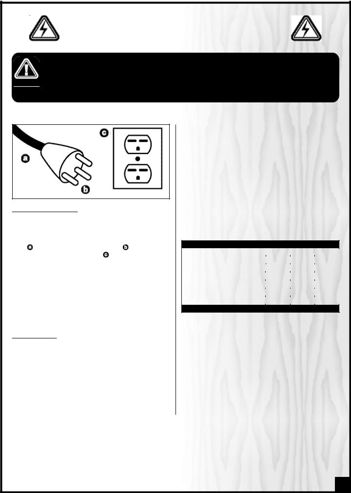
ELECTRICAL REQUIREMENTS
BEFORE CONNECTING THE MACHINE TO THE POWER SOURCE,VERIFY THAT THE VOLTAGE OF YOUR POWER SUPPLY CORRESPONDS WITH THE VOLTAGE SPECIFIED ON THE MOTOR I.D. NAMEPLATE. A POWER SOURCE WITH GREATER VOLTAGE THAN NEEDED CAN RESULT IN SERIOUS INJURY TO THE USER AS WELL AS DAMAGE TO THE MACHINE. IF IN DOUBT, CONTACT A QUALIFIED ELECTRICIAN BEFORE CONNECTING TO THE POWER SOURCE.
THIS TOOL IS FOR INDOOR USE ONLY. DO NOT EXPOSE TO RAIN OR USE IN WET OR DAMP LOCATIONS.
EXTENSION CORDS
The use of an extension cord is not generally recommended for 220V equipment. If you find it necessary, use only 3-wire extension cords that have 3-prong grounding plug and a matching 3-pole receptacle that accepts the tool’s plug. Repair or replace a damaged extension cord or plug immediately.
If you find it necessary to use an extension cord with your machine make sure the cord rating is suitable for the amperage listed on the motor I.D. plate. An undersized cord will cause a drop in line voltage resulting in loss of power and overheating. The accompanying chart shows the correct size extension cord to be used based on cord length and motor I.D. plate amp rating. If in doubt, use the next heavier gauge. The smaller the number, the heavier the gauge.
TABLE - MINIMUM GAUGE FOR CORD
AMPERE |
|
TOTAL LENGTH OF CORD IN FEET |
|
||
220 VOLTS |
50 FEET |
100 FEET |
200 FEET |
300 FEET |
|
RATING |
|
|
|
|
|
|
|
AWG |
|
|
|
|
|
|
|
|
|
< 5 |
-------> |
18 |
16 |
16 |
14 |
6 TO 10 |
-------> |
18 |
16 |
14 |
12 |
10 TO 12 |
-------> |
16 |
16 |
14 |
12 |
12 TO 16 |
-------> |
14 |
12 |
* NR |
* NR |
* NR = Not Recommended
7

17” WOOD / METAL BANDSAW |
||
90-320 |
|
|
IDENTIFICATION OF MAIN PARTS AND COMPONENTS |
||
FRONT VIEW |
REAR VIEW |
|
HOISTING EYEBOLT |
BLADE TENSION QUICK RELEASE LEVER |
|
LASER LINE MARKER |
BLADE GUARD LOCK KNOB |
|
BLADE TENSION WINDOW |
BLADE TRACKING ADJUSTMENT LEVER |
|
DIGITAL SPEED DISPLAY |
BLADE TRACKING ADJUSTMENT KNOB |
|
VARIABLE SPEED CONTROL KNOB |
BLADE TENSION ADJUSTMENT HAND WHEEL |
|
ON/OFF SWITCH WITH SAFETY KEY |
TABLE TILT ADJUSTMENT LOCK LEVER |
|
RIP FENCE SYSTEM |
TABLE TILT ADJUSTMENT KNOB |
|
MITER GAUGE |
DUST CHUTE |
|
BLADE GUARD |
LOWER WHEEL TILT ADJUSTMENT SCREWS |
|
WORKLIGHT |
BELT TENSION ADJUSTMENT HAND WHEEL |
|
BLADE GUARD HEIGHT ADJUSTMENT HAND |
BELT TENSION ADJUSTMENT MECHANISM |
|
WHEEL |
MOTOR |
|
BLADE TRACKING WINDOW |
||
|
||
8 |
|
|
BASIC FUNCTIONS
This model 90-320 electronic variable speed 17” bandsaw is designed to allow the user to adjust the speed of the blade to suit different wood or metal cutting needs. This unit includes all of the basic functions and features found on similar size bandsaws.
Featuring a front mounted digital blade speed display (in feet per minute) the unit is equipped with two speed ranges. By simply changing the positioning of the drive belt from one set of pulleys to the other the user can select a speed range, Metal (100-650 FPM) or Wood (540-3600 FPM), depending on the cutting application. The speed control adjustment knob allows the user to dial in the required speed within each speed range.
The 90-320 is designed to accommodate both wood and metal cutting blades from 1/8” – 1” in width and is supplied with one 1/2” general purpose wood cutting blade (factory installed) and one 1/2” general purpose metal cutting blade. Ideal blade length for the model 90-320 is 131 1/2” (3340mm).
Note: Generally speaking, because the upper wheel height is somewhat adjustable (to allow for blade tensioning), a blade length variation of plus or minus 1/2” from the “ideal blade length” can be accommodated.
Maximum inboard width of cut (space between the blade and the body of the saw) is 16 1/4”.
For cutting thicker stock or resawing, the maximum depth of cut (or max. workpiece height) is 11 1/2”.
An adjustable rip fence is supplied to serve as a straightedge to guide the workpiece for longer rip cuts. The fence can easily be removed and set aside when not required, for example when making curved cuts.
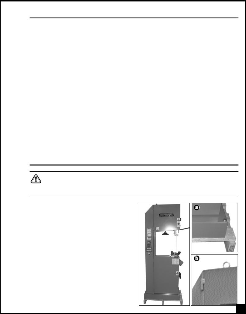
LIFTING AND HANDLING THE MACHINE
This model 90-320 17” Wood/Metal Bandsaw is very heavy. Do not over-exert. A hoist or forklift with chains will be needed for the following step.
To limit the risk of serious injury or damage to the machine, any equipment used to lift or move this machine (hoist or forklift) should have a rated capacity in excess 440lbs (200kg)
To limit the potential for damage in transport, this bandsaw is shipped from the factory bolted to its crate in the vertical position. With a forklift or hydraulic pallet jack, move the entire crate as close to the final installation location as possible, and then uncrate the saw and remove the screws that secure it to the crate  .
.
A hoisting eyebolt  is factory installed on the top of the saw frame to facilitate lifting and setting the saw down. Make sure to use an appropriate capacity hoist or forklift with chains properly secured to the hoisting eyebolt and lift the saw from the crate and carefully set it down in the desired location.
9
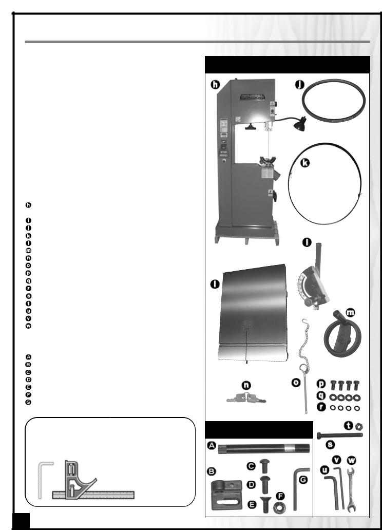
Carefully unpack and remove the unit and its components from its shipping container and check for missing or damaged items as per the list of contents below.
NOTE: Please report any damaged or missing items to your GENERAL® INTERNATIONAL distributor immediately.
LIST OF CONTENTS |
QTY |
|
|
|
|
BOX 1 - EXCALIBUR RIP FENCE
Note: Deluxe Excalibur Universal rip fence system is packed separately. Refer to the manual supplied in the box with Excalibur rip fence for complete list of contents.
SAW, TABLE & OTHER COMPONENTS*
The other components are stored inside the lower cabinet to prevent damage in shipping.
17” WOOD / METAL CUTTING BANDSAW . . . . . . . . . |
1 |
( WITH 1/2” X 6 TPI WOOD CUTTING BLADE INSTALLED ON)
BANDSAW TABLE . . . . . . . . . . . . . . . . . . . . . . . . . . . . .1 V-BELT (A-27) . . . . . . . . . . . . . . . . . . . . . . . . . . . . . . . .1 1/2” X 10 TPI METAL CUTTING BLADE . . . . . . . . . . . . .1 MITER GAUGE . . . . . . . . . . . . . . . . . . . . . . . . . . . . . . .1 BLADE GUARD HEIGHT ADJUSTMENT HAND WHEEL .1 LOCK-OUT SWICH KEY . . . . . . . . . . . . . . . . . . . . . . . . .2 SAFETY LOCKING PIN . . . . . . . . . . . . . . . . . . . . . . . . .1 HEX HEAD BOLT . . . . . . . . . . . . . . . . . . . . . . . . . . . . . .4 FLAT WASHER . . . . . . . . . . . . . . . . . . . . . . . . . . . . . . . .4 LOCK WASHER . . . . . . . . . . . . . . . . . . . . . . . . . . . . . . .4 TABLE STOP BOLT . . . . . . . . . . . . . . . . . . . . . . . . . . . . .1 STOP BOLT JAM NUT . . . . . . . . . . . . . . . . . . . . . . . . . .1 8 MM ALLEN KEY . . . . . . . . . . . . . . . . . . . . . . . . . . . . .1 5 MM ALLEN KEY . . . . . . . . . . . . . . . . . . . . . . . . . . . . .1 10 - 13 MM OPEN END WRENCH . . . . . . . . . . . . . . . .1
BOX 2 - LASER LINE MARKER (INSIDE LOWER CABINET)
LASER LINE MARKER . . . . . . . . . . . . . . . . . . . . . . . . . .1 MOUNTING BRACKET . . . . . . . . . . . . . . . . . . . . . . . . .1 BUTTON HEAD BOLT (SHORT) . . . . . . . . . . . . . . . . . . .1 BUTTON HEAD BOLT (LONG) . . . . . . . . . . . . . . . . . . . .1 SOCKET SCREW . . . . . . . . . . . . . . . . . . . . . . . . . . . . . .1 FLANGED NUT . . . . . . . . . . . . . . . . . . . . . . . . . . . . . . .1 3 MM ALLEN KEY . . . . . . . . . . . . . . . . . . . . . . . . . . . . .1
ADDITIONAL REQUIREMENTS FOR SET UP
•6 mm allen key
•Combination square
SAW, TABLE & OTHER COMPONENTS*
LASER LINE MARKER
10
PLACEMENT WITHIN THE SHOP / ESTABLISHING A SAFETY ZONE
PLACEMENT WITHIN THE SHOP
This machine should be installed and operated only on a solid, flat and stable floor that
the weight of the bandsaw 440 lbs operator. Using the dimensions shown plan for placement within your shop
operator to work unencumbered and unobstructed by foot traffic (either passing shop visitors or other shop workers) or other tools or machinery.
ESTABLISHING A SAFETY ZONE
For shops with frequent visitors or multiple operators, it is advisable to establish a Safety Zone around shop machi-nery. A clearly defined “no-go” zone on the floor around each machine can help avoid accidents that could cause injury to either the operator or the shop visitor. It is advi-sable to take a few moments to either paint (using non-slip paint) or using tape, define on the floor the limits or perimeter of each machines safety zone. Take steps to ensure that all operators and shop visitors are aware that these areas are off limits whenever a machine is running for everyone but the individual operating the unit.
95” |
32” |
41” |
CLEAN UP
The protective coating on the saw table prevents rust from forming during shipping and storage. Remove it by rubbing with a rag dipped in kerosene, mineral spirits or paint thinner. (Dispose of potentially flammable solvent-soaked rags according to manufacturer’s safety recommendations.)
A putty knife, held flat to avoid scratching the surface, may also be used to scrape off the coating followed by clean-up with solvent. Avoid rubbing the saw’s painted surfaces, as many solvent-based products will remo-ve paint.
To prevent rust, apply a light coating of paste wax or use regular applications of any after-market surface protectant or rust inhibitor.
Tip: With a screw driver, push a solvent-saturated rag into the T-slot to remove the grease.
11

ASSEMBLY INSTRUCTIONS
For your convenience this bandsaw is shipped from the factory partially assembled and requires only minimal assembly and set up before being put into service.
Serious personal injury could occur if you connect the machine to the power source before you have completed the installation and assembly steps. DO NOT connect the machine to the power source until instructed to do so.
INSTALL THE TABLE
1.To limit the risk of damage to the saw blade or frame, remove the blade. Follow the instructions in section “Blade Clearance” on page 17, then remove the blade as instructed in section “Removing/Installing the blade” on page 18.
This bandsaw table is heavy. Do not over-exert. The help of an assistant will be needed for the following step.
TABLE UNDERSIDE VIEW
|
|
|
|
|
|
|
|
|
|
|
|
|
|
|
|
|
|
|
|
2. |
Gently lower the table onto the table tilt trunnion |
3. Using the supplied 10 - 13 open end wrench, secure |
||
|
, with the table slots oriented as shown . |
the table to the trunnions with the 4 hex head bolts, |
||
|
|
|
lock washers and flat washers , in the assembly |
|
|
|
|
order shown in . |
|
4. |
Re-install the blade as instructed on page 19. |
|
|
|
INSTALL AND ADJUST THE 90º TABLE STOP BOLT
1.Loosen the locking lever  then turn the adjustment knob
  to tilt the table upwards as shown.
2.Thread the jam nut on the stop bolt  then thread
the bolt in the theaded hole located on the saw cabinet  , 7 or 8 turns.
12
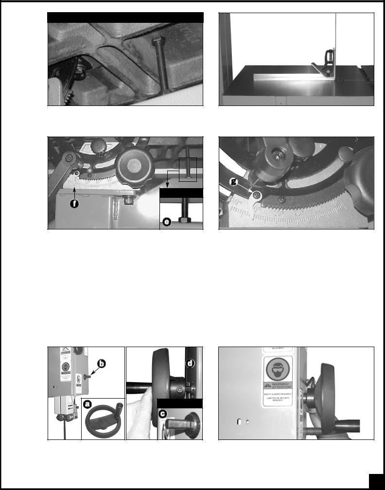
TABLE UNDERSIDE VIEW
3.Lower the table until it sits on top of the bolt.
CLOSE UP
4.Place a combination square flat on the table with the heel of the square flat against the saw blade.
3.Level the table until it is exactly 90° to the saw
blade then tighten the jam nut against the saw cabinet  .
.
Note: With the table set to 90º and the stop bolt at the correct height, make sure the table tilt angle indicator pointer  is set to read 0º.
4.If the pointer needs to be adjusted, loosen the screw  on the pointer of the front trunnion and adjust the pointer to the 0 point on the scale. Then re-tighten the screw to secure the pointer in place.
You will now be able to accurately return the table to the 90º position automatically without further adjustments and scale reading for any angle other than 0° will also be accurate.
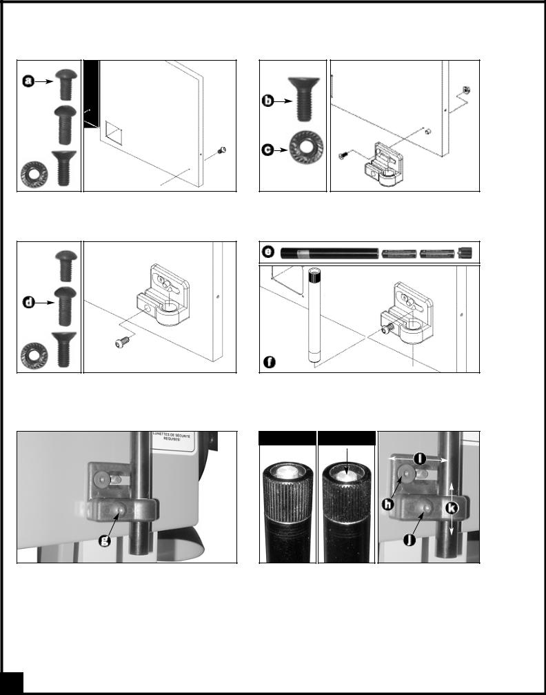
INSTALL THE BLADE GUARD HEIGHT ADJUSTMENT HANDWHEEL
CLOSE UP
1.Install the handwheel  on the shaft
 , located on
the right side of the upper wheel cover, by aligning the flat surface of the shaft  with the Allen bolt already mounted on the handwheel
  .
.
2.Tighten with the supplied 5 mm Allen key to secure the handwheel on the shaft.
13
INSTALL THE LASER LINE MARKER
The laser line marker will allow you to easily mark a straight cut line on your workpiece.
1.Thread the shorter button head bolt  from the inside of the upper cabinet.
3.Loosely screw the longer button head bolt  .
.
5.Using the supplied 3 mm Allen key, tighten the longer button head screw  , to secure the laser line marker into it’s mounting bracket.
2.Attach the mounting bracket to the front of the saw using the socket screw  through the door and the flange nut
  on the inside of the door.
4.Unscrew and remove the cap and install two AAA batteries  (not included), then fit the laser line
marker into the the hole in the mounting bracket  .
.
OFF ON
Align the laser beam on the blade as follows:
1.Press on the ON/OFF switch button (located on top of the laser line marker) to turn the laser ON.
2.Loosen the socket screw  and move the laser left
or right along the elongated hole  and/or loosen the button head bolt
  and move the laser up or down
  until the beam is aligned with the blade .
3.Press on the ON/OFF switch button once again to to turn the laser OFF.
14
 Loading...