


INSTALLATION GUIDE
Horizontal series
HRV MODEL 8160 and MODEL 8220 ERV MODEL 3160 and MODEL 3220

INSTALLATION GUIDE
eace of Mind
All GeneralAire products are backed by the best limited warranty in the industry, for
your peace of mind.
You benefit from a lifetime warranty on the core, a 10-year warranty (5 years + 5 years prorated) on our ventilation motors, a 5-year warranty on the enthalpic core, and a 5-year warranty on all other components. So you can breathe easy.
About Us
GeneralAire offers you a complete range of products designed to improve indoor air quality, and that provides a wide selection of accessories to facilitate installation.
Our vision – To offer a complete range of GeneralAire products that satisfy environmental concerns.
Whether your needs involve ventilation, purification, humidification or filtration, GeneralAire has the customized solution for you, with its range of quality products backed by the best warranty in the industry.
Installation
INFORMATION FOR INSTALLERS |
PAGE |
|
1. |
Ventilation needs |
3 |
2. |
Types of installation |
3 |
3. |
GeneralAire HRV/ERV systems |
6 |
4. |
Finding a suitable installation area for the HRV or ERV |
6 |
5. |
Installation of the HRV/ERV |
7 |
6. |
Rigid duct |
7 |
7. |
Insulated flex from unit to outside wall |
8 |
8. |
Condensation drain line |
9 |
9. |
Devoted electric receptacle |
10 |
10. |
Outside fresh air and exhaust air hoods |
11 |
11. |
Fresh air and exhaust air grilles |
12 |
12. |
Benefits of the DuotrolTM system |
13 |
13. |
Balancing the unit |
14 |
Functions and Controls
INFORMATION FOR HOME OWNERS AND INSTALLERS |
PAGE |
14. Controls and wiring |
15 |
Technical Information
INFORMATION FOR HOME OWNERS AND INSTALLERS |
PAGE |
|
15. Troubleshooting |
19 |
|
16. |
Wiring diagram |
20 |
17. |
Maintenance |
21 |
18. |
Specification and technical information |
22 |
2
Determine your ventilation needs
installation
How much fresh air do I need? Good air quality is based in part on the capacity of the home’s ventilation system.
Usually, the HRV’s or ERVs capacity is measured in CFM (cubic feet per minute) or L/s (Liters per seconds) of fresh air being distributed in the living space. The room count calculation or the air change per hour method shows you how to determine your ventilation needs.
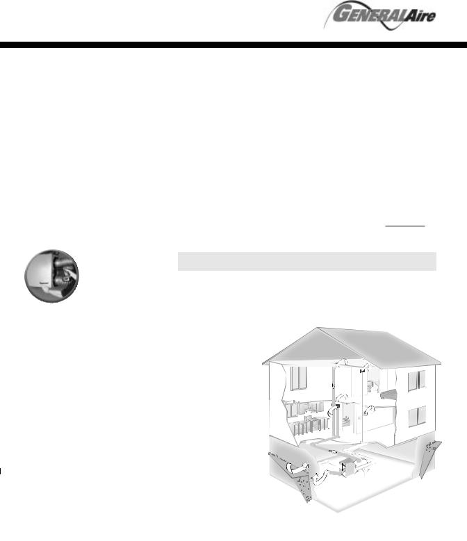
Independent system
installation
This application uses a devoted duct system for the
supply and the exhausting of stale air accumulated in the home.
It is recommended to install fresh air grilles in all
bedrooms and living areas. Exhaust the stale air from the bathroom, kitchen and laundry room.
1.Ventilation Needs
A. Room count calculation
|
LIVING SPACE |
Number of Rooms |
CFM (L/s) |
CFM Required |
|||||
|
Master Bedroom |
|
|
|
x 20 cfm (10 L/s)= |
|
|
|
|
|
With Basement |
|
|
|
x 20 cfm (10 L/s)= |
|
|
|
|
|
Without Basement |
|
|
|
|
|
|
|
|
|
Single Bedroom |
|
|
|
x 10 cfm (5 L/s)= |
|
|
|
|
|
Living Room |
|
|
|
x 10 cfm (5 L/s)= |
|
|
|
|
|
Dinning Room |
|
|
|
x 10 cfm (5 L/s)= |
|
|
|
|
|
Family Room |
|
|
|
x 10 cfm (5 L/s)= |
|
|
|
|
|
Recreation Room |
|
|
|
x 10 cfm (5 L/s)= |
|
|
|
|
|
Other |
|
|
|
|
|
|
|
|
|
|
|
|
|
|
|
|
|
|
|
Kitchen |
|
|
|
x 10 cfm (5 L/s)= |
|
|
|
|
|
Bathroom |
|
|
|
x 10 cfm (5 L/s)= |
|
|
|
|
|
Laundry Room |
|
|
|
x 10 cfm (5 L/s)= |
|
|
|
|
|
Utility Room |
|
|
|
x 10 cfm (5 L/s)= |
|
|
|
|
|
|
|
|
|
|
|
|
|
|
TOTAL ventilation requirement (add last column)=
1 CFM = 0.47189 L/s
1 L/s = 3.6 m3/hr
B. Air change per hour method
TOTAL cu ft x 0.35 per hr = total
Take total and divide by 60 to get CFM
Example: 25' x 40' house with basement
1,000 sq. ft. x 8' high x 2 (1st floor + basement) = 16,000 cu. ft. 16,000 cu. ft. x 0.35 ACH = 5,600 cu. ft.
5,600 cu. ft./60 minutes = 93 CFM
93 CFM is your ventilation need
2. Types of Installation
Independent System

INSTALLATION GUIDE
Exhaust at the source and supply in the return
installation
This application uses a devoted duct system for the
exhausting of stale air accumulated in the home. The fresh air is dumped into the return air duct and is distributed thru the home by the existing supply air ductwork of the forced air system.
Make sure when using this application that your fresh air duct connection to the forced air system return air duct is at least 3' from the forced air system. You should check with your local code or the forced air system’s manufacturer.
2. Types of Installation (continued)
There are different practices used to combine HRV or ERV to a forced air system.
Exhaust at the source
3'
To living space
From Bathroom or Kitchen
6'
18"
HRV/ERV
Forced Air System
* For minimum distance between return and forced air system, check with your local building codes and forced air system manufacturer.
Indirect Connection - Breathing Tee
Indirect Connection - Return Air Grille
A Breathing Tee is a ventilation air supply duct with an open tee located before the connection to the return air duct. It allows the HRV to function without supply air flow rates being affected by the forced air system’s fan speed.
Leaving a gap in the ventilation air supply duct in place of the breather tee is acceptable but not recommended.
With the return air grille approach, HRV or ERV ventilation supply air is “dumped” near a grille (between 4" and 12") in the return air duct upstream of the recirculation fan.
4" to 12" maximum
*See your local code before making an installation.
4

Exhaust and
supply in the return
installation
When using this application make sure that there is at least 6' between the fresh air and exhaust air connections of the
HRV or ERV in the return air duct.
Supply air from HRV or ERV must be at least 3' from the forced air system. Can be different from a region to an other.
You should check with your local code or the forced air system’s manufacturer.
Note
to installer
Fresh air must always be down-stream from the exhaust air in the return air duct of the forced air system.
Exhaust from the return and supply in supply
installation
When using this application make sure that the Supply air from HRV or ERV is at least 3' from the forced air system. Can be different from a region to an other. You should check with your local code or the forced air system’s manufacturer.
2. Types of installation (continued)
Exhaust and supply in the return
3’
6’
6’ |
To living space |
18”
HRV / ERV
Forced Air System
Simplified Connection |
FOR MINIMUM DISTANCE BETWEEN |
|
RETURN AND FORCED AIR SYSTEM |
|
Check with your local building codes and force air system manufacturer. |
Exhaust from return and supply in supply
6’
18”
HRV / ERV
Forced Air System
5

INSTALLATION
GUIDE
3. GeneralAire HRV/ERV systems
Installation Kit
Included in the installation kit:
•4 Collars
•2 Flexible Vinyl Ducts
•1 Condensation Drain Line
•1 Drain Adapter with Nut
•4 Tie Wraps (30”)
•16 screws (#10 x 5/8")
•4 screws (#10 x 1")
•4 Washers
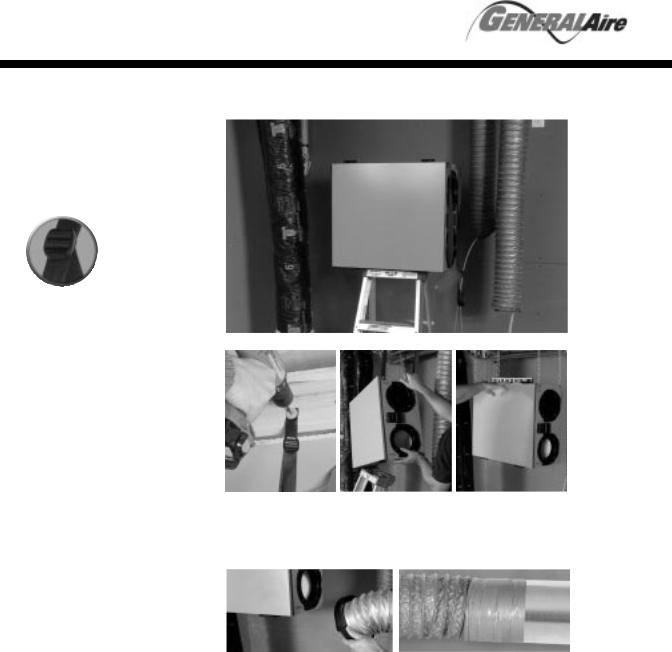
TIPS
to installer
Removing the core unit will facilitate your job.
Figure 3.1 Pull out the inserts first then use the straps to lift the unit out of the box.
Figure 3.2 Installation kit is shipped inside the unit. |
Figure 3.3 Installation kit. |
4. Finding a suitable installation area for HRV or ERV
The HRV or ERV units should be installed in a mechanical room or as close to an outside wall as possible. This would assure a short run of insulated flexible duct.
The HRV or ERV unit must always be installed in an area where the air is tempered to avoid freezing of the condensate line. The contractor should install the unit in area that is very accessible to allow the homeowner easy access for maintenance.
It is very important to install an electric receptacle (115v) near the HRV or ERV, a separate circuit breaker is also recommended. You should have access to a condensate drain near the HRV or ERV to avoid the use of condensate pump.
6
The SPMTM system is supplied with the HRV or ERV to allow one person mounting of unit.
SPMTM
attachment system
The entire line of GeneralAire HRV/ERV products is designed for installation by a single
person. “Single Person MountingTM” will enable you
to save time and effort by offering you a variable attachment system and maximizing your basement space.
TIPS
to installer
If unit is not level, improper drainage will occur and could lead to moisture and leakage problems.
TIPS
to installer
It is recommended to use approximately 16" of flexible duct (supplied in kit) between the HRV or ERV and your rigid duct (see figure 6.1). The flex duct is mounted the same way to the HRV or ERV as the insulated flex close on step 6 (see figure 6.2).
5. Installation of the HRV/ERV
figure 5.1 Place HRV/ERV on a stepladder.
figure 5.2 Attach your four straps to the |
figure 5.3 Pull on the middle strap and |
floor joist making sure that you attach |
gently push upward on the unit. Then |
thru the washers and the grommets. |
repeat procedure on other side. |
figure 5.4 When completing the procedure make sure that the HRV or ERV is leveled.
6. Rigid duct
figure 6.1 Mount flex to HRV/ERV. |
figure 6.2 Mount flex to rigid duct. |
7
 Loading...