


SETUP & OPERATION MANUAL
FEATURES
Heavy-duty enclosed stand for greater stability.
Sanding belt operates at any angle from horizontal to vertical.
Accurate belt tension and tracking adjustment.
Cast-iron table can be adjusted up or down for full belt use.
Safety switch with key. Unit cannot be started when key is removed from the switch.
Cast-iron miter gauge can be locked in position for quick and easy setup.
Adjustable, removable front table fence.
Graphite backing reduces friction for longer belt life.
SPECIFICATIONS
•Belt size
6” x 89” (152 x 2260 mm)
•Belt speed
3900 lin. fpm (1279 lin. mpm)
•Front table size (l x w)
97/8” x 29 5/8” (250 x 751 mm)
•Auxiliary table size (l x w)
97/8” x 11 7/8” (250 x 300 mm)
•Dust outlet 4” (102 mm)
•Base dimensions (l x w)
211/2” x 16 1/2’’ (546 x 420 mm)
•Overall dimensions (l x w x h)
50” x 21’’ x 49” (1270 x 533 x 1245 mm)
•Motor (pre-wired 220 V)
11/2 HP, 110/220 V, 18/9 A
•Weight
266lbs (121 kg)
Version #1_Revision #1 - August 2015
© Copyright General International
6” X 89” EDGE BELT SANDER
MODEL
#15-005

GENERAL® INTERNATIONAL
8360 Champ-d’Eau, Montreal (Quebec) Canada H1P 1Y3 Telephone (514) 326-1161 • Fax (514) 326-5555 • www.general.ca
THANK YOU for choosing this General® International model 15-005 6” X 89” edge belt sander. This sander has been carefully tested and inspected before shipment and if properly used and maintained, will provide you with years of reliable service. For your safety, as well as to ensure optimum performance and trouble-free operation, and to get the most from your investment, please take the time to read this manual before assembling, installing and operating the unit.
The manual’s purpose is to familiarize you with the safe operation, basic function, and features of this sander as well as the set-up, maintenance and identification of its parts and components. This manual is not intended as a substitute for formal woodworking instruction, nor to offer the user instruction in the craft of woodworking. If you are not sure about the safety of performing a certain operation or procedure, do not proceed until you can confirm, from knowledgeable and qualified sources, that it is safe to do so.
Once you’ve read through these instructions, keep this manual handy for future reference.
DISCLAIMER: The information and specifications in this manual pertain to the unit as it was supplied from the factory at the time of printing. Because we are committed to making constant improvements, General® International reserves the right to make changes to components, parts or features of this unit as deemed necessary, without prior notice and without obligation to install any such changes on previously delivered units. Reasonable care is taken at the factory to ensure that the specifications and information in this manual corresponds with that of the
unit with which it was supplied. However, special orders and “after factory” modifications may render some or all information in this manual inapplicable to your machine. Further, as several generations of this model of sander and several versions of this manual may be in circulation, if you own an earlier or later version of this unit, this manual may not depict your unit exactly. If you have any doubts or questions contact your retailer or our support line with the model and serial number of your unit for clarification.

GENERAL® INTERNATIONAL WARRANTY
All component parts of General® International and Excalibur by General International® products are carefully inspected during all stages of production and each unit is thoroughly inspected upon completion of assembly.
Limited Lifetime Warranty
Because of our commitment to quality and customer satisfaction, General® International agrees to repair or replace any part or component which upon examination, proves to be defective in either workmanship or material to the original purchaser for the life of the tool. However, the Limited Lifetime Warranty does not cover any product used for professional or commercial production purposes nor for industrial or educational applications. Such cases are covered by our Standard 2-year Limited Warranty only. The Limited Lifetime Warranty is also subject to the “Conditions and Exceptions” as listed below.
Standard 2-Year Limited Warranty
All products not covered by our lifetime warranty including products used in commercial, industrial and educational applications are warranted for a period of 2 years (24 months) from the date of purchase. General® International agrees to repair or replace any part or component which upon examination, proves to be defective in either workmanship or material to the original purchaser during this 2-year warranty period, subject to the “conditions and exceptions” as listed below.
To file a Claim
To file a claim under our Standard 2-year Limited Warranty or under our Limited Lifetime Warranty, all defective parts, components or machinery must be returned freight or postage prepaid to General® International, or to a nearby distributor, repair center or other location designated by General® International. For further details call our service department at 1-888-949-1161 or your local distributor for assistance when filing your claim.
Along with the return of the product being claimed for warranty, a copy of the original proof of purchase and a“letter of claim”must be included (a warranty claim form can also be used and can be obtained, upon request, from General® International or an authorized distributor) clearly stating the model and serial number of the unit (if applicable) and including an explanation of the complaint or presumed defect in material or workmanship.
CONDITIONS AND EXCEPTIONS:
This coverage is extended to the original purchaser only. Prior warranty registration is not required but documented proof of purchase i.e. a copy of original sales invoice or receipt showing the date and location of the purchase as well as the purchase price paid, must be provided at the time of claim.
Warranty does not include failures, breakage or defects deemed after inspection by General® International to have been directly or indirectly caused by or resulting from; improper use, or lack of or improper maintenance, misuse or abuse, negligence, accidents, damage in handling or transport, or normal wear and tear of any generally considered consumable parts or components.
Repairs made without the written consent of General® International will void all warranty.

TABLE OF CONTENTS
Rules for safe operation..................................................................................................... |
5 |
Electrical requirements....................................................................................................... |
6 |
Identification of main parts and components................................................................... |
7 |
Unpacking.......................................................................................................................... |
8 |
Basic functions................................................................................................................... |
8 |
Cleaning............................................................................................................................. |
9 |
Placement within the shop................................................................................................. |
9 |
Assembly instructions....................................................................................................... |
10 |
Assembling the stand.................................................................................................................................. |
10-12 |
Installing the machine on the stand............................................................................................................... |
12 |
Installing a sanding belt.............................................................................................................................. |
13-14 |
Installing the workpiece stop........................................................................................................................... |
15 |
Installing the auxiliary table........................................................................................................................ |
15-16 |
Connecting the switch...................................................................................................................................... |
16 |
Connecting to a dust collector....................................................................................................................... |
17 |
Basic adjustments and controls.................................................................................. |
17-21 |
Connecting to a power source....................................................................................................................... |
17 |
On/Off power switch......................................................................................................................................... |
17 |
Adjusting the height of the main table........................................................................................................... |
18 |
Adjusting the angle of the sanding head...................................................................................................... |
19 |
Installing and adjusting the miter gauge....................................................................................................... |
19 |
Selecting a sanding belt.................................................................................................................................. |
20 |
Belt tracking adjustment.............................................................................................................................. |
20-21 |
Operating instructions................................................................................................. |
21-22 |
Checklist before starting................................................................................................................................... |
21 |
Using the table fence........................................................................................................................................ |
22 |
Using the workpiece stop................................................................................................................................. |
22 |
Using the auxiliary table................................................................................................................................... |
22 |
Maintenance............................................................................................................... |
22-23 |
Periodic maintenance...................................................................................................................................... |
22 |
Squaring the sanding belt with the work table.............................................................................................. |
23 |
Lubrication......................................................................................................................................................... |
23 |
Replacing the graphite coating..................................................................................................................... |
23 |
Adjusting belt tension/changing the belts..................................................................................................... |
26 |
Recommended optional accessories |
.............................................................................. 24 |
Parts list & diagram..................................................................................................... |
25-26 |
Contact information......................................................................................................... |
28 |

RULES FOR SAFE OPERATION
To help ensure safe operation, please take a moment to learn the machine’s applications and limitations, as well as potential hazards. General® International disclaims any real or implied warranty and holds itself harmless for any injury that may result from the improper use of its equipment.
1.Do not operate the sander when tired, distracted, or under the effects of drugs,alcohol or any medication that impairs reflexes or alertness.
2.The work area should be well lit, clean and free of debris.
3.Keep children and visitors at a safe distance when the sander is in operation; do not permit them to operate the sander.
4.Childproof and tamper proof your shop and all machinery with locks, master electrical switches and switch keys, to prevent unauthorized or unsupervised use.
5.STAY ALERT! Give your work your undivided attention. Even a momentary distraction can lead to serious injury.
6.Fine particulate dust is a carcinogen that can be hazardous to health. Work in a well-ventilated area and whenever possible use a dust collector and wear eye, ear and respiratory protection devices.
7.Do not wear loose clothing, gloves, bracelets, necklaces or other jewelry while the sander is in operation. Wear protective hair covering to contain long hair and wear non-slip footwear.
8.Be sure that adjusting wrenches, tools, drinks and other clutter are removed from the machine and/or the feed table surface before operating.
9.Keep hands well away from the sanding belts and all moving parts. Use a brush, not hands, to clear away sanding dust.
10.Be sure sanding belts are securely installed on the sanding drums.
11.Do not operate the sander if the sanding belts are damaged or badly worn.
12.Do not push or force the workpiece into the sander. The machine will perform better and more safely when working at the feed rate for which it was designed.
13.Avoid working from awkward or off balance positions. Do not overreach and keep both feet on floor.
14.Keep guards in place and in working order. If a guard must be removed for maintenance or cleaning, be sure it is properly re-attached before using the tool again.
15.Never leave the machine unattended while it is running or with the power on.
16.Use of parts and accessories NOT recommended by General® International may result in equipment malfunction or risk of injury.
17.Never stand on the machine. Serious injury could occur if the sander is tipped over or if the sanding drums are unintentionally contacted.
18.Always disconnect the tool from the power source before servicing, changing accessories or sanding belts, or before performing any maintenance or cleaning, or if the machine will be left unattended.
19.Make sure that switch is in the “OFF” position before plugging in the power cord.
20.Make sure the tool is properly grounded. If equipped with a 3-prong plug it should be used with a three-- pole receptacle. Never remove the third prong.
21.Do not use the sander for any purpose other than its intended use. If used for other purposes, General® International disclaims any real or implied warranty and holds itself harmless for any injury, which may result from that use.
5
ELECTRICAL REQUIREMENTS
BEFORE CONNECTING THE MACHINE TO THE POWER SOURCE,VERIFY THAT THE VOLTAGE OF YOUR POWER SUPPLY CORRESPONDS WITH THE VOLTAGE SPECIFIED ON THE MOTOR I.D. NAMEPLATE. A POWER SOURCE WITH GREATER VOLTAGE THAN NEEDED CAN RESULT IN SERIOUS INJURY TO THE USER AS WELL AS DAMAGE TO THE MACHINE. IF IN DOUBT, CONTACT A QUALIFIED ELECTRICIAN BEFORE CONNECTING TO THE POWER SOURCE.
THIS TOOL IS FOR INDOOR USE ONLY. DO NOT EXPOSE TO RAIN OR USE IN WET OR DAMP LOCATIONS.
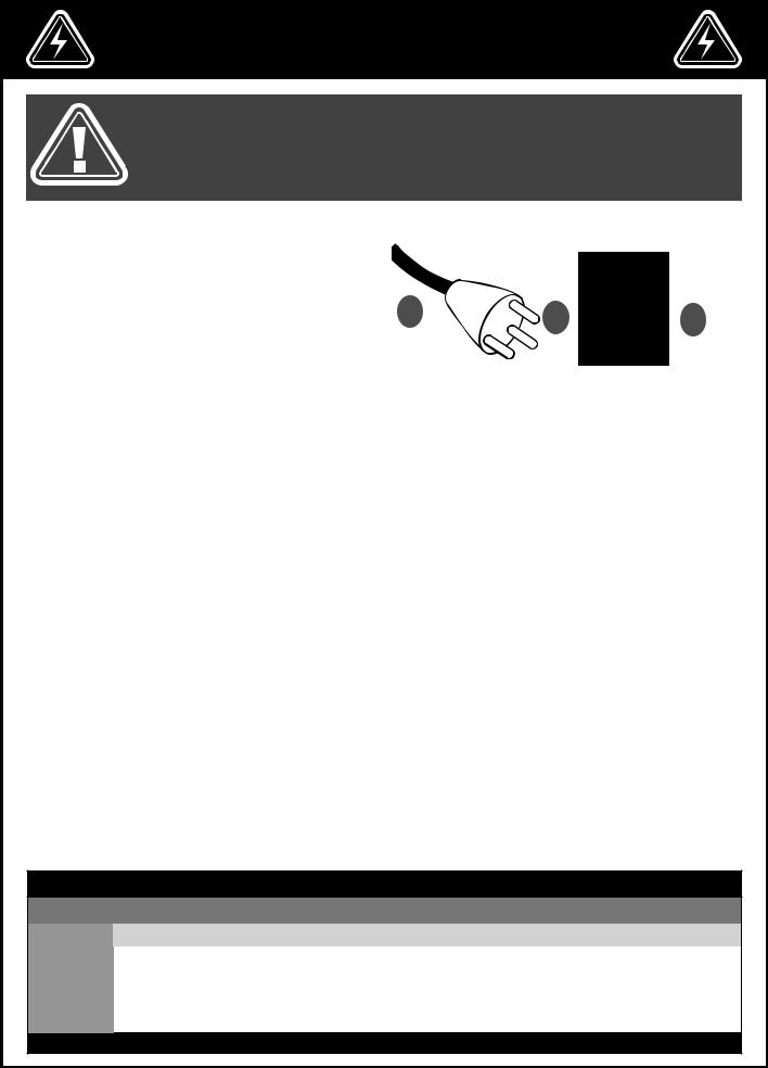
GROUNDING INSTRUCTIONS |
|
|
|
In the event of an electrical malfunction or short cir- |
|
|
|
|
|
|
|
cuit, grounding reduces the risk of electric shock to |
|
|
|
the operator. The motor of this machine is wired for |
|
|
|
220V single phase operation and is equipped with a |
A |
B |
|
3-conductor cord A and a 3-prong grounded plug B |
C |
||
to fit a matching grounding type receptacle C. DO |
|
|
|
NOT MODIFY THE PLUG PROVIDED ! If it will not fit your |
|
|
|
receptacle, have the proper receptacle installed by a |
|
|
|
qualified electrician. CHECK with a qualified electrician |
|
|
|
or service person if you do not completely understand |
|
|
|
these grounding instructions, or if you are not sure the |
|
|
|
tool is properly grounded. |
|
|
|
CIRCUIT CAPACITY |
|
|
|
|
|
|
Make sure that the wires in your circuit are capable of handling the amperage draw from your machine, as well as any other machines that could be operating on the same circuit. If you are unsure, consult a qualified electrician. If the circuit breaker trips or the fuse blows regularly, your machine may be operating on a circuit that is close to its amperage draw capacity. However, if an unusual amperage draw does not exist and a power failure still occurs, contact a qualified technician or our service department.
CONVERTING THE MOTOR TO 110V
Note: When converting motor voltage on a machine that is equipped with a magnetic switch, the switch contactor must also be changed out for one made for the appropriate voltage, as well as the thermal relay/circuit breaker and “power in” indicator light (if applicable). Failure to make these necessary modifications to the switch will lead to malfunction and permanent switch failure.
Should you need to convert your machine’s motor from 220V to 110V power, there is an electrical schematic drawing on the inside of the motor cover plate. Unless you are a qualified electrician, we do not recommend attempting this conversion on your own. If you choose to do so, you may risk serious personal injury, damage to the motor and voiding the warranty of your machine.We suggest you ask your local General International distributor to recommend qualified electricians in your area (or perhaps one of their own technicians) who can make this conversion properly and safely.
EXTENSION CORDS
The use of an extension cord is not generally recommended for 220V equipment. If you find it necessary, use only 3-wire extension cords that have 3-prong grounding plug and a matching 3-pole receptacle that accepts the tool’s plug. Repair or replace a damaged extension cord or plug immediately. If you find it necessary to use an extension cord with your machine make sure the cord rating is suitable for the amperage listed on the motor I.D. plate. An undersized cord will cause a drop in line voltage resulting in loss of power and overheating. The accompanying chart shows the correct size extension cord to be used based on cord length and motor I.D. plate amp rating. If in doubt, use the next heavier gauge. The smaller the number, the heavier the gauge.
TABLE - MINIMUM GAUGE FOR CORD
EXTENSION CORD LENGTH
AMPERES |
50 feet |
100 feet |
200 feet |
300 feet |
< 5 |
18 |
16 |
16 |
14 |
6 to 10 |
18 |
16 |
14 |
12 |
10 to 12 |
16 |
16 |
14 |
12 |
|
|
|
|
|
12 to 16 |
14 |
12 |
*NR |
*NR |
|
|
|
|
|
*NR = Not Recommended
6

IDENTIFICATION OF MAIN PARTS AND COMPONENTS
E F G H I
D

 J C
J C 
K
M
L
B
A
A. |
ENCLOSED STAND |
H. |
SANDING BELT |
B. |
STAND DOOR |
I. |
DUST PORT LOCK KNOB |
C. |
FRONT TABLE |
J. |
DUST PORT |
D. |
AUXILIARY END TABLE |
K. |
ON/OFF SWITCH |
E. |
BELT TRACKING ADJUSTMENT |
L. |
MOTOR |
F. |
MITER GAUGE |
M. SANDING HEAD TILT ADJUSTMENT |
|
G. |
BELT TENSION LEVER |
|
|
7

UNPACKING
Carefully unpack and remove the unit and its components from the box and check for missing or damaged items as per the list of contents below.
NOTE: PLEASE REPORT ANY DAMAGED OR MISSING ITEMS TO YOUR GENERAL® INTERNATIONAL DISTRIBUTOR IMMEDIATELY.
LIST |
OF CONTENTS |
QTY |
A. |
SIDE STAND PANEL.................................................................... |
2 |
B. |
REAR STAND PANEL ................................................................. |
1 |
C. |
BOTTOM STAND PANEL............................................................ |
1 |
D. |
STAND DOOR........................................................................... |
1 |
E. |
LOWER CROSSBAR (LARGER).................................................. |
1 |
F. |
UPPER CROSSBAR.................................................................... |
1 |
G. |
AUXILIARY TABLE....................................................................... |
1 |
H. |
SWITCH ASSEMBLY.................................................................... |
1 |
I. |
RIGHT DRUM GUARD............................................................... |
1 |
J. |
WORKPIECE STOP..................................................................... |
1 |
K. |
AUXILIARY TABLE SUPPORT BRACKET....................................... |
1 |
L. |
AUXILIARY TABLE SUPPORT ARM.............................................. |
1 |
M. |
RUBBER FEET............................................................................. |
4 |
N. |
DOOR LATCH ASSEMBLY.......................................................... |
1 |
O. |
LATCH STOPPER........................................................................ |
1 |
P. |
LEVER TENSION LEVER HANDLE............................................... |
1 |
Q. |
DRUM TRACKING ADJUSTMENT TOOL................................... |
1 |
R. |
LOCK KNOB (RIGHT DRUM GUARD)................................................ |
1 |
S. |
LOCK KNOB (LEFT DRUM GUARD).................................................. |
1 |
T. |
LOCK KNOB (TABLE FENCE).......................................................... |
2 |
U. |
TABLE FENCE*........................................................................... |
1 |
V. |
MITER GAUGE........................................................................... |
1 |
W. |
SANDING BELT* (NOT SHOWN)............................................... |
1 |
X. |
SANDING HEAD (NOT SHOWN).............................................. |
1 |
Y. |
HARDWARE TO MOUNT THE AUXILIARY TABLE........................................... |
1 |
Z. |
HARDWARE TO ASSEMBLE THE STAND.................................................... |
1 |
AA. HARDWARE TO SECURE THE RUBBER FEET................................................ |
1 |
|
AB. SUNK SCREW TO MOUNT THE LACTH STOPPER.......................................... |
2 |
|
AC. HARDWARE TO SECURE THE HEAD TO THE STAND...................................... |
1 |
|
AD. PHILLIPS SCREW TO SECURE THE SWTICH AND THE RIGHT GUARD (I)............... |
5 |
|
*The sanding belt and table fence are stored inside the sanding head to prevent damage in shipping
ADDITIONAL REQUIREMENTS FOR SET UP
A.PHILLIPS SCREWDRIVER
B.FLAT HEAD SCREWDRIVER
C.8, 10 & 12 MM WRENCHES
A B C E F
D
G
A
H I J K M N O P L
Q R S T U V
Y |
|
Z |
|
AA |
|
AB |
|
AC |
|
AD |
|
|
|
|
|
|
|
|
|
|
|
8
BASIC FUNCTIONS
This machine has been designed for sanding or polishing (removing kerf or pencil marks) on small workpieces, such as chair legs or stand doors.
The sanding belt can be tilted at any angle between 90º and 180º for bevelled pieces. Flat sanding, with the belt in the horizontal position (180º) is easier and safer for longer workpieces.
The auxiliary/end table can be installed on the end of the left side main table and used for sanding round or curved surfaces.
CLEANING
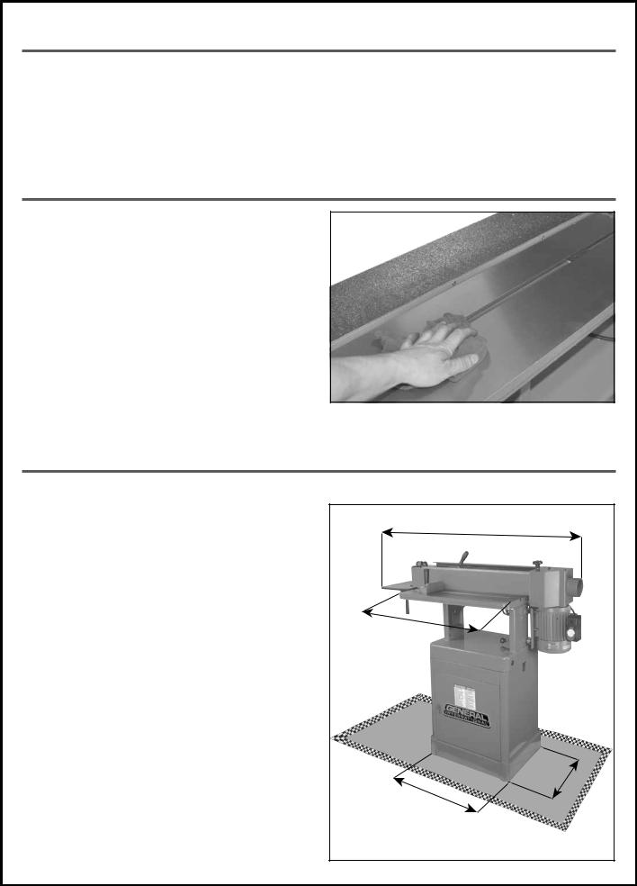
The protective coating on the table prevents rust from forming during shipping and storage. Remove it by rubbing with a rag dipped in kerosene, mineral spirits or paint thinner. (Dispose of potentially flammable solventsoaked rags according to manufacturer’s safety recommendations).
A putty knife, held flat to avoid scratching the surface, may also be used to scrape off the coating followed by clean-up with solvent. Avoid rubbing the machine’s painted surfaces, as many solvent-based products will remove paint.
To prevent rust, apply a light coating of paste wax or use regular applications of any after-market surface protectant or rust inhibitor.
PLACEMENT WITHIN THE SHOP / SAFETY ZONE
PLACEMENT WITHIN THE SHOP |
|
|
|
|
|
This machine should be installed and operated only on |
|
|
|
|
|
a solid, flat and stable floor that is able to support the |
|
|
50" |
|
|
weight of the machine (266 lbs - 121 kg) and the ope- |
|
|
|
||
|
|
|
|
||
rator. |
|
|
|
|
|
Using the dimensions shown as a guideline, plan for pla- |
|
|
|
|
|
cement within your shop that will allow the operator to |
|
|
|
|
|
work unencumbered and unobstructed by foot traffic |
|
|
|
|
|
(either passing shop visitors or other shop workers) or |
|
|
|
|
|
other tools or machinery. |
|
|
|
|
|
ESTABLISHING A SAFETY ZONE |
|
|
|
|
|
For shops with frequent visitors or multiple operators, it is |
|
|
|
|
|
advisable to establish a safety zone around shop ma- |
|
|
|
|
|
chinery. |
|
|
|
|
|
A clearly defined “no-go” zone on the floor around each |
|
|
|
|
|
machine can help avoid accidents that could cause in- |
|
|
|
|
|
jury to either the operator or the shop visitor. |
|
|
|
|
|
It is advisable to take a few moments to either paint (us- |
|
|
|
|
|
ing non-slip paint) or using tape, define on the floor the |
|
|
|
|
|
limits or perimeter of each machines safety zone. |
|
|
1 |
6 |
|
Take steps to ensure that all operators and shop visitors |
2 |
1 |
|||
|
|||||
|
|
||||
|
|
|
|||
|
|
|
|
||
are aware that these areas are off limits whenever a ma- |
|
" |
|
|
|
|
|
|
|
||
chine is running for everyone but the individual operat- |
|
|
|
|
|
ing the unit. |
|
|
|
|
9
 Loading...