


90-740

SETUP & OPERATION MANUAL
FEATURES
Head swivel 0° to 45º on heavy-duty cast-iron
slides.
Equipped with coolant system with built-in tank
and pump.
Magnetic switch and automatic shut-off.
Chip brush and safety guard included.
Adjustable blade tension and guide bearings.
Adjustable hydraulic down feed control.
7” X 10” METAL CUTTING BANDSAW
SPECIFICATIONS
• Cutting capacity at 90º (Rectangular)
7” x 10 1/4” (178 x 261 mm)
• Cutting capacity at 90º (Round)
7” (179 mm)
• Cutting capacity at 45º (Rectangular)
4 1/8” x 4 3/4” (105 x 121 mm)
• Cutting capacity at 45º (Round)
4 1/8” (105 mm)
• Blade size
3/4” x 0.035” x 93” (19 x 0.9 x 2360 mm)
• Blade speeds
73, 110, 150, 217 fpm
• Base dimensions (L x W)
52” x 25” (1320.8 x 635 mm)
• Overall dimensions (L x W x H)
50” x 41 3/8” x 47 1/4” (1270 x 1050 x 1200 mm)
• Motor (pre-wired 120 V)
1 HP, 120/240 V, 1Ph, 14/7 A
• Weight
462 lbs (210 kg)
Version #3_Revision #1 - December 2015
© Copyright General International
MODEL
#
90-740

GENERAL® INTERNATIONAL
8360 Champ-d’Eau, Montreal (Quebec) Canada H1P 1Y3
Telephone (514) 326-1161 • Fax (514) 326-5555 • www.general.ca
THANK YOU
for choosing this General® International model 90-740 7” x
10” Metal Cutting Bandsaw. This bandsaw has been carefully tested and inspected before
shipment and if properly used and maintained, will provide you with years of reliable service.
For your safety, as well as to ensure optimum performance and trouble-free operation, and to
get the most from your investment, please take the time to read this manual before assembling,
installing and operating the unit.
The manual’s purpose is to familiarize you with the safe operation, basic function, and
features of this bandsaw as well as the set-up, maintenance and identification of its parts and
components. This manual is not intended as a substitute for formal metalworking instruction,
nor to offer the user instruction in the craft of metalworking. If you are not sure about the safety
of performing a certain operation or procedure, do not proceed until you can confirm, from
knowledgeable and qualified sources, that it is safe to do so.
Once you’ve read through these instructions, keep this manual handy for future reference.
DISCLAIMER: The information and specifications
in this manual pertain to the unit as it was supplied
from the factory at the time of printing. Because we
are committed to making constant improvements,
General® International reserves the right to make
changes to components, parts or features of this unit
as deemed necessary, without prior notice and without
obligation to install any such changes on previously
delivered units. Reasonable care is taken at the factory
to ensure that the specifications and information in this
manual corresponds with that of the unit with which it
was supplied. However, special orders and “after factory”
modifications may render some or all information in
this manual inapplicable to your machine. Further,
as several generations of this model of Metal Cutting
Bandsaw and several versions of this manual may be
in circulation, if you own an earlier or later version of
this unit, this manual may not depict your unit exactly. If
you have any doubts or questions contact your retailer
or our support line with the model and serial number of
your unit for clarification.

GENERAL® INTERNATIONAL WARRANTY
All component parts of General® International and Excalibur by General International® products
are carefully inspected during all stages of production and each unit is thoroughly inspected upon
completion of assembly.
Limited Lifetime Warranty
Because of our commitment to quality and customer satisfaction, General® International agrees to
repair or replace any part or component which upon examination, proves to be defective in either
workmanship or material to the original purchaser for the life of the tool. However, the Limited Lifetime
Warranty does not cover any product used for professional or commercial production purposes nor
for industrial or educational applications. Such cases are covered by our Standard 2-year Limited
Warranty only. The Limited Lifetime Warranty is also subject to the “Conditions and Exceptions” as listed
below.
Standard 2-Year Limited Warranty
All products not covered by our lifetime warranty including products used in commercial, industrial
and educational applications are warranted for a period of 2 years (24 months) from the date of
purchase. General® International agrees to repair or replace any part or component which upon
examination, proves to be defective in either workmanship or material to the original purchaser during
this 2-year warranty period, subject to the “conditions and exceptions” as listed below.
To file a Claim
To file a claim under our Standard 2-year Limited Warranty or under our Limited Lifetime Warranty,
all defective parts, components or machinery must be returned freight or postage prepaid to
General® International, or to a nearby distributor, repair center or other location designated by
General® International. For further details call our service department at 1-888-949-1161 or your local
distributor for assistance when filing your claim.
Along with the return of the product being claimed for warranty, a copy of the original proof of purchase
and a “letter of claim” must be included (a warranty claim form can also be used and can be obtained,
upon request, from General® International or an authorized distributor) clearly stating the model and
serial number of the unit (if applicable) and including an explanation of the complaint or presumed
defect in material or workmanship.
CONDITIONS AND EXCEPTIONS:
This coverage is extended to the original purchaser only. Prior warranty registration is not required but
documented proof of purchase i.e. a copy of original sales invoice or receipt showing the date and
location of the purchase as well as the purchase price paid, must be provided at the time of claim.
Warranty does not include failures, breakage or defects deemed after inspection by
General® International to have been directly or indirectly caused by or resulting from; improper use,
or lack of or improper maintenance, misuse or abuse, negligence, accidents, damage in handling or
transport, or normal wear and tear of any generally considered consumable parts or components.
Repairs made without the written consent of General® International will void all warranty.

TABLE OF CONTENTS
Rules for safe operation ..................................................................................................... 5
Electrical requirements ...................................................................................................... 6
Identification of main parts and components .................................................................. 7
Unpacking .......................................................................................................................... 8
Basic functions ................................................................................................................... 8
Placement within the shop ................................................................................................ 9
Assembly instructions ................................................................................................... 9-12
Assembling the stand .................................................................................................................................... 9-10
Installing the support leg ................................................................................................................................. 10
Installing the transport handle ........................................................................................................................ 10
Installing the workpiece stop .......................................................................................................................... 10
Installing the pulley cover ................................................................................................................................11
Installing the front cover ...................................................................................................................................11
Installing the table for vertical cutting ............................................................................................................ 11
Installing the recovery tray filter ...................................................................................................................... 12
Basic adjustments and controls ................................................................................. 12-19
Connecting to a power source .......................................................................................................................12
Magnetic On/Off switch ................................................................................................................................... 12
Overload protection ......................................................................................................................................... 13
Removing/Installing a blade ..................................................................................................................... 13-14
Adjusting blade tension ................................................................................................................................... 15
Adjusting blade tracking ............................................................................................................................ 15-16
Squaring the blade to the work table ............................................................................................................ 16
Squaring the vise to the table/using the vise ........................................................................................... 16-17
Adjusting the cutting angle ............................................................................................................................. 17
Adjusting the blade guides ............................................................................................................................. 17
Adjusting the thrust bearings ........................................................................................................................... 18
Adjusting the blade guards ............................................................................................................................. 18
Changing speeds ............................................................................................................................................. 18
Speed selection chart ...................................................................................................................................... 19
Cutting feed rate ............................................................................................................................................... 19
Using the coolant pump .................................................................................................................................. 19
Operating Instructions ..................................................................................................... 20
Checklist before starting .................................................................................................................................. 20
Operations step-by-step ................................................................................................................................... 20
Maintenance .................................................................................................................... 21
Cleaning ............................................................................................................................................................ 21
Lubrication ......................................................................................................................................................... 21
Changing the belt and aligning the pulleys ................................................................................................. 21
Trouble shooting ...............................................................................................................................................22
Parts list & diagram .................................................................................................... 24-30
Contact information ........................................................................................................ 32

RULES FOR SAFE OPERATION
To help ensure safe operation, please take a moment to learn the machine’s applications and limitations,
as well as potential hazards. General
harmless for any injury that may result from the improper use of it’s equipment.
1. Do not operate the bandsaw when tired, distracted
or under the effects of drugs, alcohol or any medI cation that impairs reflexes or alertness.
2. The work area should be well lit, clean and free
of debris.
3. Keep children and visitors at a safe distance when
the bandsaw is in operation; do not permit them to
operate the bandsaw.
4. Childproof and tamper proof your shop and all ma chinery with locks, master electrical switches and
switch keys, to prevent unauthorized or unsupervised
use.
5. STAY ALERT! Give your work your undivided attention.
Even a momentary distraction can lead to serious
injury.
6. Fine particulate dust is a carcinogen that can be
hazardous to health. Work in a well-ventilated area.
Wear face, eye, ear, respiratory and body protec tion devices.
7. Do not wear loose clothing, gloves, bracelets,
necklaces or other jewelry while the bandsaw is in
operation.
8. Be sure that adjusting wrenches, tools, drinks and
other clutter are removed from the machine and/or
the table surface before operating.
9. Keep hands well away from the blade and all
moving parts. Use a brush, not hands, to clear away
chips and dust.
10. Adjust and position the blade guides before starting
to cut.
11. Adjust blade tension and tracking before starting to
cut.
12. Blade teeth must point down toward the table.
13. Be sure that the blade has gained full operating
speed before starting to cut.
14. Always use a clean, properly sharpened blade.
Dirty or dull blades are unsafe and can lead to
accidents.
®
International disclaims any real or implied warranty and hold itself
15. Use suitable workpiece support if the workpiece
does not have a flat surface.
16. Make sure the workpiece is securely held in place
in the vise.
17. Do not work on long stock without adequate sup port on the out feed end of the table.
18. Do not push or force stock into the blade. The band saw will perform better and more safely when work ing at the rate for which it was designed.
19. Avoid working from awkward or off balance posi tions. Do not overreach and keep both feet on floor.
20. Keep guards in place and in working order. If a
guard must be removed for maintenance or clean ing be sure it is properly re-attached before using
the saw again.
21. Never leave the machine unattended while it is run- ning or with the power on.
22. Use of parts and accessories NOT recommended
by General
malfunction or risk of injury.
23. Never stand on machinery. Serious injury could re sult if the tool is tipped over or if the cutting tool is
unintentionally contacted.
24. Always disconnect the saw from the power
source before servicing or changing accessories
such as blades, or before performing any mainte nance or cleaning, or if the machine will be left
unattended.
25. Make sure that the switch is in the “OFF” position
before plugging in the power cord.
26. Make sure the machine is properly grounded. If
equipped with a 3-prong plug it should be used with
a three-pole receptacle. Never remove the third
prong.
27. Do not use this bandsaw for other than
its intended use. If used for other purposes,
General® International disclaims any real or im plied warranty and holds itself harmless for any in jury, which may result from that use.
®
International may result in equipment
5
ELECTRICAL REQUIREMENTS
BEFORE CONNECTING THE MACHINE TO THE POWER SOURCE, VERIFY THAT THE VOLTAGE OF YOUR POWER SUPPLY CORRESPONDS WITH THE VOLTAGE SPECIFIED ON THE MOTOR I.D. NAMEPLATE. A POWER SOURCE WITH
GREATER VOLTAGE THAN NEEDED CAN RESULT IN SERIOUS INJURY TO THE USER AS WELL AS DAMAGE TO THE
MACHINE. IF IN DOUBT, CONTACT A QUALIFIED ELECTRICIAN BEFORE CONNECTING TO THE POWER SOURCE.
THIS TOOL IS FOR INDOOR USE ONLY. DO NOT EXPOSE TO RAIN OR USE IN WET OR DAMP LOCATIONS.
A
B
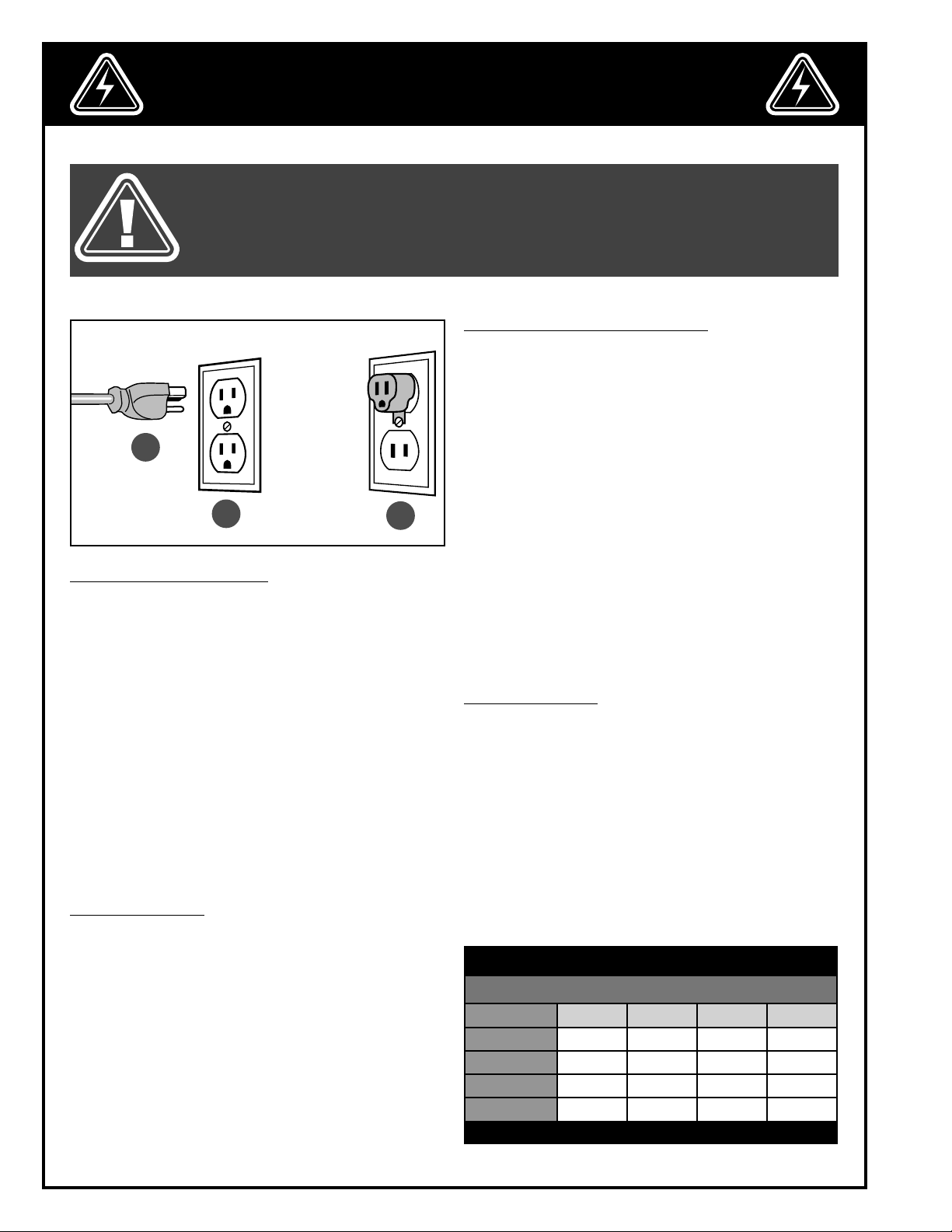
GROUNDING INSTRUCTIONS
In the event of an electrical malfunction or short circuit,
grounding reduces the risk of electric shock. The motor
of this machine is wired for 120 V single phase operation and is equipped with a 3-conductor cord and a
3-prong grounding plug A to fit a grounded type receptacle B. Do not remove the 3rd prong (grounding pin)
to make it fit into an old 2-hole wall socket or extension
cord. If an adaptor plug is used C, it must be attached
to the metal screw of the receptacle.
Note: The use of an adaptor plug is illegal in some
areas. Check your local codes. If you have any doubts
or if the supplied plug does not correspond to your
electrical outlet, consult a qualified electrician before
proceeding.
CIRCUIT CAPACITY
Make sure that the wires in your circuit are capable of
handling the amperage draw from your machine, as
well as any other machines that could be operating on
the same circuit. If you are unsure, consult a qualified
electrician. If the circuit breaker trips or the fuse blows
regularly, your machine may be operating on a circuit
that is close to its amperage draw capacity. However,
if an unusual amperage draw does not exist and a
power failure still occurs, contact a qualified technician
or our service department.
C
CONVERTING THE MOTOR TO 240V
Note: When converting motor voltage on a machine that
is equipped with a magnetic switch, the switch contactor
must also be changed out for one made for the appropriate voltage, as well as the thermal relay/circuit breaker
and “power in” indicator light (if applicable). Failure to
make these necessary modifications to the switch will lead
to malfunction and permanent switch failure.
Should you need to convert your machine’s motor
from 120 V to 240 V power, contact a qualified electrician. Unless you are a qualified electrician, we do
not recommend attempting this conversion on your
own. If you choose to do so, you may risk serious personal injury, damage to the motor and voiding the
warranty of your machine. We suggest you ask your
local General International distributor to recommend
qualified electricians in your area (or perhaps one of
their own technicians) who can make this conversion
properly and safely.
EXTENSION CORDS
If you find it necessary to use an extension cord with
your machine, use only 3-wire extension cords that have
3-prong grounding plug and a matching 3-pole receptacle that accepts the tool’s plug. Repair or replace a
damaged extension cord or plug immediately.Make
sure the cord rating is suitable for the amperage listed
on the motor I.D. plate. An undersized cord will cause a
drop in line voltage resulting in loss of power and overheating. The accompanying chart shows the correct
size extension cord to be used based on cord length
and motor I.D. plate amp rating. If in doubt, use the next
heavier gauge. The smaller the number, the heavier the
gauge.
TABLE - MINIMUM GAUGE FOR CORD
EXTENSION CORD LENGTH
AMPERES 50 feet 100 feet 200 feet 300 feet
< 5
6 to 10
10 to 12
12 to 16
*NR = Not Recommended
18 16 16 14
18 16 14 12
16 16 14 12
14 12 *NR *NR
6
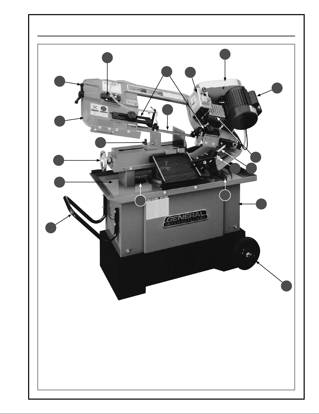
IDENTIFICATION OF MAIN PARTS AND COMPONENTS
D
A
K
P
N
E
I
I
G
B
C
H
O
M
J
S
L
R
A. BLADE TENSIONING HANDLE
B. BLADE ARM
C. VISE
D. VISE ADJUSTMENT HANDWHEEL
E. CONTROL BOX
F. WHEELS (2)
G. BLADE
H. GEAR BOX
I. MOTOR
J. WORKPIECE STOP
F
K. COOLANT RECOVERY TRAY
L. STAND
M. FEED RATE CONTROL CYLINDER
N. BLADE GUARDS (2)
O. FEED RATE CONTROL VALVE
P. BLADE TENSION INDICATOR
Q. PULLEY COVER
R. TRANSPORT HANDLE
S. RECOVERY TRAY FILTER
7
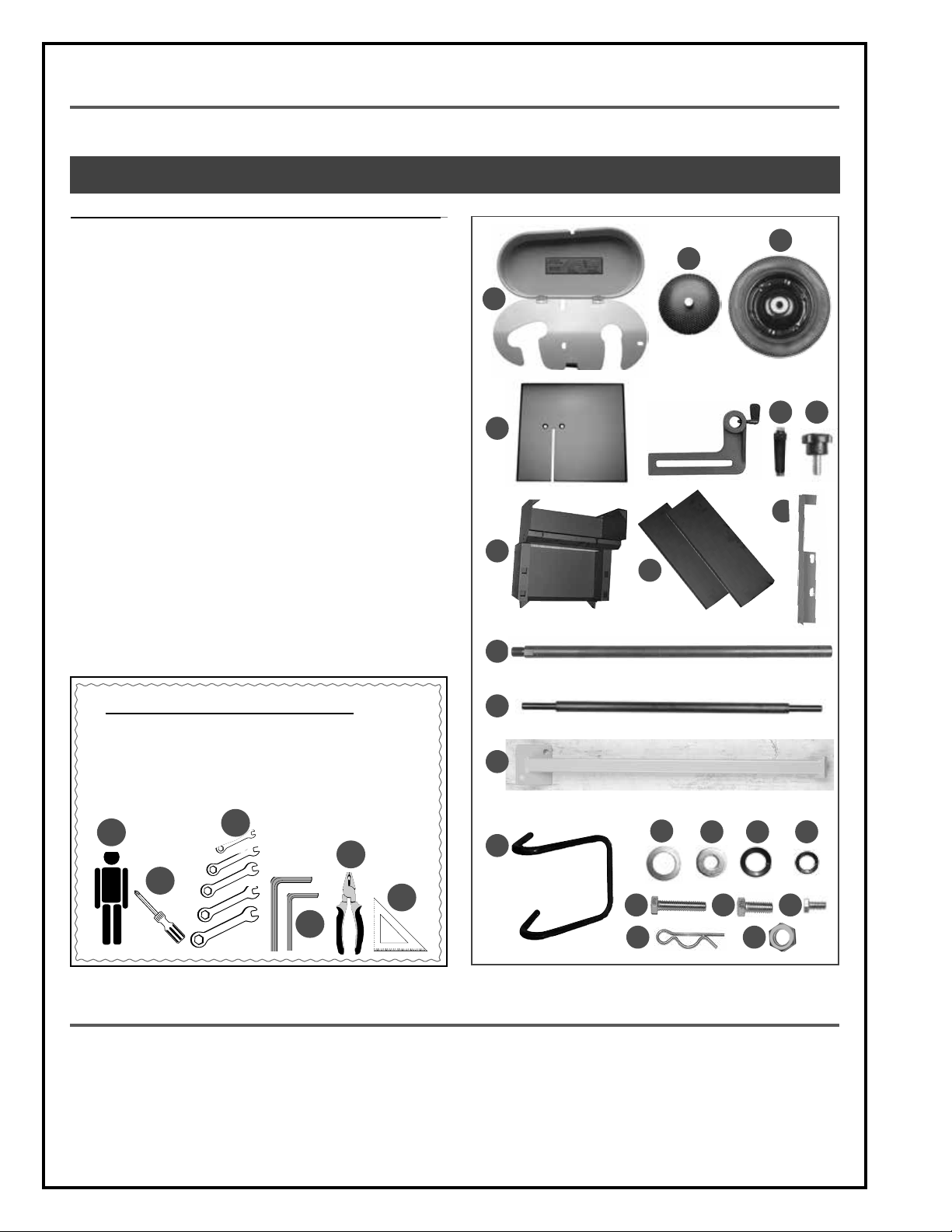
UNPACKING
Carefully unpack and remove the unit and its components from its box and check for missing or damaged items
as per the list of contents below.
NOTE: PLEASE REPORT ANY DAMAGED OR MISSING ITEMS TO YOUR GENERAL® INTERNATIONAL DISTRIBUTOR IMMEDIATELY.
LIST OF CONTENTS QTY
A. PULLEY COVER ......................................................................... 1
B. COOLANT FILTER ...................................................................... 1
C. WHEEL ..................................................................................... 2
D. VERTICAL CUTTING TABLE ....................................................... 1
E. WORKPIECE STOP BRACKET .................................................... 1
F. WORKPIECE STOP .................................................................... 1
G. PULLEY COVER LOCK KNOB ................................................... 1
H. STAND FRAME .......................................................................... 2
I. STAND PANELS ......................................................................... 2
J. WORKPIECE STOP BAR ............................................................ 1
K. WHEEL AXLE ............................................................................. 1
L. SUPPORT LEG ........................................................................... 1
M. TRANSPORT HANDLE ............................................................... 1
N. FLAT WASHER (WHEEL) ............................................................. 4
O. FLAT WASHER .......................................................................... 10
P. FLAT WASHER (HANDLE) .......................................................... 4
Q. FLAT WASHER (FRONT COVER, LEG) ....................................... 4
R. HEX BOLT (HANDLE) ................................................................ 4
S. HEX BOLT (TROLLEY) ................................................................ 4
T. HEX BOLT (FRONT COVER, LEG) ............................................. 4
U. COTTER PIN .............................................................................. 2
V. NUT (HANDLE) ......................................................................... 4
W. FRONT BLADE COVER ............................................................. 1
B
A
D
H
J
E
I
C
G
F
W
ADDITIONAL REQUIREMENTS FOR SET UP
A. EXTRA PERSON FOR HELP WITH LIFTING
B. PHILLIPS SCREWDRIVER
C. 10, 12,14, 17 & 20 MM WRENCHES
D. 4 & 6 MM ALLEN KEYS
E. PLIERS
F. SQUARE
A
C
E
K
L
M
N
O P Q
B
F
R
S T
D
U V
BASIC FUNCTIONS
This 7” x 10” horizontal metal cutting band saw is designed for both vertical and horizontal cutting in metalworking
and machine shops for cutting various types of bar stock, channel stock, piping, and thin-walled tubing.
With four blade speeds to accommodate a wide range of cutting needs, the unit features an automatic hydraulically controlled down feed with auto shutoff at the end of the cutting cycle.
The coolant system with built-in pump is designed to supply a continuous flow of liquid coolant to the cutting area
to prevent overheating of both the blade and the workpiece, providing cleaner cuts and prolonging blade life.
8
PLACEMENT WITHIN THE SHOP / SAFETY ZONE
THIS METAL CUTTING BANDSAW MODEL 90-740 IS HEAVY. DO NOT OVER-EXERT. A HOIST OR FORKLIFT WITH STRAPS
SHOULD BE USED TO LIFT THIS MACHINE. TO LIMIT THE RISK OF SERIOUS INJURY OR DAMAGE TO THE MACHINE,
ANY EQUIPMENT USED TO LIFT THIS MACHINE SHOULD HAVE A RATED CAPACITY IN EXCESS OF 462 LBS (210 KG).
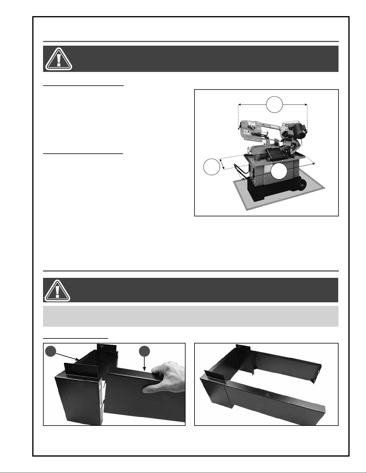
PLACEMENT WITHIN THE SHOP
This machine should be installed and operated only on
a solid, flat and stable floor that is able to support the
weight of the machine (462 lbs - 210 kg) and the operator. Using the dimensions shown as a guideline, plan for
placement within your shop that will allow the operator
to work unencumbered and unobstructed by foot traffic (either passing shop visitors or other shop workers) or
other tools or machinery.
ESTABLISHING A SAFETY ZONE
For shops with frequent visitors or multiple operators,
it is advisable to establish a safety zone around shop
machinery. A clearly defined “no-go” zone on the floor
around each machine can help avoid accidents that
could cause injury to either the operator or the shop
visitor.
It is advisable to take a few moments to either paint (using non-slip paint) or using tape, define on the floor the
limits or perimeter of each machines safety zone. Take
steps to ensure that all operators and shop visitors are
aware that these areas are off limits whenever a machine is running for everyone but the individual operating the
unit.
16"
50"
40"
ASSEMBLY INSTRUCTIONS
BEFORE ASSEMBLING, MAKE SURE THAT THE SWITCH IS IN THE “OFF” POSITION AND THAT THE POWER CORD IS
UNPLUGGED. DO NOT PLUG IN OR TURN ON THE MACHINE UNTIL YOU HAVE COMPLETED THE ASSEMBLY AND
INSTALLATION STEPS DESCRIBED IN THIS SECTION OF THE MANUAL.
Tip: you will need to lift the machine in order to install it on its stand. Due to the weight of the machine, adequate lifting equipment such as a jack, hoist, or forklift with straps is required. Any equipment used to lift the machine must have a minimum
weight capacity of 462 lbs (210 kg).
ASSEMBLING THE STAND
A B
1. Position the left frame A as shown and attach the
front panel B by sliding its two tabs inside the panel
as shown.
2. Repeat with the rear panel as shown.
9
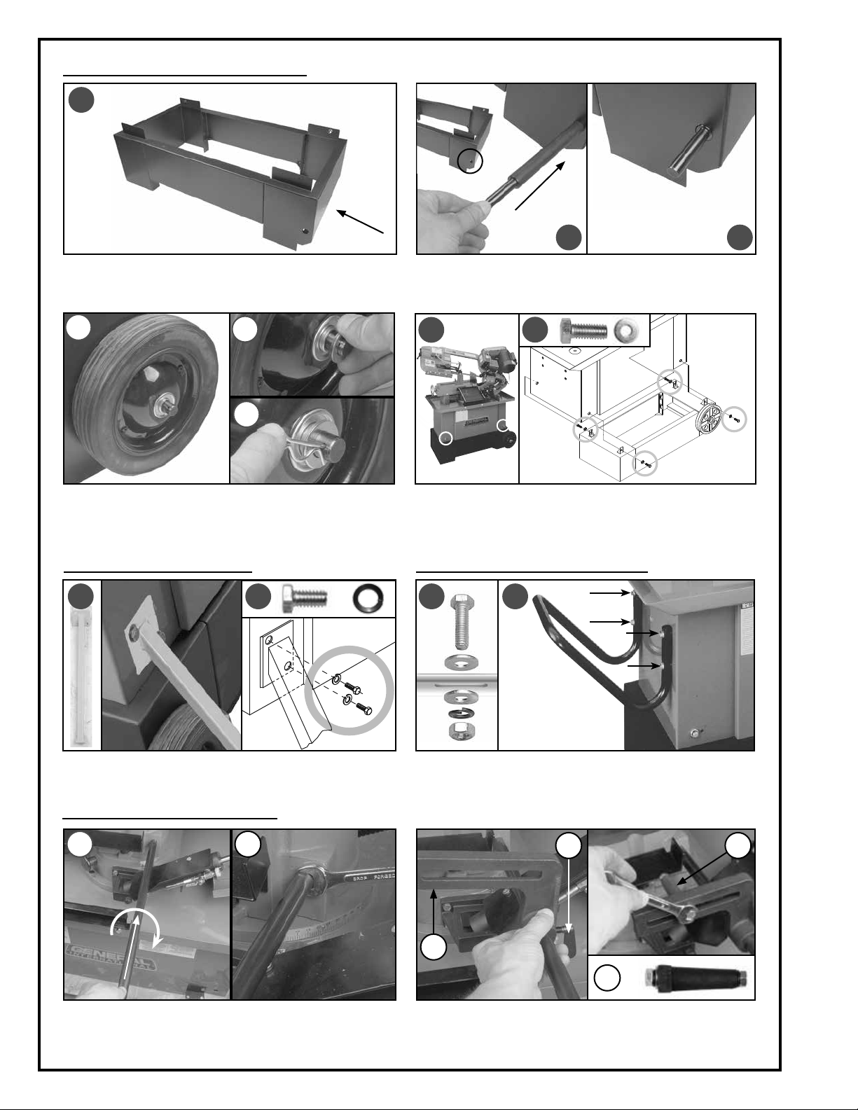
ASSEMBLING THE STAND (CONTINUED)
115(2)
114(2)
116
117
119
120
121
118(2)
92(2)
93(2)
13
21(4)
21(4)
A
B
3. Attach the right frame to the rest of the stand as
shown A.
D
E
4. Install the axle B as shown.
Note: The ends of the axle should protrude beyond the sides
of the machine C.
G
H
F
5. Install the wheels on the ends of the axle D. Slide a
flat washer onto the axle and against each wheel
E and then insert a cotter pin (provided) through
the holes on each end as shown F.
INSTALLING THE SUPPORT LEG INSTALLING THE TRANSPORT HANDLE
I K LJ
6. Lift the machine and install the trolley underneath
G. Attach the machine to the trolley using the four
bolts and flat washers H with a 14 mm wrench.
C
Attach the support leg I on the rear left corner of the
machine using the two bolts and spring washers J.
INSTALLING THE WORKPIECE STOP
M
N
1. Screw the stop bar into its mounting hole M and
tighten it with a 17 mm wrench to secure it in place.
10
Install the handle L on the machine cabinet using the
hardware in the order shown K.
P
Q
O
Q
2. Slide the workpiece stop bracket onto the bar as shown
O and tighten the thumbscrew P to secure it in place.
Install the stop using a 12 mm wrench as shown Q.
 Loading...