


15-010 M1

FEATURES
Tables can be adjusted up or down for full
belt use.
Front table can be inclined left or right.
Innovative hinged dust hood accommo-
dates oversized stock.
Easy adjustment of abrasive belt tension
with one knob only.
Graphite backing reduces belt friction for
longer belt life.
Single knob tracking control.
Auxiliary table allows curved sanding.
Heavy steel base ensures a solid stable
platform while sanding.
Dynamically balanced 7’’rubber drive
roller and crowned 3’’idler roller to ensure
solid belt tracking.
Magnetic 2-step safety switch to prevent
unwanted or unintentional start-up is
equipped with an extra-large easy access
stop panel and a lock-out key to prevent
unauthorized use of the sander.
SPECIFICATIONS
BELT SIZE
6" X 108" (152 x 2743 MM)
FRONT
TABLE SIZE (L X W)
7 3⁄4”x 37’’(197 x 940 MM)
A
UXILIARY T
ABLE SIZE (L X W)
11 3⁄4”x 19’’(299 x 483 MM)
DUST CHUTE OUTLET
4" (102 MM)
BEL
T SPEED
3150 FPM
B
ASE DIMENSIONS (L X W)
42”x 16 1⁄2” (1067 x 419 MM)
MO
TOR
M1 2 HP, 220 V, 1 PH, 14 A
M2 2 HP, 220 V, 3 PH, 6 A
M3 2 HP, 600 V, 3 PH, 2.5 A
WEIGHT
462 LBS (210 KG)
SETUP & OPERATION MANUAL
MODEL
#15-010 M1
6" X 108" VERTICAL EDGE BELT SANDER
VERSION 2_REVISION 1 - JUNE 08/10 (19115210)
© Copyright General® International 06/2010
THANK YOU
for choosing this General®International model 15-010 6" X 108"
Ver tical Edge Belt Sander. This sander has been carefully tested and inspected before shipment and if properly used and maintained, will provide you with years of reliable service. To
ensure optimum performance and trouble-free operation, and to get the most from your
investment, please take the time to read this manual before assembling, installing and operating the unit.
The manual’s purpose is to familiarize you with the safe operation,basic function, and features
of this sander as well as the set-up, maintenance and identification of its par ts and components. This manual is not intended as a substitute for formal woodworking instruction, nor to
offer the user instruction in the craft of woodworking. If you are not sure about the safety of
performing a certain operation or procedure, do not proceed until you can confirm, from
knowledgeable and qualified sources,that it is safe to do so.
Once you’ve read through these instructions, keep this manual handy for future reference.
Disclaimer:
The information and specifications in this
manual pertain to the unit as it was supplied from the
factory at the time of printing. Because we are committed to making constant improvements, General
®
International reserves the right to make changes to
components, parts or features of this unit as deemed
necessary,without prior notice and without obligation to
install any such changes on previously delivered units.
Reasonable care is taken at the factory to ensure that
the specifications and information in this manual corres-
ponds with that of the unit with which it was supplied.
However, special orders and “after factory” modifications may render some or all information in this manual
inapplicable to your machine. Further,as several generations of this model of sander and several versions of
this manual may be in circulation, if you own an ear lier
or later version of this unit, this manual may not depict
your machine exactly. If you have any doubts or questions contact your retailer or our support line with the
model and serial number of your unit for clarification.
GENERAL® INTERNATIONAL
8360 Champ-d’Eau, Montreal (Quebec) Canada H1P 1Y3
Telephone (514) 326-1161 • Fax (514) 326-5555 • www.general.ca
GENERAL®& GENERAL®INTERNATIONAL WARRANTY
All component parts of General®, General® International and Excalibur by General
International ® products are carefully inspected during all stages of production and each unit
is thoroughly inspected upon completion of assembly.
Limited Lifetime
Warranty
Because of our commitment to quality and customer satisfaction, General® and General®
International agree to repair or replace any part or component which upon examination,
proves to be defective in either workmanship or material to the original purchaser for the life
of the tool.
However, the Limited Lifetime Warranty does not cover any product used for professionnal or commercial production purposes nor for industrial or educational applications.
Such cases are covered by our Standard 2-year Limited Warranty only. The Limited Lifetime
Warranty is also subject to the “Conditions and Exceptions” as listed below.
Standard 2-Year Limited Warranty
All products not covered by our lifetime warranty including products used in commercial,
industrial and educational applications are w arranted f or a period of 2 years (24 months) from
the date of purchase. General® and General® International agree to repair or replace any
part or component which upon examination, proves to be defective in either workmanship or
material to the original purchaser during this 2-year warranty period, subject to the “conditions
and exceptions”as listed below.
T
o file a Claim
To file a claim under our Standard 2-year Limited Warranty or under our Limited Lifetime
Warranty, all defective parts , components or machiner y must be returned freight or postage
prepaid to General® International, or to a nearby distributor, repair center or other location
designated by General® International. For further details call our service department at 1-888949-1161 or your local distributor for assistance when filing your claim.
Along with the return of the product being claimed for warranty, a copy of the original proof
of purchase and a “letter of claim”must be included (a w arranty claim form can also be used
and can be obtained,upon request,from General® International or an authorized distributor)
clearly stating the model and serial number of the unit (if applicable) and including an explanation of the complaint or presumed defect in material or workmanship.
CONDITIONS AND EXCEPTIONS:
This coverage is extended to the original purchaser only. Prior warranty registration is not
required but documented proof of purchase i.e. a copy of original sales invoice or receipt
showing the date and location of the purchase as well as the purchase price paid, must be
provided at the time of claim.
Warranty does not include f ailures,breakage or defects deemed after inspection by General®
or General® International to have been directly or indirectly caused by or resulting from:
improper use, or lack of or improper maintenance, misuse or abuse, negligence, accidents,
damage in handling or transport, or normal wear and tear of any generally considered consumable parts or components .
Repairs made without the written consent of General® Interna tionallwill void all warranty.
TABLE OF CONTENTS
SAFETY RULES . . . . . . . . . . . . . . . . . . . . . . .5
ELECTRICAL REQUIREMENTS . . . . . . . . . . . . . .6
Electrical connections . . . . . . . . . . . . . . . . . . . . . . .6
Grounding instructions . . . . . . . . . . . . . . . . . . . . . . .6
Circuit capacity . . . . . . . . . . . . . . . . . . . . . . . . . . . . .6
Check power connection for polarity . . . . . . . . . .6
Extension cords . . . . . . . . . . . . . . . . . . . . . . . . . . . . .6
IDENTIFICATION OF MAIN PARTS AND COMPONENTS . . . . . . . . . . . . . . . . . . . . . . . . . . . .
7
BASIC FUNCTIONS . . . . . . . . . . . . . . . . . . . .8
UNPACKING . . . . . . . . . . . . . . . . . . . . . . . .8
List of contents . . . . . . . . . . . . . . . . . . . . . . . . . . . . . .8
PLACEMENT WITHIN THE SHOP / ESTABLISHING
A SAFETY ZONE . . . . . . . . . . . . . . . . . . . . . . .
9
LIFTING AND HANDLING THE MACHINE . . . . . . .9
ASSEMBLY INSTRUCTIONS . . . . . . . . . . . . . .10
Reposition the auxiliary table mounting bracket .10
Install the tables . . . . . . . . . . . . . . . . . . . . . . . . . . . .10
Install the dust hood/end guard . . . . . . . . . . . . . .11
Connecting to a dust collector . . . . . . . . . . . . . . .11
BASIC ADJUSTMENTS & CONTROLS . . . . . . . .11
Connecting to a power source . . . . . . . . . . . . . . .11
Magnetic safety switch . . . . . . . . . . . . . . . . . . . . . .12
Overload protection/Circuit breaker . . . . . . . . . .12
Front table height adjustment . . . . . . . . . . . . . . . .12
Front table inclination adjustment . . . . . . . . . . . .13
Auxiliary table height adjustment . . . . . . . . . . . . .13
Sanding belt tracking adjustment . . . . . . . . . . . . .13
MAINTENANCE . . . . . . . . . . . . . . . . . . . . . .14
Periodic maintenance . . . . . . . . . . . . . . . . .14
Required maintenance . . . . . . . . . . . . . . . .14
Replacement of the sanding belt . . . . . . . . . . . . .14
Replacement of the graphite coating on the
platen . . . . . . . . . . . . . . . . . . . . . . . . . . . . . . . . . . . .15
Steel platen adjustment . . . . . . . . . . . . . . . . . . . . .16
Spring fatigue compensation adjustment . . . . . .16
Lubrication . . . . . . . . . . . . . . . . . . . . . . . .16
RECOMMENDED OPTIONAL ACCESSORIES . . . .17
PARTS LIST AND DIAGRAMS . . . . . . . . . . . . .18
CONTACT INFORMATION . . . . . . . . . . . . . . . .22
RULES FOR SAFE OPERATION
To help ensure safe operation, please take a moment to learn the machine’s applications and limitations, as well as potential hazards. General® International disclaims any real or implied warranty and holds itself harmless for any injury that
may result from improper use of its equipment.
1. Do not operate the sander when tired, dis tracted,
or under the effects of drugs, alcohol or any medication that impairs reflexes or alertness.
2. The working area should be well lit, clean and free
of debris.
3. Keep children and visitors at a safe distance when
the sander is in operation; do not permit them to
operate the sander.
4. Childproof and tamper proof your shop and all
machinery with locks, master electrical switches
and switch keys, to prevent unauthorized or unsupervised use.
5. Stay alert! Give your work your undivided attention.Even a momentary distraction can lead to serious injury.
6. Fine particula te dust is a carcinogen that can be
hazardous to health. Work in a well-ventilated area
and wear eye, ear and respiratory protection
devices.
7. Do not operate this sander without an adequate dust collection system properly installed and
running. Operating this sander without adequate
dust collection can lead to equipment malfunction
or dangerous situations for the operator or other
individuals in the workshop.
8. Do not wear loose clothing,gloves,bracelets, necklaces or other jewelry while the sander is in operation. Wear protective hair covering to contain long
hair and wear non-slip footwear.
9. Be sure that adjusting wrenches, tools, drinks and
other clutter are removed from the machine and/or
the feed table surface before operating.
10. Keep hands well away from the sanding belts and
all moving parts. Use a brush, not hands, to clear
away sanding dust.
11. Be sure sanding belts are securely installed on the
sanding drums.
12. Do not operate the sander if the sanding belts are
damaged or badly worn.
13. Do not push or force the workpiece into the sander.
The machine will perform better and more safely
when working at the feed rate for which it was
designed.
14. Avoid wor king from awkward or off balance positions.Do not overreach and keep both feet on floor.
15. To minimize risk of injury in the event of workpiece
kickback,never stand directly in-line with the sanding belt or in the potential kickback path of the
work piece.
16. Keep guards in place and in working order. If a
guard must be removed for maintenance or cleaning, be sure it is properly re-attached before using
the tool again.
17. Never leave the machine unattended while it is running or with the power on.
18. Use of parts and accessories NOT recommended
by
GENERAL® INTERNATIONAL
may result in equip-
ment malfunction or risk of injury.
19. Never stand on the machine. Serious injury could
occur if the sander is tipped over or if the sanding
belt is unintentionally contacted.
20. Always disconnect the tool from the power source
before servicing, changing accessories or sanding
belts, or before performing any maintenance or
cleaning, or if the machine will be left unattended.
21. Make sure that switch is in “OFF” position before
plugging in the power cord.
22. Make sure the tool is properly grounded. If equipped with a 3-prong plug it should be used with a
three-pole receptacle. Never remove the third
prong.
23. Do not use the sander for other than its intended use. If used for other purposes,
GENERAL® INTER
NATIONAL
disclaims any real implied warranty and
holds itself harmless for any injury,which may result
from that use.
5
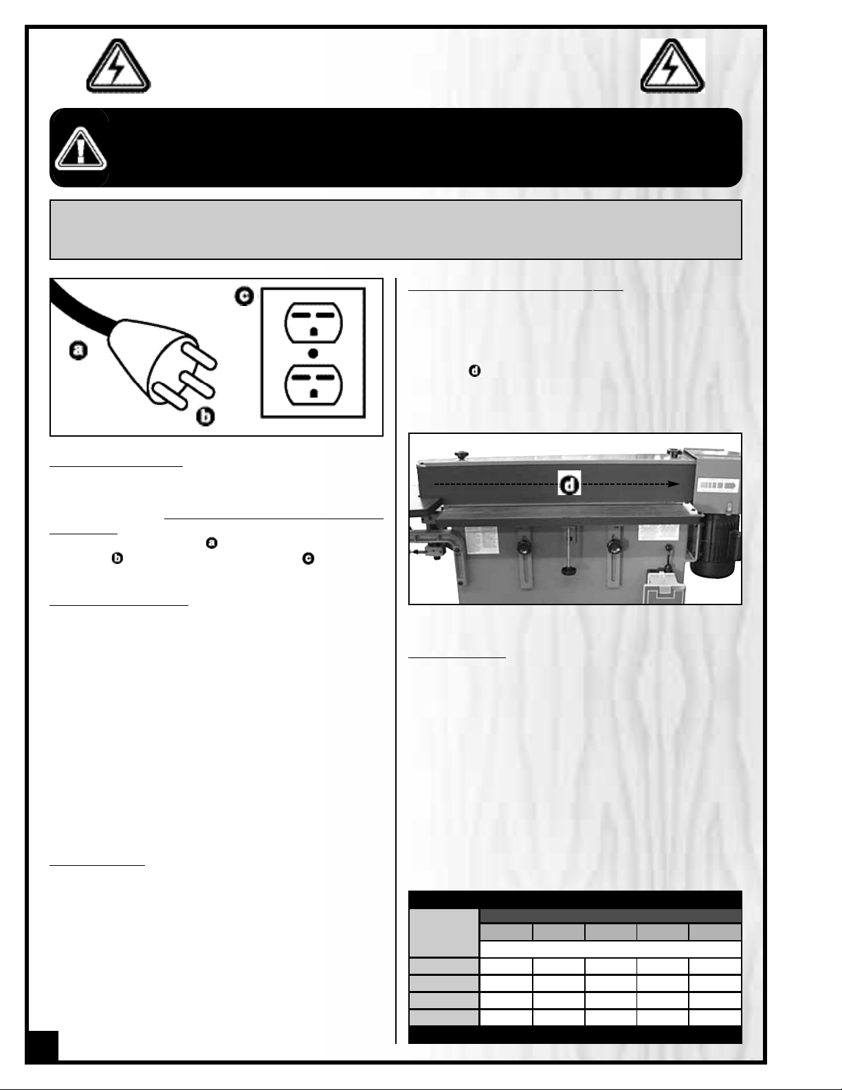
ELECTRICAL CONNECTIONS
Both a manual circuit breaker (or similar de vice) as well
as an electrical plug (similar to the one shown) are recommended and should be installed b
y a qualified
electr
ician
. Use locally approved wire that includes a
separate grounding wire , and a 3 prong grounding
type plug with a matching receptacle .
GROUNDING INSTRUCTIONS
In the event of an electrical malfunction or short circuit,
grounding reduces the risk of electric shock to the operator. The motor of the “M1” model of this machine is
wired for 220V single phase operation.As with many stationary industr ial type machines, because each installation situation is unique, this sander is supplied without
a plug. The ins tallation of an appropriate plug must be
performed by a qualified electrician.The machine must
be connected to an electrical source using a power
cord that has a grounding wire, which must also be
properly connected to the grounding prong on the
plug.The outlet must be properly installed and grounded and all electrical connections must be made in
accordance with all local codes and regulations.
CIRCUIT CAPACITY
Make sure that the wires in your circuit are capable of
handling the amperage draw from your machine, as
well as any other machines that could be operating on
the same circuit. If you are unsure, consult a qualified
electrician. If the circuit breaker trips or the fuse blows
regularly, your machine may be operating on a circuit
that is close to its amperage draw capacity.However, if
an unusual amperage draw does not exist and a
power failure still occurs,contact a qualified technician
or our service depar tment.
BEFORE CONNECTING THE MACHINE TO THE POWER SOURCE,VERIFY THAT THE VOLTAGE OF YOUR POWER SUPPLY CORRESPONDS
WITH THE VOLTAGE SPECIFIED ON THE MOTOR I.D. NAMEPLATE. A POWER SOURCE WITH GREATER VOLTAGE THAN NEEDED CAN
RESULT IN SERIOUS INJURY TO THE USER AS WELL AS DAMAGE TO THE MACHINE. IF IN DOUBT ,CONTACT A QUALIFIED ELECTRICIAN
BEFORE CONNECTING TO THE POWER SOURCE.
THIS TOOL IS FOR INDOOR USE ONLY. DO NOT EXPOSE TO RAIN OR USE IN WET OR DAMP LOCATIONS.
CHECK POWER CONNECTION FOR POLARIT
Y
After the wires have been connected it is necessary to
check if they are connected for proper polarity.
Press the start (green) button. The sanding belt should
move left to right as observed from the front of the
machine . If the sanding belt direction of rotation is
incorrect,press the stop (red) button and disconnect the
sander from power. Switch any two of the three wires at
L1, L2,L3 (for M2 and M3).
EXTENSION CORDS
The use of an extension cord is not generally recommended for 220V equipment. If you find it necessary,
use only 3-wire extension cords that have 3-prong
grounding plug and a matching 3-pole receptacle that
accepts the tool’s plug. Repair or replace a damaged
extension cord or plug immediately.
Make sure the cord rating is suitable for the amperage
listed on the motor I.D. plate. An undersized cord will
cause a drop in line voltage resulting in loss of power
and overheating. The accompanying chart shows the
correct size extension cord to be used based on cord
length and motor I.D. plate amp rating. If in doubt, use
the next heavier gauge. The smaller the number, the
heavier the gauge.
6
NOTE: VOLTAGE REQUIREMENTS AND AMPERAGE DRAW FOR M2 & M3 3-PHASE MOTORS MAY NOT BE FULLY
DESCRIBED IN THIS MANUAL. FOR COMPLETE ELECTRICAL REQUIREMENTS REFER TO THE MOTOR I.D. NAME PLATE ON
THE MACHINE. IF IN DOUBT CONSULT A LICENSED QUALIFIED ELECTRICIAN BEFORE PROCEEDING.
ELECTRICAL REQUIREMENTS
TABLE - MINIMUM GAUGE FOR CORD
AMPERE
RATING
TOTAL LENGTH OF CORD IN FEET
220 VOLTS 50 FEET 100 FEET 200 FEET 300 FEET
AWG
< 5
------->
18 16 16 14
6 TO 10
------->
18 16 14 12
10 TO 12
------->
16 16 14 12
12 TO 14
------->
14 12 * NR * NR
* NR = Not Recommended
6" X 108" VERTICAL EDGE BELT SANDER
15-010 M1
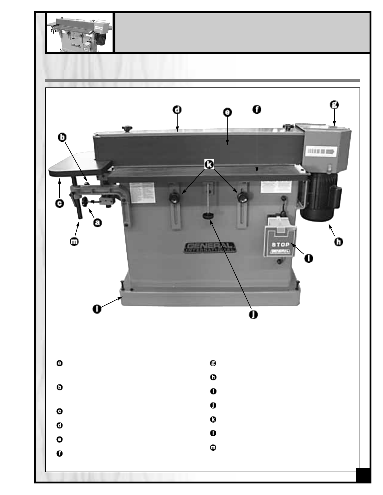
IDENTIFICATION OF MAIN PARTS AND COMPONENTS
SANDING BELT TRACKING ADJUSTMENT
KNOB
SANDING BELT TENSION ADJUSTMENT
KNOB
AUXILIARY TABLE
TOP COVER
SANDING BELT
FRONT TABLE
END GUARD/DUST HOOD
MOTOR ASSEMBLY
ON/OFF SWITCH
FRONT TABLE HEIGHT ADUSTMENT KNOB
FRONT TABLE HEIGHT LOCK KNOBS
BASE
AUXILIARY TABLE HEIGHT ADJUSTMENT
LOCKING LEVER
7
 Loading...