


AOH12LM
General AOH12LM, ASH12LMACW, AOH12LMAK2, AOH7LM, ASH7LMACW Technical Manual
...
R410A
D2D_MU009E/01
2006.10.25
1.
MULTI TYPE : 2ROOM TYPE
AR 9LUAB AB 14LBAJ
AR 12LUAD AB 18LBAJ
AR 14LUAD
AR 18LUAD
AS 7LMACW
AU 12LBAB AS 9LMACW
AU 14LBAB AS 12LMACW
AU 18LBAB AS 18LBAJ
INDOOR UNIT
- (01 - 01) -
MULTI TYPE
2ROOM TYPE
MULTI TYPE
2ROOM TYPE
MODELS :
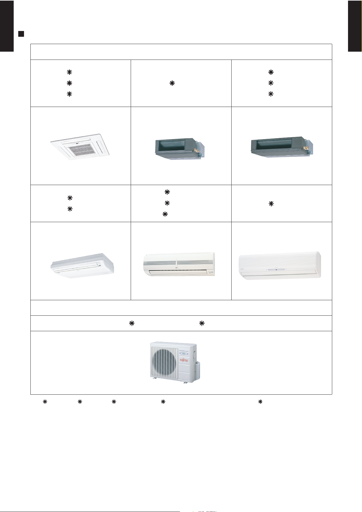
1. FEATURE
INDOOR UNIT
AU 12LBAB
AU 14LBAB
AU 18LBAB
AO 18LMAK2 / AO 24LMAM2
AB 14LBAJ
AB 18LBAJ
AS 18LBAJ
AR 12LUAD
AR 14LUAD
AR 18LUAD
OUTDOOR UNIT
Cassette Type (Compact)
Universal Type
Duct Type
Wall Mounted Type
AS 7LMACW
AS 9LMACW
AS 12LMACW
AR 9LUAB
Duct Type (Small)
Wall Mounted Type (Compact)
AU 18L, AR 18L, AB 18L, and AS 18L cannot connect to AO 18L2
- (01 - 02) -
MULTI TYPE
2ROOM TYPE
MULTI TYPE
2ROOM TYPE
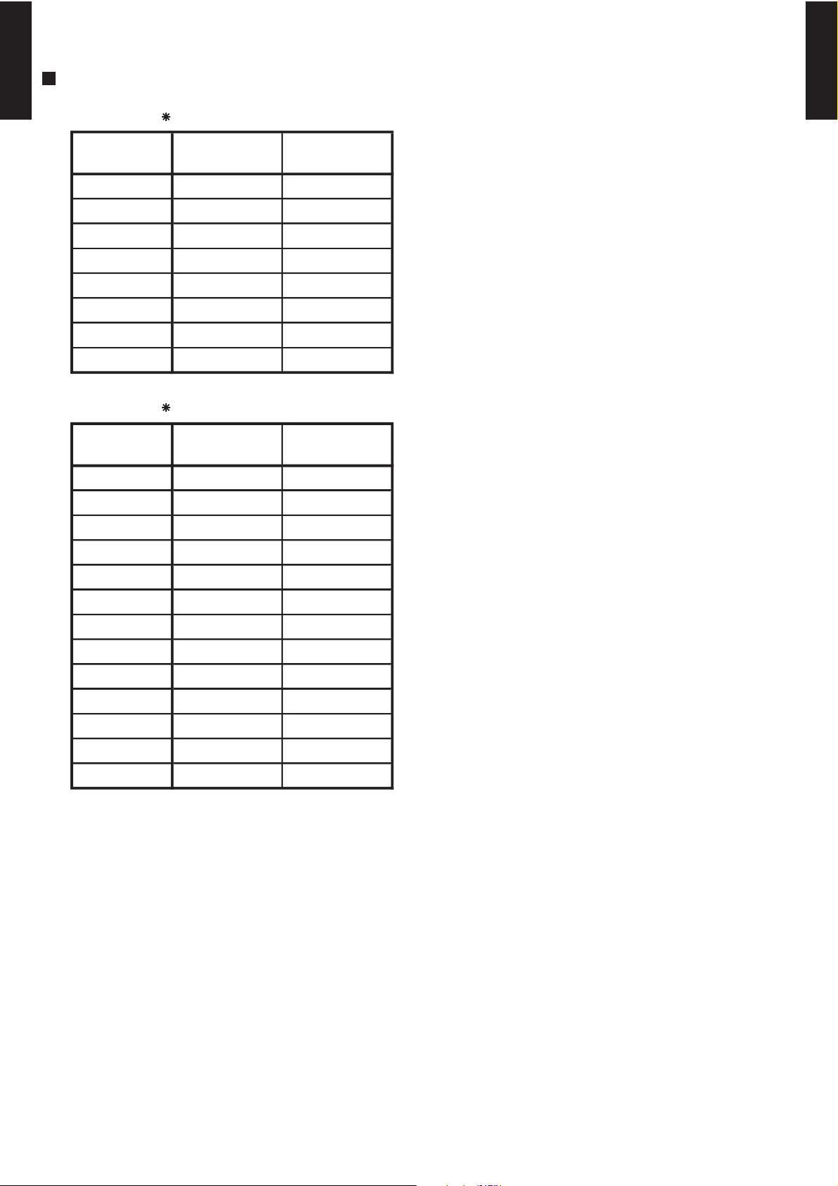
INDOOR UNIT CONNECTION PATTERN
MODEL : AO 18L2
MODEL : AO 24L2
CONNECTION
PATTERN
No.1
Indoor unit
No.2
Indoor unit
1 7,000 7,000
2 7,000 9,000
3 7,000 12,000
4 7,000 14,000
5 9,000 9,000
6 9,000 12,000
7 9,000 14,000
8 12,000 12,000
CONNECTION
PATTERN
No.1
Indoor unit
No.2
Indoor unit
1 7,000 7,000
2 7,000 9,000
3 7,000 12,000
4 7,000 14,000
5 7,000 18,000
6 9,000 9,000
7 9,000 12,000
8 9,000 14,000
9 9,000 18,000
10 12,000 12,000
11 12,000 14,000
12 12,000 18,000
13 14,000 14,000

- (01 - 03) -
MULTI TYPE
2ROOM TYPE
MULTI TYPE
2ROOM TYPE
1-2-1. INDOOR UNIT
MODELS : AS 7L, AS 9L, AS 12L, AS 18L
1-2. FEATURE
When the air conditioner power was temporarily turned off by a power failure etc.
It restarts automatically after the power recovers.
(Operated by setting before the power failure.)
Auto restart
1-2-2. OUTDOOR UNIT
MODELS : AO 18L2, AO 24L2
When the current contacted is insufficient, you can change the current capacity.
Current capacity setting
The Remote control unit signal code can be changed by four patterns.
Remote control unit signal code setting
MODELS : AR 9L, AR 12L, AR 14L, AR 18L
When the air conditioner power was temporarily turned off by a power failure etc.
It restarts automatically after the power recovers.
(Operated by setting before the power failure.)
Auto restart
In case of installing in high static, you can maximize(minimize) air flow and noise.
High static pressure function setting
You can control sub fan by synchronization with fan operation of indoor unit.
Fresh air output
MODELS : AU 12L, AU 14L, AU 18L
When the air conditioner power was temporarily turned off by a power failure etc.
It restarts automatically after the power recovers.
(Operated by setting before the power failure.)
Auto restart
The Remote control unit signal code can be changed by four patterns.
Remote control unit signal code setting
MODELS : AB 14L, AB 18L
When the air conditioner power was temporarily turned off by a power failure etc.
It restarts automatically after the power recovers.
(Operated by setting before the power failure.)
Auto restart
The Remote control unit signal code can be changed by four patterns.
Remote control unit signal code setting
- (01 - 04) -
MULTI TYPE
2ROOM TYPE
MULTI TYPE
2ROOM TYPE
2. REMOTE CONTROLLER
2-1.
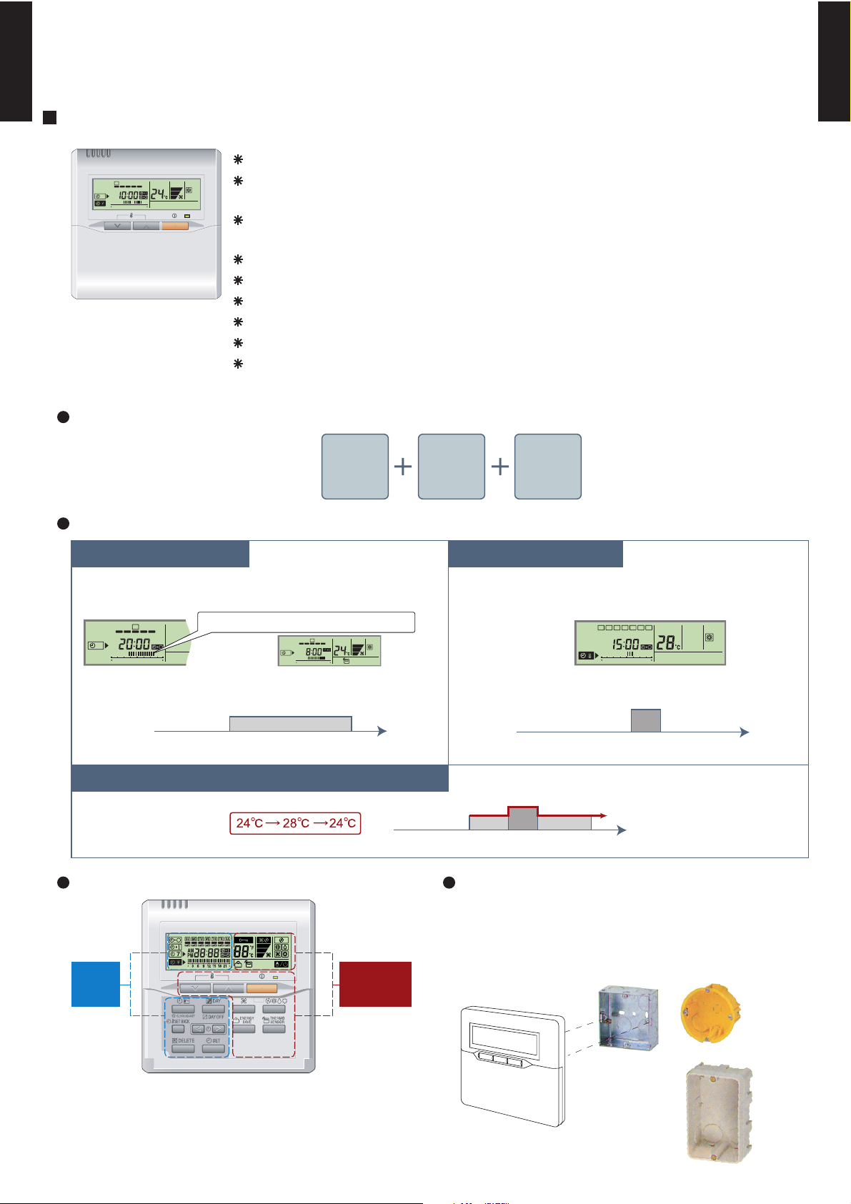
WIRED REMOTE CONTROLLER (FOR DUCT TYPE MODEL)
High performance and compact size
Built-in timers
Easy-to-understand operation Simple installation
FEATURES
Equipped with weekly timer as standard function.
(2 times Start / Stop per day for a week)
Various timer setup (ON / OFF / WEEKLY) are possible.
When setting up a timer, operation mode and a temperature
setup can be changed.
When a failure occurs,the error code is displayed. (Maximum of 16)
Error indication.(A maximum of 16 error histories are memorizable.)
Up to 16 indoor units can be simultaneously controlled.
Anti freeze and energy saving operation are possible.
Easy installation with a slim shape with no bulge in the back.
The room temperature can be controlled by being detected the temperature
accurately with built-in thermo sensor.
SU
MO
TU
WE
TH FR SA
7
3
12
6 9
15 18 21
European
switch box
JIS box
[
Variable timer control
]
Timer
area
Operation
area
0 3 6 9 12 15 18 21 Time
24°C
0 3 6 9 12 15 18 21 Time
28°C
SU
MO
TU
WE
TH FR SA
7
3
12
6 9
15 18 21
Easy-to-understand time bar display
Setup screen example
(Set to Wednesday: 8:00 to 20:00.)
Screen
after setup
SU
MO
TU
WE
TH FR SA
7
3
12
6 9
15 18 21
Setup screen example
(Set from Sunday to Saturday: 12:00 to 15:00, 28 °C.)
SU
MO
TU
WE
TH FR SA
3
12
6 9
15 18 21
The operation/display sections are zoned accord-
ing to time and operation, enabling variable pro-
gramming to match application.
Setback timerWeekly timer
At "Weekly timer" + "Set back timer" setup
Components are compatible with standard
switch boxes. Flat back construction allows
equipment to be installed wherever it is
needed.
Possible to set ON/OFF time to operate twice each day
of the week.
Possible to set temperature for two time spans and
for each day of the week.
24°C
0 3 6 9 12 15 18 21 Time
28°C
Wired
remote
controller
Weekly
timer
Setback
timer
Three functions are combined in
- (01 - 05) -
MULTI TYPE
2ROOM TYPE
MULTI TYPE
2ROOM TYPE
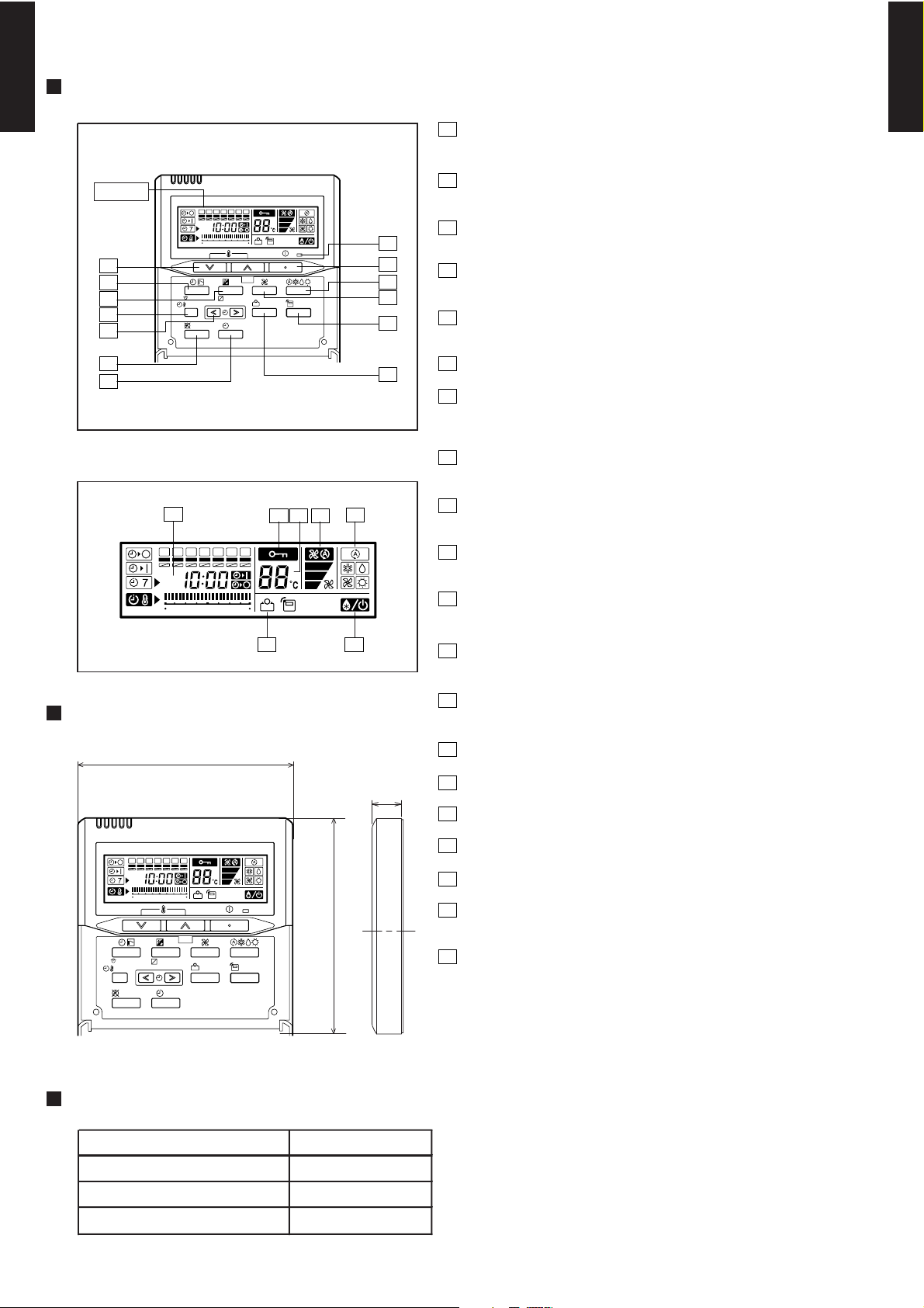
Display panel
FUNCTIONS
DIMENSION
SPECIFICATION
Display
13
12
11
10
9
2
1
3
5
6
4
7
8
DAY OFF
DELETE SET
ENERGY
SAVE
SET BACK
DAY
CLOCK ADJUST
SU
MO
TU
WE
TH FR
SA
369
12 15 18 21
THERMO
SENSOR
15
14
1617 18
1920
SU
MO
TU
WE
TH FR
SA
369
12 15 18 21
120
120
17
Front View
DAY OFF
DELETE SET
ENERGY
SAVE
SET BACK
DAY
CLOCK ADJUST
SU
MO
TU
WE
TH FR
SA
369
12 15 18 21
THERMO
SENSOR
[ Unit : mm ]
SIZE (H x W x D mm) 120 x 120 x 17
WEIGHT ( g ) 160
CABLE LENGTH ( m )
POWER ( V )
10
12
Set temperature button
7
6
1
START/STOP button
Pressed to start and stop operation.
17
Operation mode display
13
Operation lamp
Lights during operation and when the timer is on.
5
Energy save button
Turns the energy efficient mode on and off.
8
Day (DAY OFF) button
14
Timer and clock display
12
Set button
Sets the date, hour, minute and on-off time.
9
Set back button
Central control display
10
Timer mode (CLOCK ADJUST) button
Thermo sensor
Set time button
Pressed to set time.
Master control button
Selects the operating mode(AUTO, HEAT, FAN, COOL, DRY).
4
3
Fan control button
Selects the fan speed (AUTO, LOW, MED, HIGH).
18
Temperature display
16
Fan speed display
15
20
Energy save display
19
Stand by display
Indicates during defrosting operation.
Temporarily cancels of one day timer.
2
11
Delete button
Selects the setting temperature.
Selects the timer mode (OFF TIMER, ON TIMER, WEEKLY TIMER)
Pressed select the set back timer.
The schedule of a weekly timer is deleted.
Set the current time.
- (01 - 06) -
MULTI TYPE
2ROOM TYPE
MULTI TYPE
2ROOM TYPE
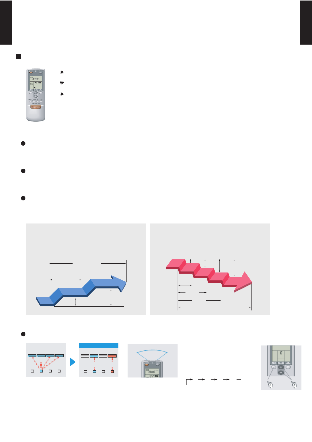
2-2.
WIRELESS REMOTE CONTROLLER
Built-in timers
Easy operation
FEATURES
Four kinds of timers. Easy operation.
Four kinds of timer setup (ON / OFF / PROGRAM / SLEEP) are possible.
Easy to change transmission code (4 patterns) by button operation.
Select from four different timer programs (On/Off/Program/Sleep).
Program timer
The program timer operates the ON and OFF timer once within a 24 hour period.
Sleep timer
The sleep timer function automatically corrects the temperature thermostat setting according to
the time setting to prevent excessive cooling and heating while sleeping.
Cooling operation/dry operation
60min.
1 °C
2 °C
When the sleep timer is set, the set temperature
automatically rises 1 °C every hour. The set
temperature can rise up to a maximum of 2 °C.
Heating operation
When the sleep timer is set, the set temperature
automatically drops 1 °C every 30 minutes. The
set temperature can drop to a maximum of 4 °C.
1 °C
30min.
60min.
90min.
2 °C
3 °C
4 °C
Timer setting
Timer setting
• Code selector switch eliminates unit
being wrongly switched.
(Up to 4 codes can be set.)
A B C D
A B
C
D
Mixed-up
After code change
•Wide and precise
transmitting range.
A B C D
1. Press the MASTER CONTROL
button for more than five seconds
to start the code change.
3. Press the MASTER CONTROL
button again to end the code
change.
2. Press the (+) or (-) button to
select the desired code.
2-2-1.
CASSETTE, UNIVERSAL AND WALL MOUNTED TYPE MODEL
- (01 - 07) -
MULTI TYPE
2ROOM TYPE
MULTI TYPE
2ROOM TYPE
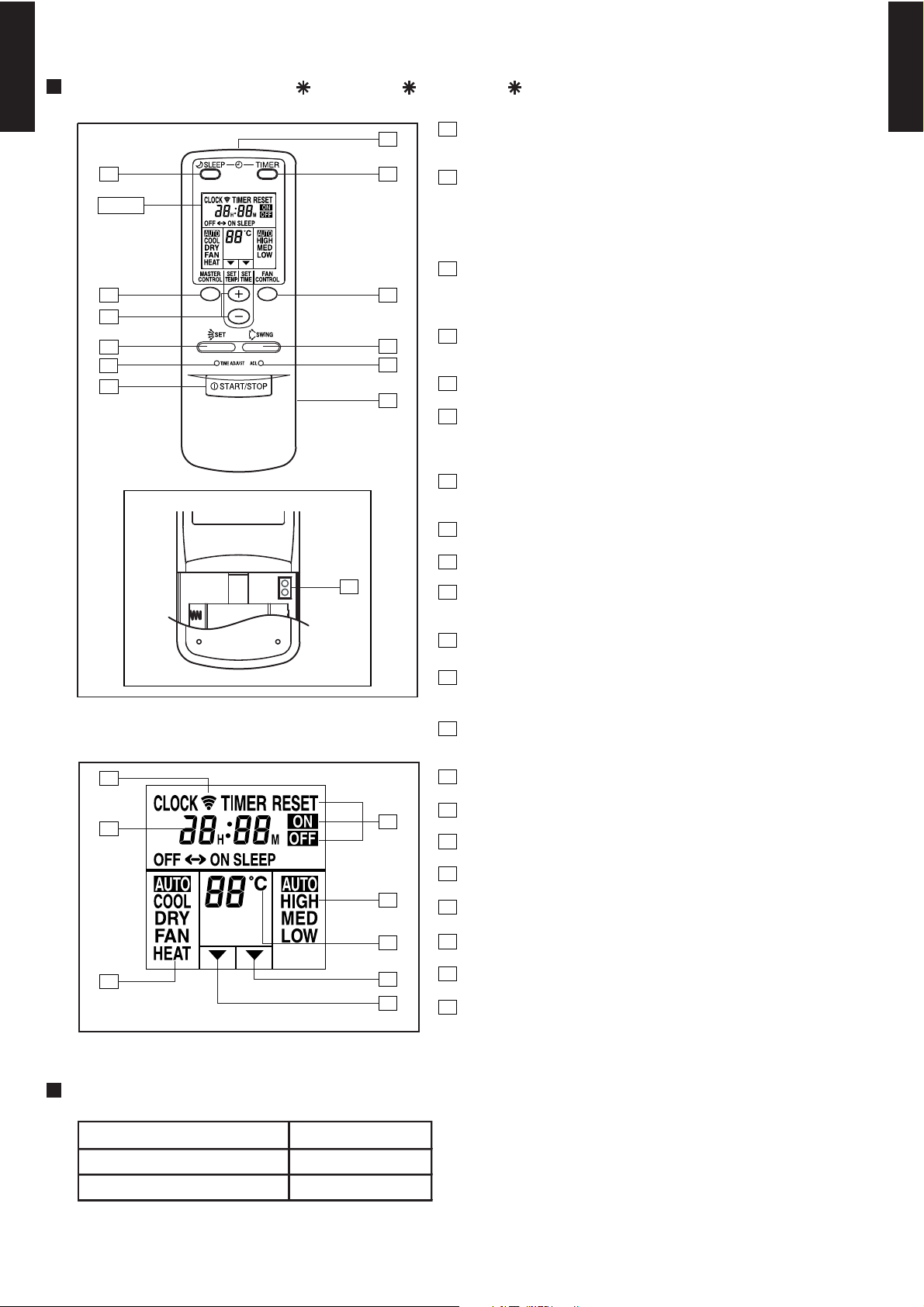
Display panel
Display
64
1
8
7
9
3
2
5
12
13
10
14
15
16
17
20
19
18
21
1
START/STOP button
Pressed to start and stop operation
Time adjust button
Sets the current time.
2
3
4
Sleep timer button
Pressed to select sleep timer.
5
Signal transmitter
6
Timer button
Pressed to select the timer mode. (OFF TIMER, ON TIMER,
PROGRAM TIMER, TIMER RESET)
7
Fan control button
8
Battery compartment lid
9
Air flow direction set button
17
18
Clock display
21
Master control display
20
Set temperature display
Fan speed display
12
Timer set indicator
Temperature set indicator
19
Timer mode display
Set temp./Set time/
Set remote controller custom code buttons
Sets the indoor temp./ Sets the current time and on-off time.
/Sets R.C. custom code.
Master control / Code change buttons
Selects the operating mode (AUTO, HEAT, FAN, COOL, DRY).
/Start / end R.C. custom code change. (Max 4 types)
Selects the fan speed (AUTO, LOW, MED, HIGH).
10
11
14
ACL button
Air flow direction swing button
Used when replacing batteries or change the code.
15
16
Transmit indicator
TEST
RUN
11
13
Test run button
Used when testing the air conditioner after installation.
FUNCTIONS (For AU 12L, AU 14L, AU 18L)
SPECIFICATION
SIZE (H x W x D mm) 158 x 56 x 20
WEIGHT ( g ) 70
ACCESSORY Holder
- (01 - 08) -
MULTI TYPE
2ROOM TYPE
MULTI TYPE
2ROOM TYPE
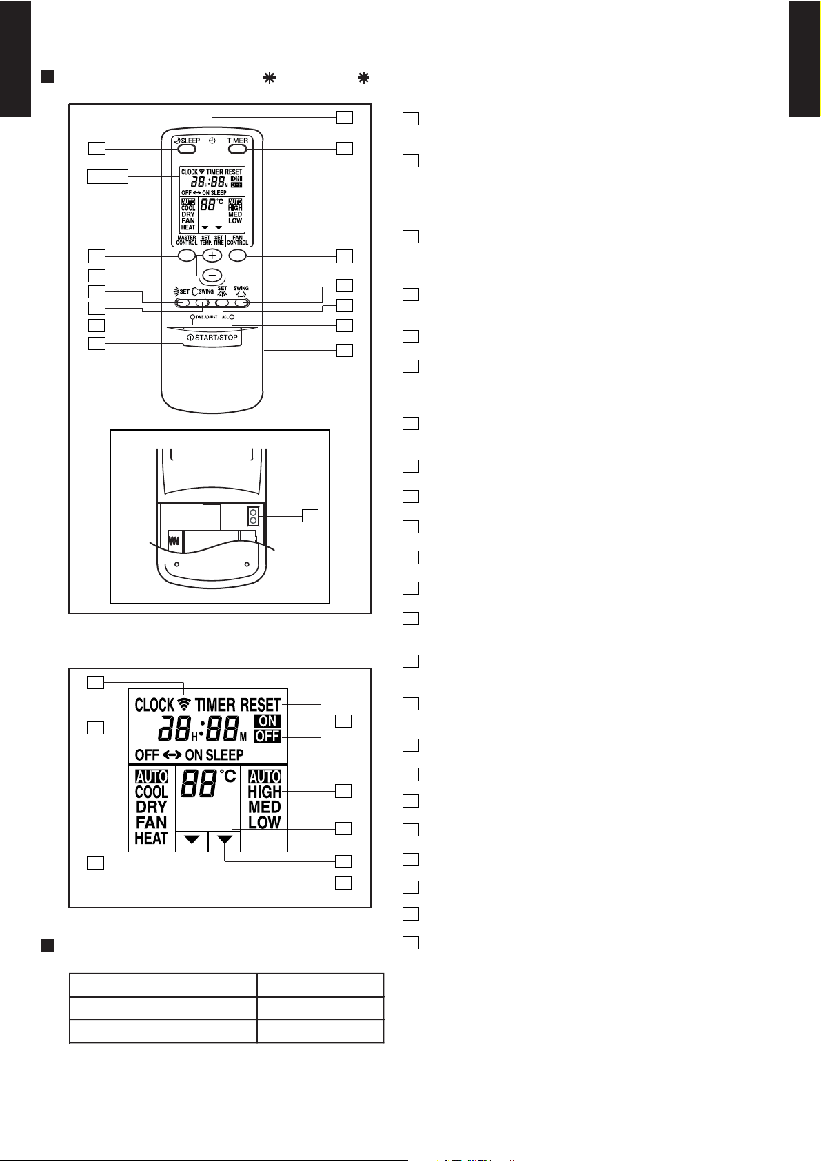
Display panel
SPECIFICATION
Display
64
1
8
7
10
9
12
11
3
2
5
15
13
14
TEST
RUN
16
17
18
19
22
21
20
23
SIZE (H x W x D mm) 158 x 56 x 20
WEIGHT ( g ) 70
ACCESSORY Holder
1
START/STOP button
Pressed to start and stop operation
Time adjust button
Sets the current time.
2
3
4
Sleep timer button
Pressed to select sleep timer.
5
Signal transmitter
6
Timer button
Pressed to select the timer mode. (OFF TIMER, ON TIMER,
PROGRAM TIMER, TIMER RESET)
7
Fan control button
8
Battery compartment lid
9
Air flow direction vertical set button
10
Air flow direction vertical swing button
11
Air flow direction horizontal swing button
12
Air flow direction horizontal set button
19
20
Clock display
23
Master control display
22
Set temperature display
Fan speed display
15
Timer set indicator
Temperature set indicator
21
Timer mode display
Set temp./Set time buttons/Set remote controller
custom code buttons
Sets the indoor temp./Sets the current time and on-off time
/Set R.C. custom code
Master control button/
Code change
Selects the operating mode (AUTO, HEAT, FAN, COOL, DRY).
Start/end R.C. custom code change. (Max. 4 types)
Selects the fan speed (AUTO, LOW, MED, HIGH).
13
14
16
Test run button
Used when testing the air conditioner after installation.
ACL button
Used when replacing batteries or change the code.
17
18
Transmit indicator
FUNCTIONS (For AB 14L, AB 18L)

- (01 - 09) -
MULTI TYPE
2ROOM TYPE
MULTI TYPE
2ROOM TYPE
Display panel
Display
64
1
8
7
9
3
2
5
12
13
10
14
15
16
17
20
19
18
21
1
START/STOP button
Pressed to start and stop operation
Time adjust button
Sets the current time.
2
3
4
Sleep timer button
Pressed to select sleep timer.
5
Signal transmitter
6
Timer button
Pressed to select the timer mode. (OFF TIMER, ON TIMER,
PROGRAM TIMER, TIMER RESET)
7
Fan control button
8
Battery compartment lid
9
Air flow direction set button
17
18
Clock display
21
Master control display
20
Set temperature display
Fan speed display
12
Timer set indicator
Temperature set indicator
19
Timer mode display
Set temp./Set time/
Set remote controller custom code buttons
Sets the indoor temp./ Sets the current time and on-off time.
/Sets R.C. custom code.
Master control / Code change buttons
Selects the operating mode (AUTO, HEAT, FAN, COOL, DRY).
/Start / end R.C. custom code change. (Max 4 types)
Selects the fan speed (AUTO, QUIET, LOW, MED, HIGH).
10
11
14
ACL button
Air flow direction swing button
Used when replacing batteries or change the code.
15
16
Transmit indicator
TEST
RUN
11
13
Test run button
Used when testing the air conditioner after installation.
SPECIFICATION
SIZE (H x W x D mm) 158 x 56 x 20
WEIGHT ( g ) 70
ACCESSORY Holder
QUIET
QUIET
FUNCTIONS (For AS 7L, AS 9L, AS 12L)

- (01 - 10) -
MULTI TYPE
2ROOM TYPE
MULTI TYPE
2ROOM TYPE
Display panel
SPECIFICATION
Display
64
1
8
7
10
9
12
11
3
2
5
15
13
14
TEST
RUN
16
17
18
19
22
21
20
23
SIZE (H x W x D mm) 158 x 56 x 20
WEIGHT ( g ) 70
ACCESSORY Holder
1
START/STOP button
Pressed to start and stop operation
Time adjust button
Sets the current time.
2
3
4
Sleep timer button
Pressed to select sleep timer.
5
Signal transmitter
6
Timer button
Pressed to select the timer mode. (OFF TIMER, ON TIMER,
PROGRAM TIMER, TIMER RESET)
7
Fan control button
8
Battery compartment lid
9
Air flow direction vertical set button
10
Air flow direction vertical swing button
11
Air flow direction horizontal swing button
12
Air flow direction horizontal set button
19
20
Clock display
23
Master control display
22
Set temperature display
Fan speed display
15
Timer set indicator
Temperature set indicator
21
Timer mode display
Set temp./Set time buttons/Set remote controller
custom code buttons
Sets the indoor temp./Sets the current time and on-off time
/Set R.C. custom code
Master control button/
Code change
Selects the operating mode (AUTO, HEAT, FAN, COOL, DRY).
Start/end R.C. custom code change. (Max. 4 types)
Selects the fan speed (AUTO, QUIET, LOW, MED, HIGH).
13
14
16
Test run button
Used when testing the air conditioner after installation.
ACL button
Used when replacing batteries or change the code.
17
18
Transmit indicator
QUIET
QUIET
FUNCTIONS (For AS 18L)

- (01 - 11) -
MULTI TYPE
2ROOM TYPE
MULTI TYPE
2ROOM TYPE
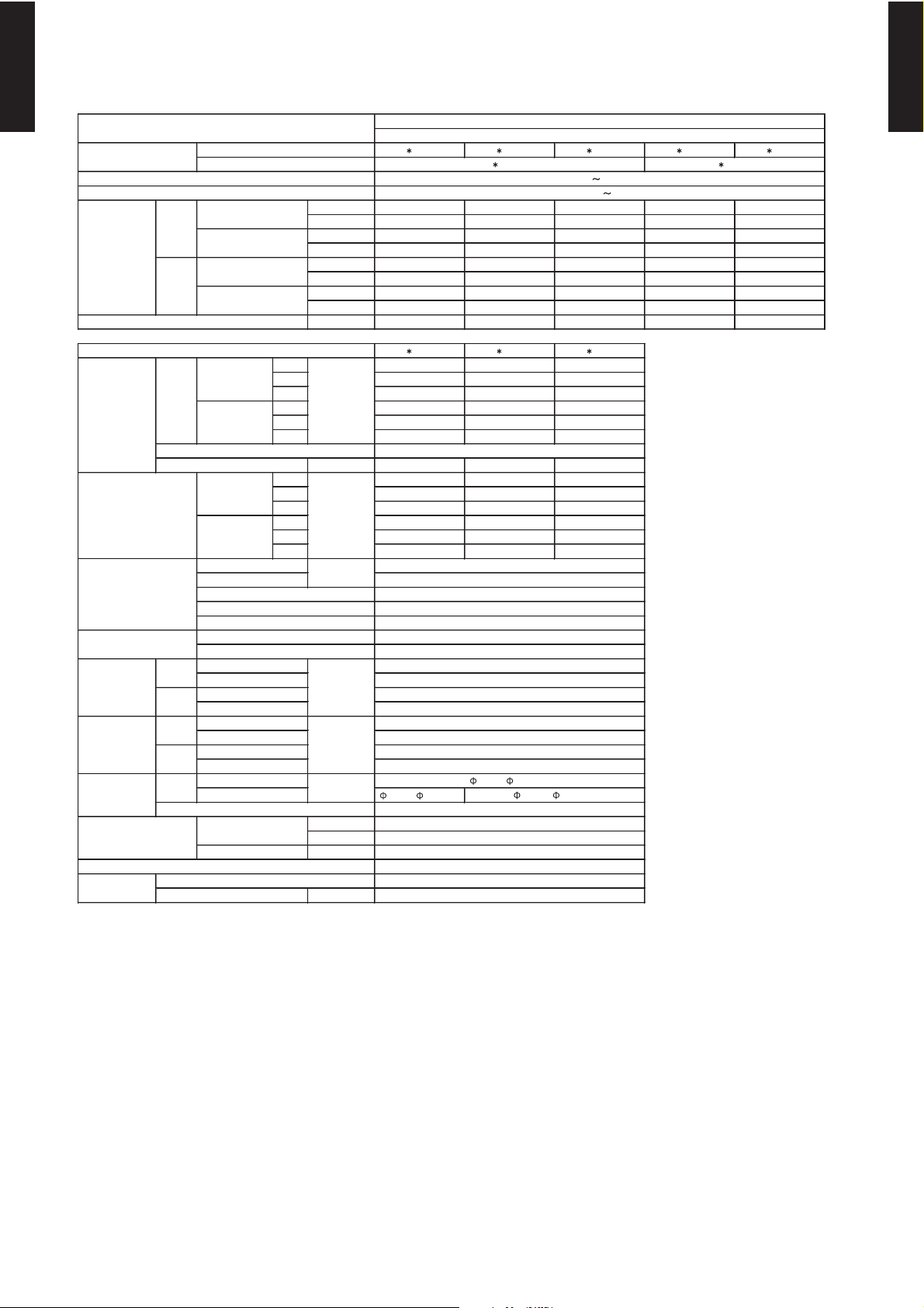
3. SPECIFICATIONS
3-1. DUCTED MODEL
AR 9LUAB AR 12LUAD AR 14 LUAD AR 18 LUAD AR 9LUAB AR 12LUAD AR 14 LUAD
kW 2.6 3.5 4.3 5.4 2.6 3.5 4.3
BTU/h 890 0 119 00 147 00 184 00 89 00 11 900 14 700
kW 1.8 - 2.8 1.8 - 3.9 1.8 - 4.9 2.0 - 6.0 1.8 - 2.8 1.8 - 3.9 1.8 - 4.9
BTU/h 610 0 - 96 00 61 00 - 1 3300 61 00 - 1 6700 68 00 - 2 0500 6 100 - 9600 610 0 - 13 300 610 0 - 16 700
kW 3.1 4.0 4.9 6.0 3.1 4.0 4.9
BTU/h 1 0900 1 3700 1 6700 2 0500 1 0900 1 3700 1 6700
kW 1.8 - 3.8 1.8 - 4.6 1.8 - 6.0 2.0 - 7.5 1.8 - 3.8 1.8 - 4.6 1.8 - 6.0
BTU/h 610 0 - 130 00 6100 - 1570 0 610 0 - 20 500 6 800 - 2560 0 61 00 - 13 000 610 0 - 157 00 6 100 - 2050 0
l/h (pints /h) 1.0 ( 2.1 ) 1.2 ( 2.5 ) 1.5 ( 3.2 ) 1.7 ( 3.6 ) 1.0 ( 2.1 ) 1.2 ( 2.5 ) 1.5 ( 3.2 )
AR 9LUAB AR 12LUAD AR 14 LUAD AR 18 LUAD
High 450 600 800 800
Med 41 0 500 620 640
Low 3 70 43 0 480 500
High 450 580 780 800
Med 41 0 500 620 640
Low 3 70 43 0 480 500
Type × Q'ty Siroc co × 1
Motor o utput W 13
Re comm end ed s tatic p ress ure Pa
High 39 33 40 41
Med 37 30 35 35
Low 3 4 27 3 0 3 0
High 39 33 40 41
Med 37 30 35 35
Low 3 4 27 3 0 3 0
294 × 410 × 26. 6 294 × 700 × 39. 9
Fin p ic h
Rows x Sta ges 3 × 14
Pipe type
Fin typ e
Mate ria l
Colou r
Net 217 × 663 × 595
Gros s 324 × 785 × 686
Net 18 ( 40 )
Gros s 22 ( 48 )
Liquid
Ga s
Metho d
°C
%RH
Hea ting °C
mm
Note :
Sp ecification s a re ba se d on the fo llowing cond ition s.
Coo ling : Indoo r temp eratu re of 2 7 °CDB / 1 9 °CWB.a nd o utdoo r temp eratu re of 3 5 °CDB/24 °CWB.
Hea ting : Ind oor te mpera ture of 20 °C DB / 15 °C WB.an d outd oor te mpera ture of 7 °CDB/6 °CWB.
Sta nda rd sta tic pre ss ure : 0Pa
Pipe leng th : 7. 5 m, He ight differe nce : 0 m. (Outdoo r unit - Indo or unit)
Cop per
Oute r diam eter: 26.0 / Inne r diam ete r: 21.5
ABS
Wired
16 to 30
80 or les s
18 to 32
Flare
9.5 2 ( 3/8 in.)
12. 70 ( 1/2 in.)
Siroc co × 2
42
0 to 40
2 × 14
1.3
294 × 700 × 26.6
Po wer s ource
Available voltage ran ge
Mode l n ame
m
3
/h
mm
Ra ted
Min-Max
Ra ted
Min-Max
Dimen sions (H × W × D)
Mode l n ame
Coo ling
Hea ting
dB(A)
Coo ling
Hea ting
Airflow
rate
Ca pac ity
Coo ling
Hea ting
Moisture rem oval
Hea t exc han ger typ e
Enc lo sure
So und p ress ure le vel
Fa n
We igh t
Dimen sions
( H × W × D )
Re mote contro ller type
Drain pipe
Mate ria l
Size
Ope ration rang e
Coo ling
Con nec tio n pipe
Size
mm
29 ( 64 )
kg(lb.)
mm
217 × 953 × 595
6.3 5 ( 1/ 4 in.)
230 V 50 Hz
198 -264V 50 Hz
AO 18 LMAK2
AO 24 LMAM2
324 × 107 5 × 68 6
25 ( 55 )
Aluminium
Ga lva nized ste el sh eet
-
INDOOR UNIT
OUTDOO R UNIT
MULTI S ATTELITE SYSTE M MODE L
INVERTER HEATPUMP
TYPE
- (01 - 12) -
MULTI TYPE
2ROOM TYPE
MULTI TYPE
2ROOM TYPE
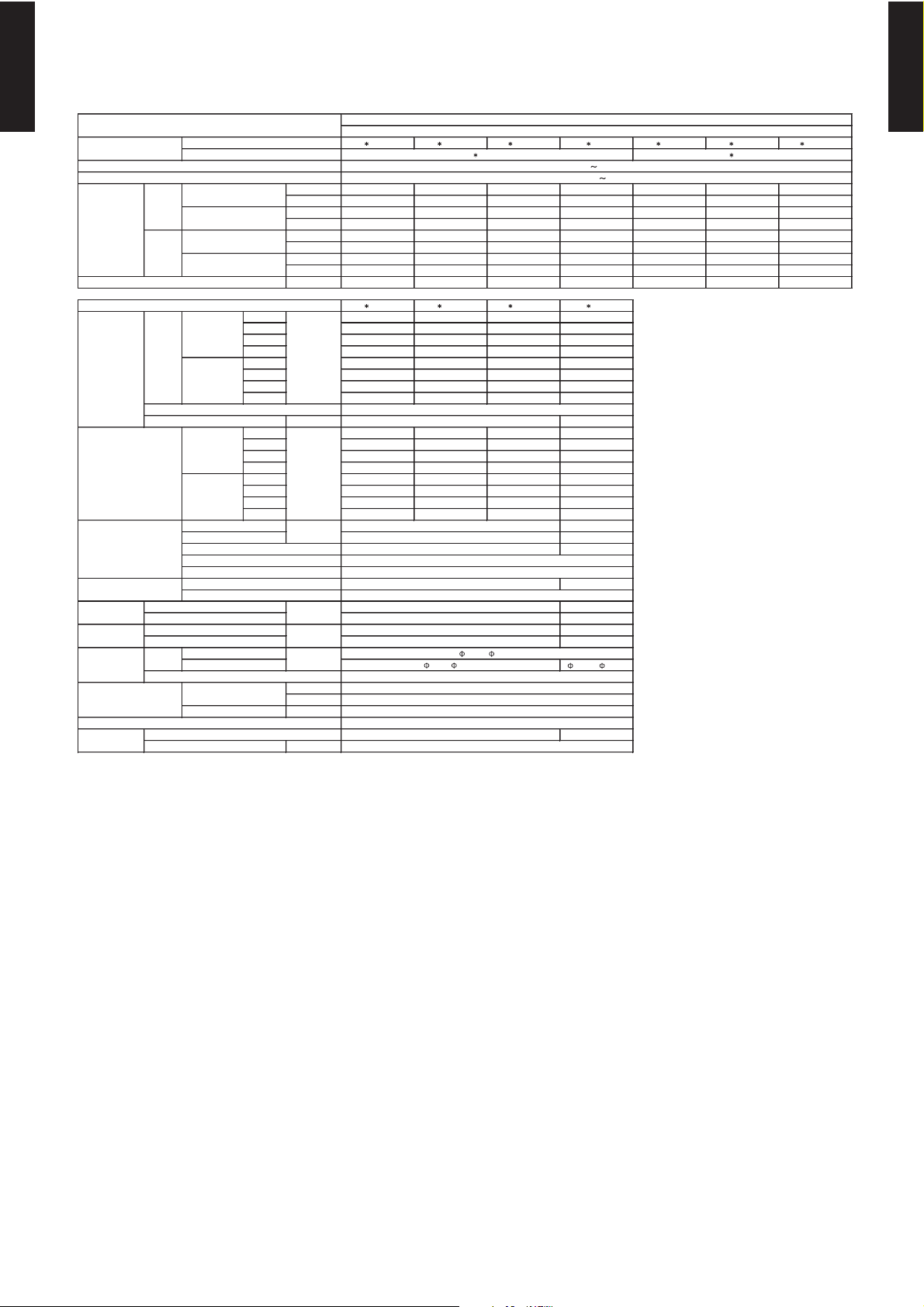
3-2. CASSETTE MODEL
AU 12LBAB AU 14LBAB AU 18LBAB AU 12LBAB AU 14LBAB
kW 3.3 4.0 4.5 3.3 4.0
BTU/h 11300 13700 15400 11300 13700
kW 1.8 - 3.7 1.8 - 4.5 2.0 - 4.7 1.8 - 3.7 1.8 - 4.5
BTU/h 6100 - 12600 6100 - 15400 6800 - 16000 6100 - 12600 6100 - 15400
kW 3.7 4.3 5.5 3.7 4.3
BTU/h 12600 14700 18800 12600 14700
kW 1.8 - 4.4 1.8 - 5.3 2.0 - 6.0 1.8 - 4.4 1.8 - 5.3
BTU/h 6100 - 15000 6100 - 18100 6800 - 20500 6100 - 15000 6100 - 18100
l/h (pints/h) 1.3 ( 2.7 ) 1.5 ( 3.2 ) 2.0 ( 4.3 ) 1.3 ( 2.7 ) 1.5 ( 3.2 )
AU 12LBAB AU 14LBAB AU 18LBAB
High 550 550 620
Med 500 500 520
Low 440 440 450
High 550 550 620
Med 500 500 520
Low 440 440 450
Type × Q'ty
Motor output W 10 10 14
High 42 42 44
Med 39 39 41
Low 36 36 38
High 42 42 44
Med 39 39 41
Low 36 36 38
Fin pich
Rows x Stages
Pipe type
Fin type
Material
Colour
Unit
Panel
Unit
Panel
Unit
Panel
Unit
Panel
Liquid
Gas 9.52 ( 3 / 8 in.)
Method
°C
%RH
Heating °C
mm
Note :
Specifications are based on the following conditions.
Cooling : Indoor temperature of 27 °CDB / 19 °CW B.and outdoor temperature of 35 °CDB/24 °CWB.
Heating : Indoor temperature of 20 °CDB / 15 °CW B.and outdoor temperature of 7 °CDB/6 °CWB.
Pipe length : 7.5 m, Height difference : 0 m.(Outdoor unit - Indoor unit)
70 × 720 × 720
MULTI SATTELITE SYSTEM MODEL
INVERTER HEATPUMP
AO 24LMAM2
AO 18LMAK2
35 × 650 × 650
Aluminium
2 × 10
Copper
198-264V 50Hz
Flare
kg(lb.)
mm
mm
12.70 ( 1 / 2 in.)
18 ( 40 )
2.2 ( 4.9 )
6.35 ( 1 / 4 in.)
280 × 710 × 750
23 ( 51 )
4.3 ( 9.6 )
Moisture removal
Cooling
Model name
ABS
White(5Y9/0.5NN)
235 × 580 × 580
Enclosure(Panel)
Sound pressure level
TYPE
Power source
Model name
Available voltage range
INDOOR UNIT
OUTDOOR UNIT
m
3
/h
Fan
Airflow
rate
Capacity
Cooling
Heating
Rated
Min-Max
Rated
Min-Max
dB(A)
mm
Cooling
Heating
Dimensions (H × W × D)
Connection pipe
Size
Heat exchanger type
Heating
Dimensions
( H × W × D )
Net
Gross
Weight
Net
Gross
Operation range
Remote controller type
Drain pipe
Material
Size
Cooling
PP
Outer diameter: 37.0 / Inner diameter: 32.0
18 to 32
80 or less
16 to 30
Wireless
Turbo × 1
210 × 1000 × 26.6
1.4
230V 50Hz
- (01 - 13) -
MULTI TYPE
2ROOM TYPE
MULTI TYPE
2ROOM TYPE
3-3. CEILING MODEL
AB 14LBAJ AB 18LBAJ AB 14LBAJ
AO 18LMAK2
kW 4.2 5.0 4.2
BTU/h 14300 17100 14300
kW 1.8 - 4.9 2.0 - 5.7 1.8 - 4.9
BTU/h 6100 - 16700 6800 - 19500 6100 - 16700
kW 4.8 6.1 4.8
BTU/h 16400 20800 16400
kW 1.8 - 6.0 2.0 - 7.4 1.8 - 6.0
BTU/h 6100 - 20500 6800 - 25300 6100 - 20500
l/h (pints/h) 1.5 ( 3.2 ) 1.7 ( 3.6 ) 1.5 ( 3.2 )
AB 14LBAJ AB 18LBAJ
High 640 780
Med 560 650
Low 480 550
High 640 780
Med 560 650
Low 480 550
Type × Q'ty
Motor output W 16 30
High 37(Floor console) ,36 (Under ceiling) 44(Floor console) , 43(Under ceiling)
Med 34(Floor console) ,33 (Under ceiling) 41(Floor console) , 40(Under ceiling)
Low 30(Floor console) , 29(Under ceiling) 36(Floor console) , 35(Under ceiling)
High 37(Floor console) , 36(Under ceiling) 44(Floor console) , 43(Under ceiling)
Med 34(Floor console) , 33(Under ceiling) 41(Floor console) , 40(Under ceiling)
Low 30(Floor console) , 29(Under ceiling) 36(Floor console) ,35 (Under ceiling)
294 × 800 × 26.6 294 × 700 × 39.9
Fin pich 1.2 1.3
Rows x Stages 2 × 12 3 × 12
Pipe type
Material
Colour
Net
Gross
Net
Gross
Liquid
Gas
Method
°C
%RH
Heating °C
mm
Note :
Specifications are based on the following conditions.
Cooling : Indoor temperature of 27 °CDB / 19 °CW B.and outdoor temperature of 35 °CDB/24 °CWB.
Heating : Indoor temperature of 20 °CDB / 15 °CW B.and outdoor temperature of 7 °CDB/6 °CWB.
Pipe length : 7.5 m, Height difference : 0 m.(Outd oor unit - Indoor unit)
Dimensions (H × W × D)
INDOOR UNIT
OUTDOOR UNIT
Fin type
Drain pipe
Material
Size
Operation range
Cooling
Heating
Remote controller type
kg(lb.)
Connection pipe
Size
mm
Weight
Model name
Available voltage range
Dimensions
(H × W × D)
mm
Airflow
rate
Heat exchanger type
Enclosure
Sound pressure level
Cooling
Heating
Min-Max
Moisture removal
Cooling
m
3
/h
Fan
Model name
Capacity
Cooling
Heating
Sirocco × 2
Copper
Aluminium
mm
dB(A)
ABS
White(5Y9/0.5NN)
199 × 990 × 655
320 × 1150 × 790
28 ( 62 )
37 ( 82 )
6.35 ( 1/4 in.)
12.70 ( 1/2 in.)
Wireless
Outer diameter: 29.0 / Inner diameter: 25.0
PVC
Flare
18 to32
80 or less
16 to 30
Rated
Min-Max
Rated
MULTI SATTELITE SYSTEM MODEL
INVERTER HEATPUMP
230V 50Hz
198-264V 50Hz
AO 24LMAM2
TYPE
Power source
- (01 - 14) -
MULTI TYPE
2ROOM TYPE
MULTI TYPE
2ROOM TYPE
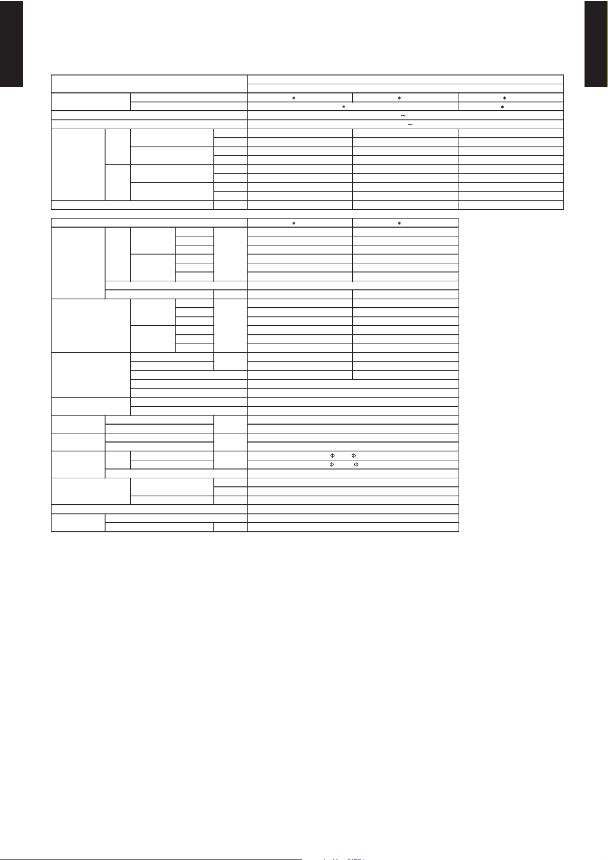
3-4. WALL MOUNTED MODEL
AS 7LMACW AS 9LMACW AS 12LMACW AS 18LBAJ AS 7LMACW AS 9LMACW AS 12LMACW
kW 2.2 2.7 3.5 5.2 2.2 2.7 3.5
BTU/h 7500 9200 11900 17800 7500 9200 11900
kW 1.8 - 2.5 1.8 - 3.0 1.8 - 3.7 2.0 - 5.9 1.8 - 2.5 1.8 - 3.0 1.8 - 3.7
BTU/h 6100 - 8500 6100 - 10200 6100 - 12600 6800 - 20100 6100 - 8500 610 0 - 10200 6100 - 12600
kW 2.6 3.2 4.0 6.0 2.6 3.2 4.0
BTU/h 8900 10900 13700 20500 8900 10900 13700
kW 1.8 - 3.2 1.8 - 3.9 1.8 - 4.4 2.0 - 7.4 1.8 - 3.2 1.8 - 3.9 1.8 - 4.4
BTU/h 6100 - 10900 6100 - 13300 6100 - 15000 6800 - 25300 6100 - 10900 6100 - 13300 6100 - 15000
l/h (pints/h) 0.8 ( 1.7 ) 1.0 ( 2.1 ) 1.2 ( 2.5 ) 1. 7 ( 3.6 ) 0.8 ( 1.7 ) 1.0 ( 2.1 ) 1 .2 ( 2.5 )
AS 7LMACW AS 9LMACW AS 12LMACW AS 18LBAJ
High 430 470 520 950
Med 400 430 470 800
Low 38 0 380 420 670
Quiet 350 350 380 570
High 430 470 520 950
Med 400 430 470 800
Low 38 0 380 420 670
Quiet 350 350 380 570
Type × Q'ty
Motor output W 38
High 34 36 38 43
Med 32 34 37 39
Low 31 31 35 35
Quiet 2 9 29 33 32
High 34 35 38 43
Med 32 33 35 39
Low 30 30 31 35
Quiet 2 8 28 29 32
Dimensions (H × W × D) 336 × 855 × 26.6
Fin pich 1.2
2 × 16
Material ABS
Colour
Net 320 × 1120 ×
220
Gross 348 × 1240 × 427
Net 16 ( 35 )
Gross 22 ( 48 )
Liquid
Gas 12.70 ( 1/2in.)
Method
°C
%RH
Heating °C
PVC
mm
Note :
Specifications are based on the following conditions.
Cooling : Indoor temperature of 27 °CDB / 19 °CW B.and outdoor temperature of 35 °CDB/24 °CWB.
Heating : Indoor temperature of 20 °CDB / 15 °CW B.and outdoor temperature of 7 °CDB/6 °CWB.
Pipe length : 7.5 m, Height difference : 0 m.(Outdoor unit - Indoor unit)
MULTI SATTELITE SYSTEM MODEL
INVERTER HEATPUMP
HIPS
Cross flow fan × 1
16.5
252 × 632 × 26.6
1.3
Aluminium
AO 18L MAK2
AO 24L MAM2
Operation range
Cooling
kg(lb.)
Connection pipe
Size
mm
Weight
Remote controller type
Drain pipe
Material
Size
Dimensions
( H×W ×D )
Airflow
rate
Heat exchanger type
Enclosure
Sound pressure level
Fin type
Cooling
Rated
Min-Max
Rated
dB(A)
Moisture removal
Rows x Stages
Min-Max
Cooling
TYPE
Cooling
m
3
/h
Fan
Power source
Available voltage range
Capacity
INDOOR UNIT
OUTDOOR UNIT
Flare
Soft PVC
9.52 ( 3 /8in.)
257 × 808 × 187
270 × 850 × 310
8 ( 18 )
16 to 30
Wireless
18 to 32
80 or less
Heating
mm
Model name
Copper
2 × 12
Pipe type
Heating
Outer diameter: 17.0 / Inner diameter: 12.0
Model name
230V 50Hz
198-264V 50Hz
Heating
White(5Y9/0.5NN)
6.35 ( 1 /4in.)
10 ( 22 )
mm
- (01 - 15) -
MULTI TYPE
2ROOM TYPE
MULTI TYPE
2ROOM TYPE
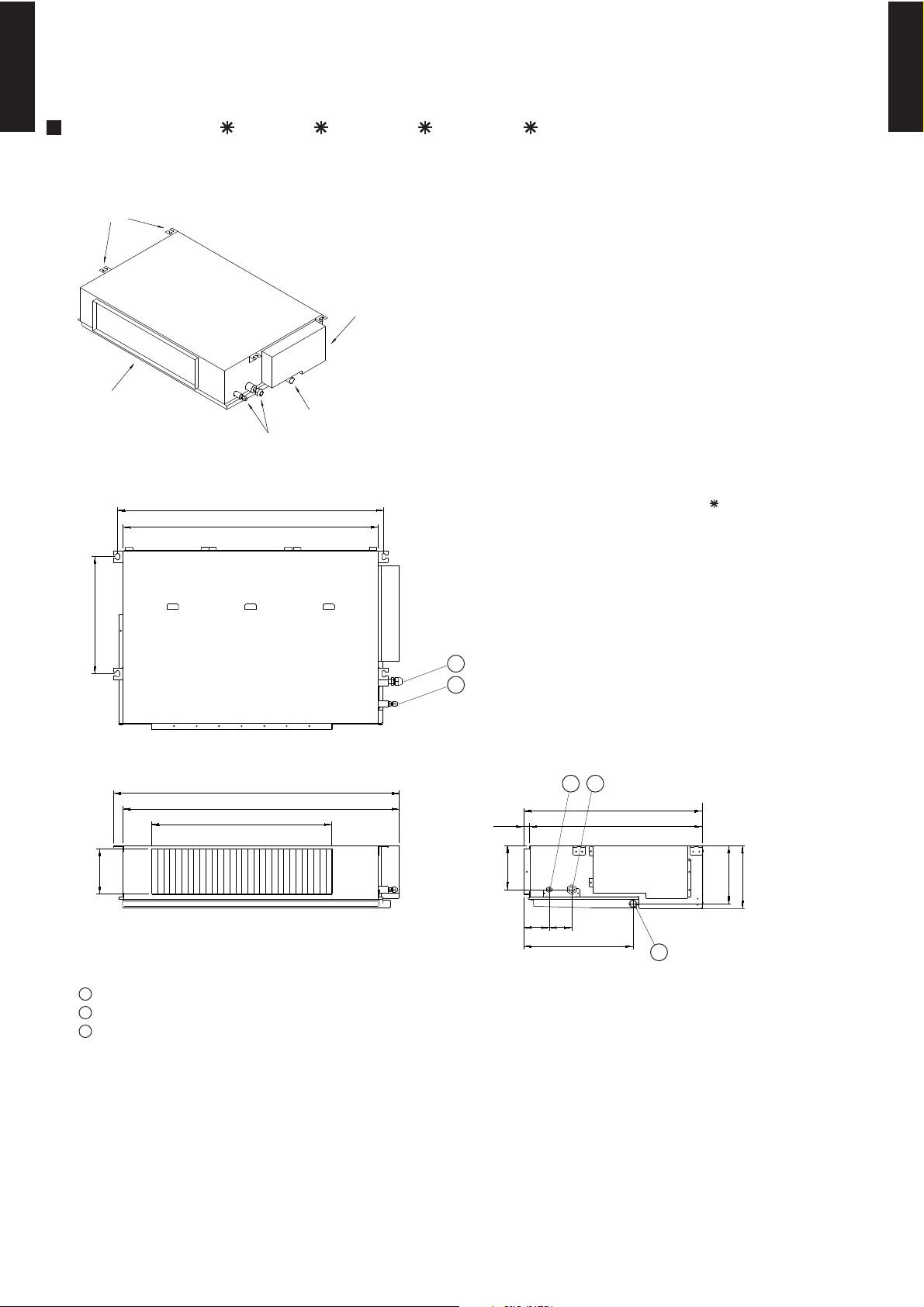
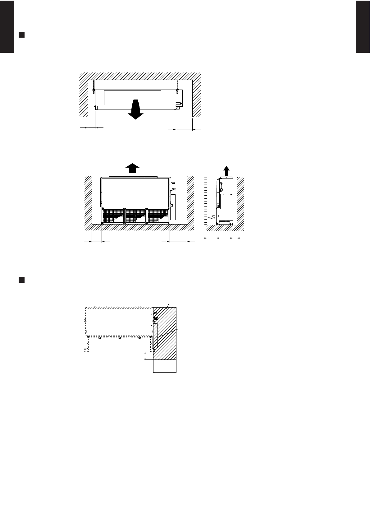
4-1. DUCTED MODEL
MODELS : AR 9L, AR 12L, AR 14L, AR 18L
(Unit : mm)
( ) : AR 9L
886(596)
953(663)
850(560)
920(630)
600(400)
150
150
595
57520
85 75
364
390
194
217
BRACKETS
AIR FLOW OUTLET
CONTROL BOX
COUPLING PIPE ASSY
DRAIN PORT
1
Refrigerant piping flare connection (Gas)
Refrigerant piping flare connection (Liquid)
Drain piping connection
2
3
12
3
1
2
Top view
Front view
Side view
4. DIMENSIONS
- (01 - 16) -
MULTI TYPE
2ROOM TYPE
MULTI TYPE
2ROOM TYPE
MOUNTING POSITION
MAINTENANCE HOLE
(Unit : mm)
Left
side
Right
side
100 or more
300 or more
Strong and durable ceiling
Indoor unit
Left
side
Right side
(PIPE side)
Strong and durable floor
100 or more 300 or more
30
or more
30
or more
Maintenance hole
Unit
100
or more
Control box
300
or more
- (01 - 17) -
MULTI TYPE
2ROOM TYPE
MULTI TYPE
2ROOM TYPE
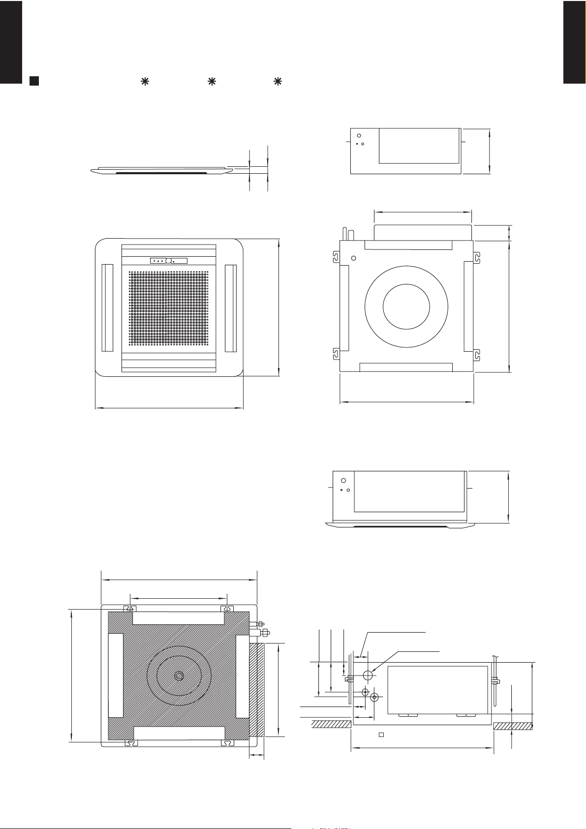
4-2. CASSETTE MODEL
(Unit : mm)
MODELS : AU 12L, AU 14L, AU 18L
20
35
66
235
650
245
580
650
580
440
(Hanging bolt position)
606
(Hanging bolt position)
400
(Grille measurement)
650
440
131
245
54
111
47
66
46
60
86
Drain pipe
600
(Ceiling opening measurement)
Side view
Top view
Bottom view
Bottom view (Panel)
- (01 - 18) -
MULTI TYPE
2ROOM TYPE
MULTI TYPE
2ROOM TYPE
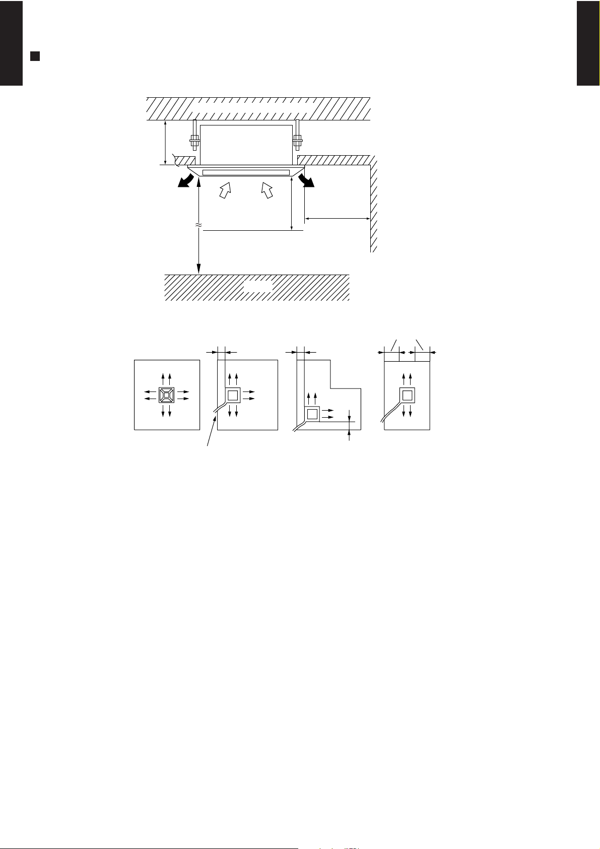
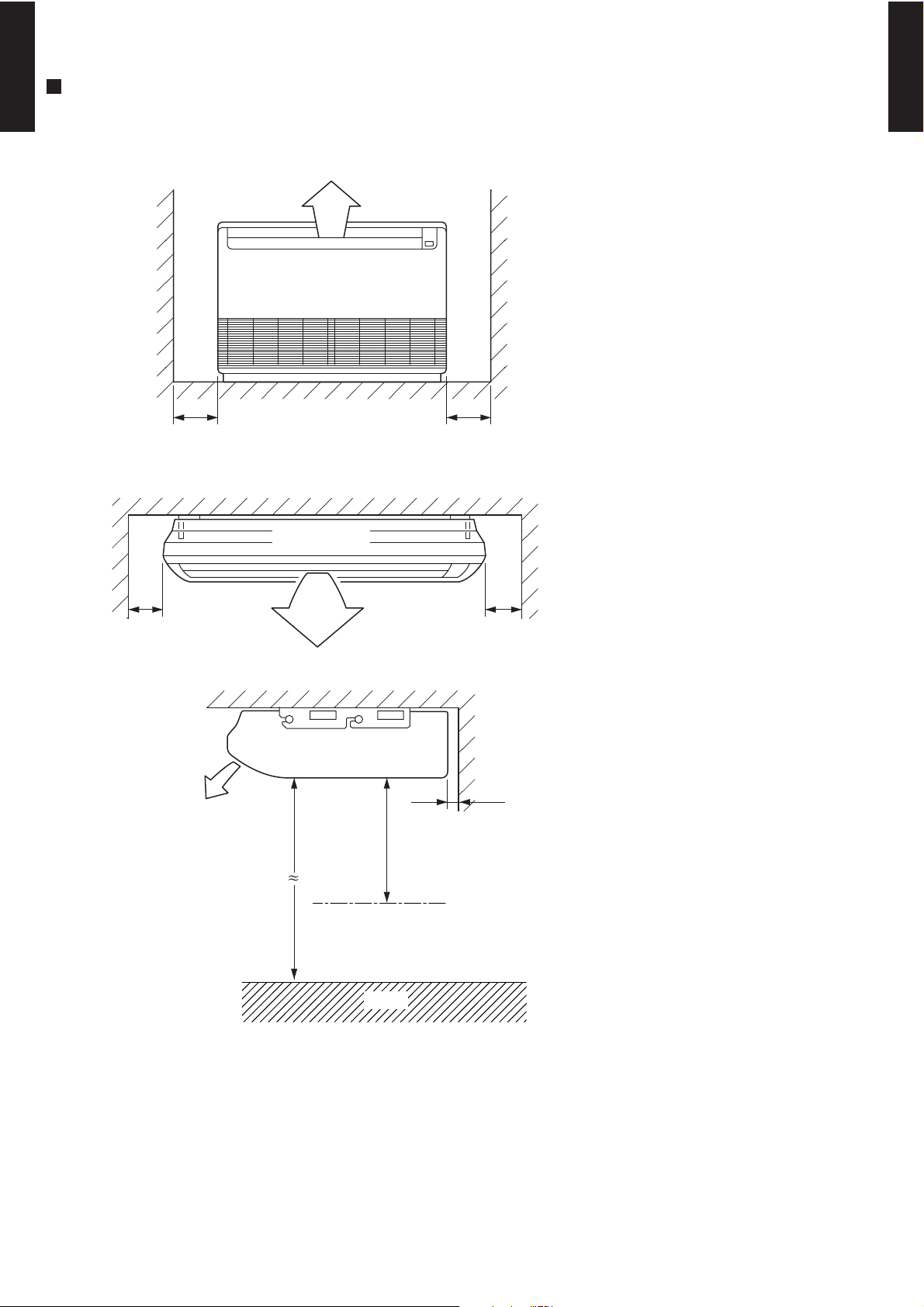
Strong and durable ceiling
250 or more
1,000 or more
Obstruction
1,000
or more
100 or more 100 or more
100 or more
100 or more
(4 directions) (3 directions)
Piping position
(2 directions) (2 directions)
MOUNTING POSITION
2,300
or more
Floor
(Unit : mm)
- (01 - 19) -
MULTI TYPE
2ROOM TYPE
MULTI TYPE
2ROOM TYPE
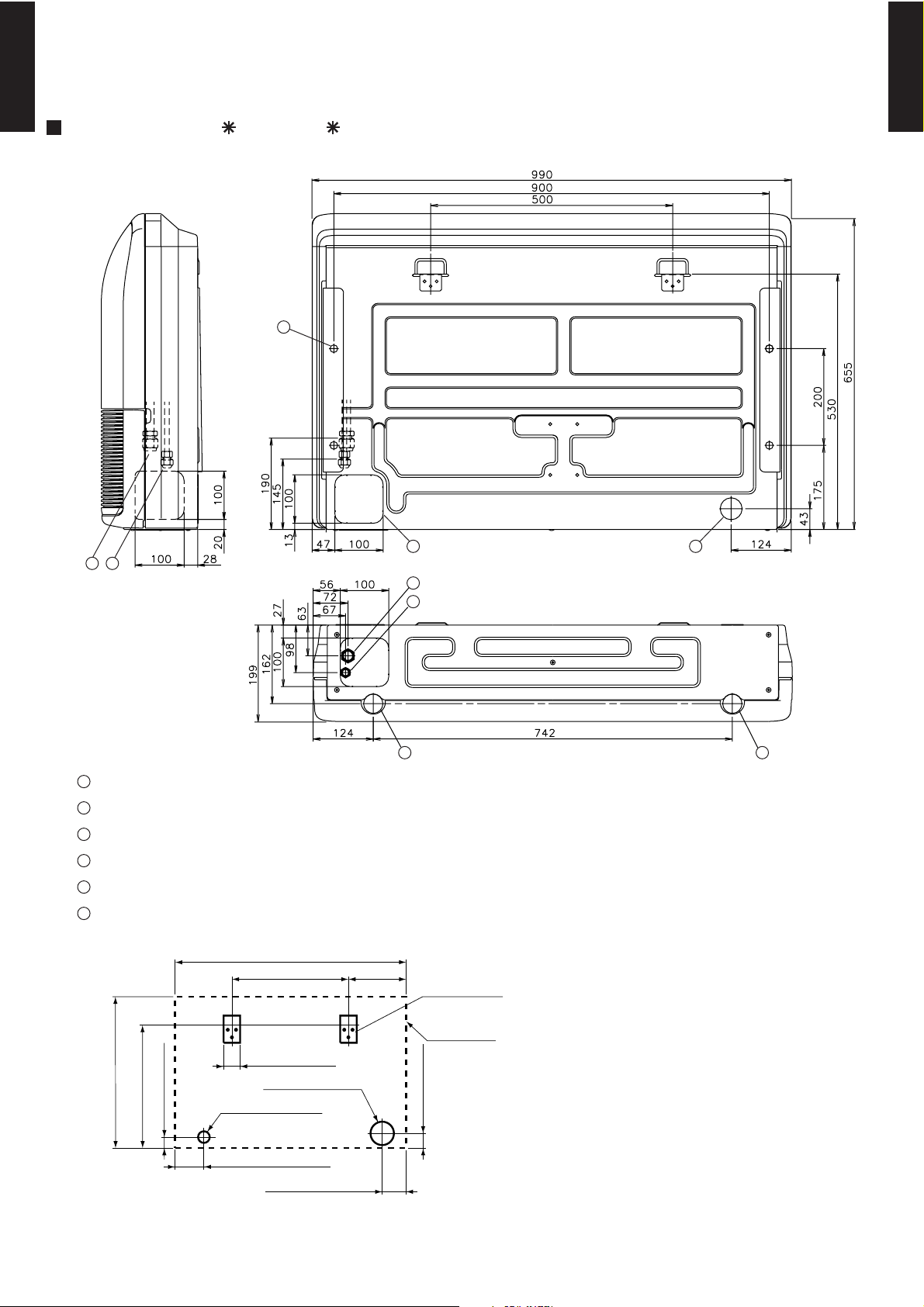
4-3. UNIVERSAL MODEL
MODELS : AB 14L, AB 18L
(Unit : mm)
100 hole
50 hole
125
100 hole
655
530
45
65
500 245
990
65
Wall bracket
Side of set
1
Refrigerant piping flare connection (Gas)
Refrigerant piping flare connection (Liquid)
Drain piping connection
Knock out hole for drain piping
Knock out hole for refrigerant piping
Hole for lifting bolt (Use M10 screw bolt)
2
3
4
5
6
1
2
3
45
6
3
1 2
Side view
Rear view
Bottom view
- (01 - 20) -
MULTI TYPE
2ROOM TYPE
MULTI TYPE
2ROOM TYPE
Ceiling
Left
Indoor unit
Right
Ceiling
150 or more 300 or more
20 or more
1000 or more
2300 or more
Left Right
300 or more300 or more
MOUNTING POSITION
Obstruction
Floor
(Unit : mm)
- (01 - 21) -
MULTI TYPE
2ROOM TYPE
MULTI TYPE
2ROOM TYPE
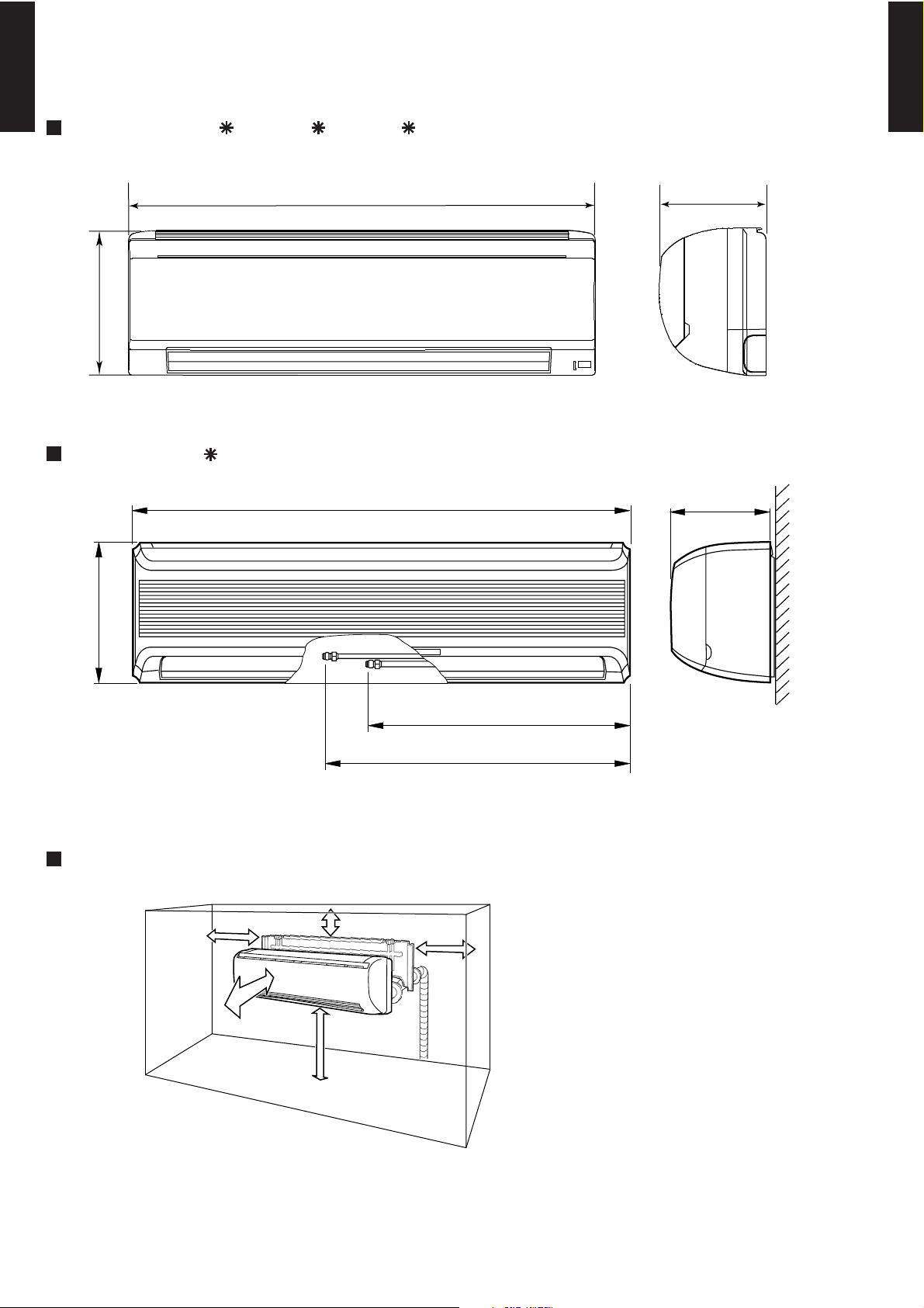
(Unit : mm)
MODELS : AS 7L, AS 9L, AS 12L
MODEL : AS 18L
257
808
Front view Side view
Front view
Side view
187
MOUNTING POSITION
1500 mm
or over
2300 mm or over
Right side
50 mm or over
Left side
50 mm or over
60 mm or over
1,120
626
711
320
220
4-4. WALL MOUNTED MODEL
- (01 - 22) -
MULTI TYPE
2ROOM TYPE
MULTI TYPE
2ROOM TYPE
5-1. DUCTED MODEL
MODELS : AR 9L, AR 12L, AR 14L, AR 18L
5. WIRING DIAGRAMS
CONTROL
BOARD
TO OUTDOOR
UNIT
TO REMOTE
CONTROL UNIT

- (01 - 23) -
MULTI TYPE
2ROOM TYPE
MULTI TYPE
2ROOM TYPE
5-2. CASSETTE MODEL
MODELS : AU 12L, AU 14L, AU 18L
CONTROL
BOARD
FAN MOTOR
CAPACITOR
- (01 - 24) -
MULTI TYPE
2ROOM TYPE
MULTI TYPE
2ROOM TYPE
5-3. UNIVERSAL MODEL
MODELS : AB 14L, AB 18L
TO OUTDOOR UNIT
CONTROL
BOARD
Use T3.15A 250V
FUSE on F101
- (01 - 25) -
MULTI TYPE
2ROOM TYPE
MULTI TYPE
2ROOM TYPE
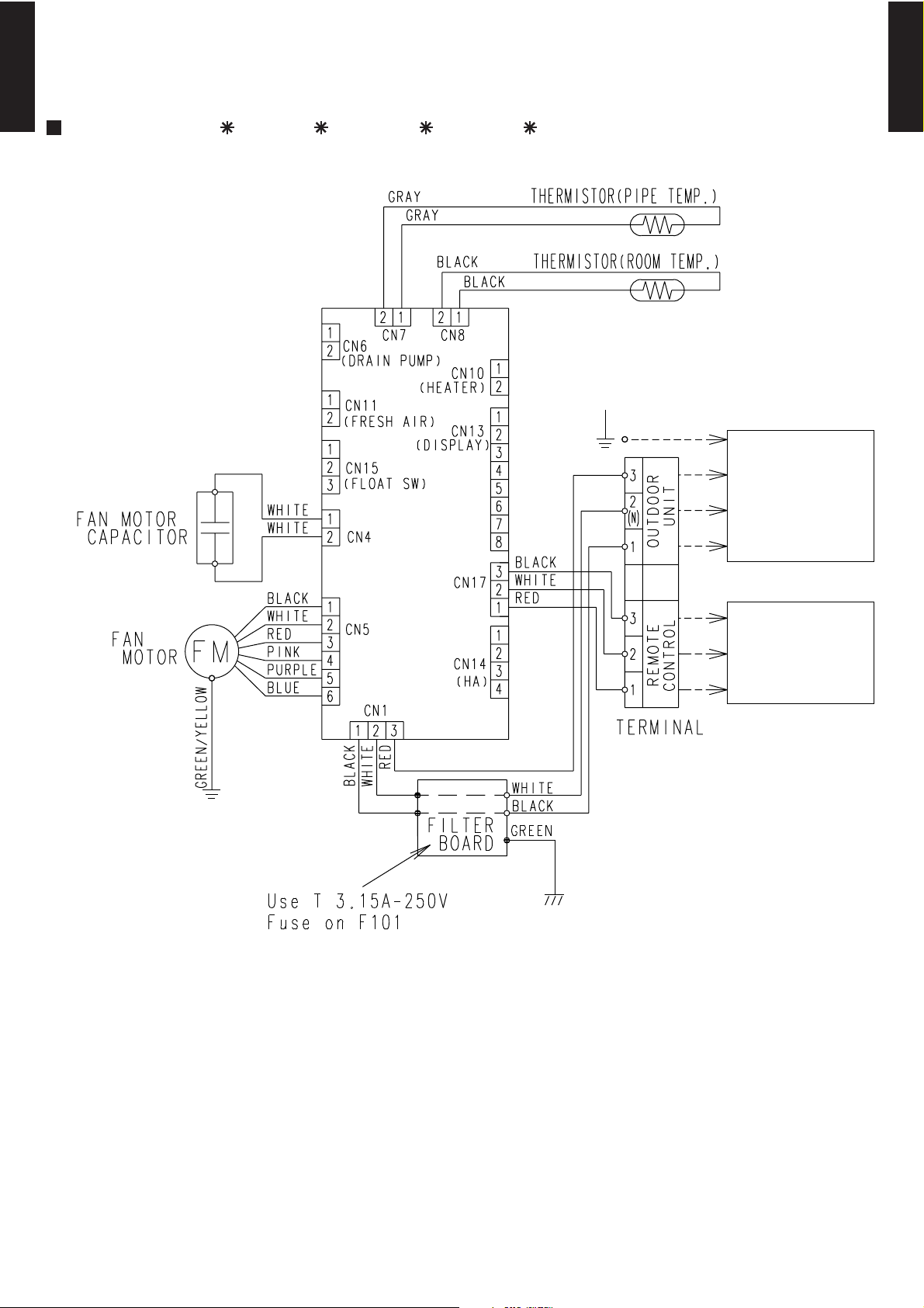
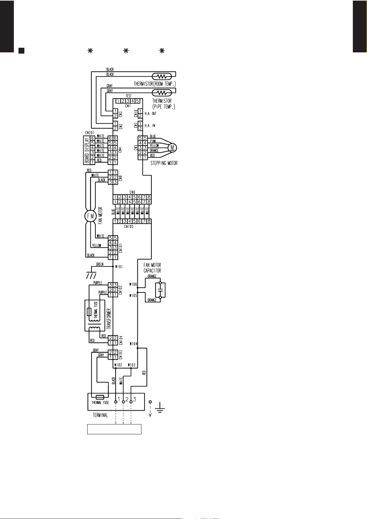
5-4. WALL MOUNTED MODEL
MODELS : AS 7L, AS 9L, AS 12L
CONTROL
BOARD
POWER
SUPPLY
BOARD
TO OUTDOOR UNIT
103°C
(N)
- (01 - 26) -
MULTI TYPE
2ROOM TYPE
MULTI TYPE
2ROOM TYPE
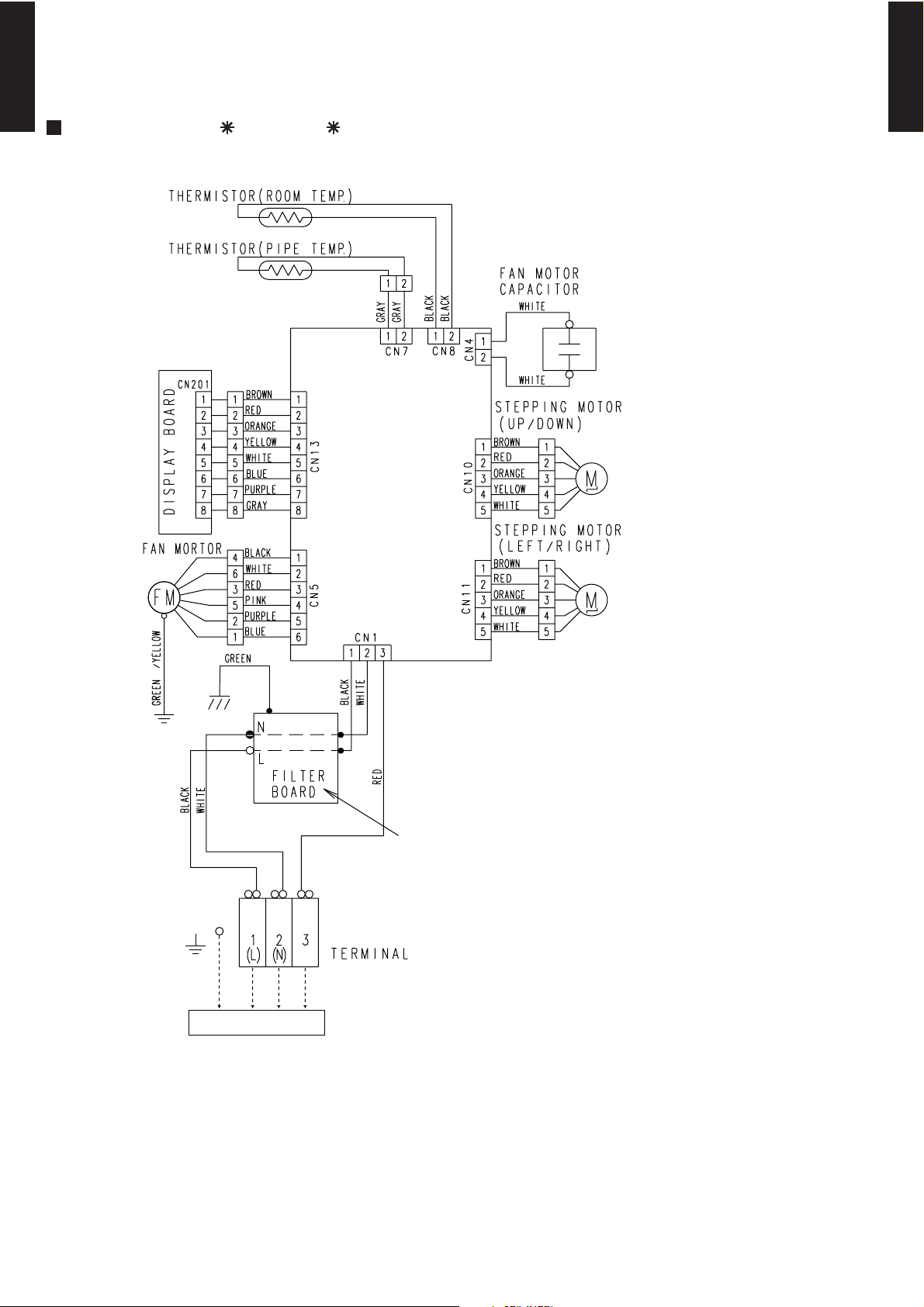
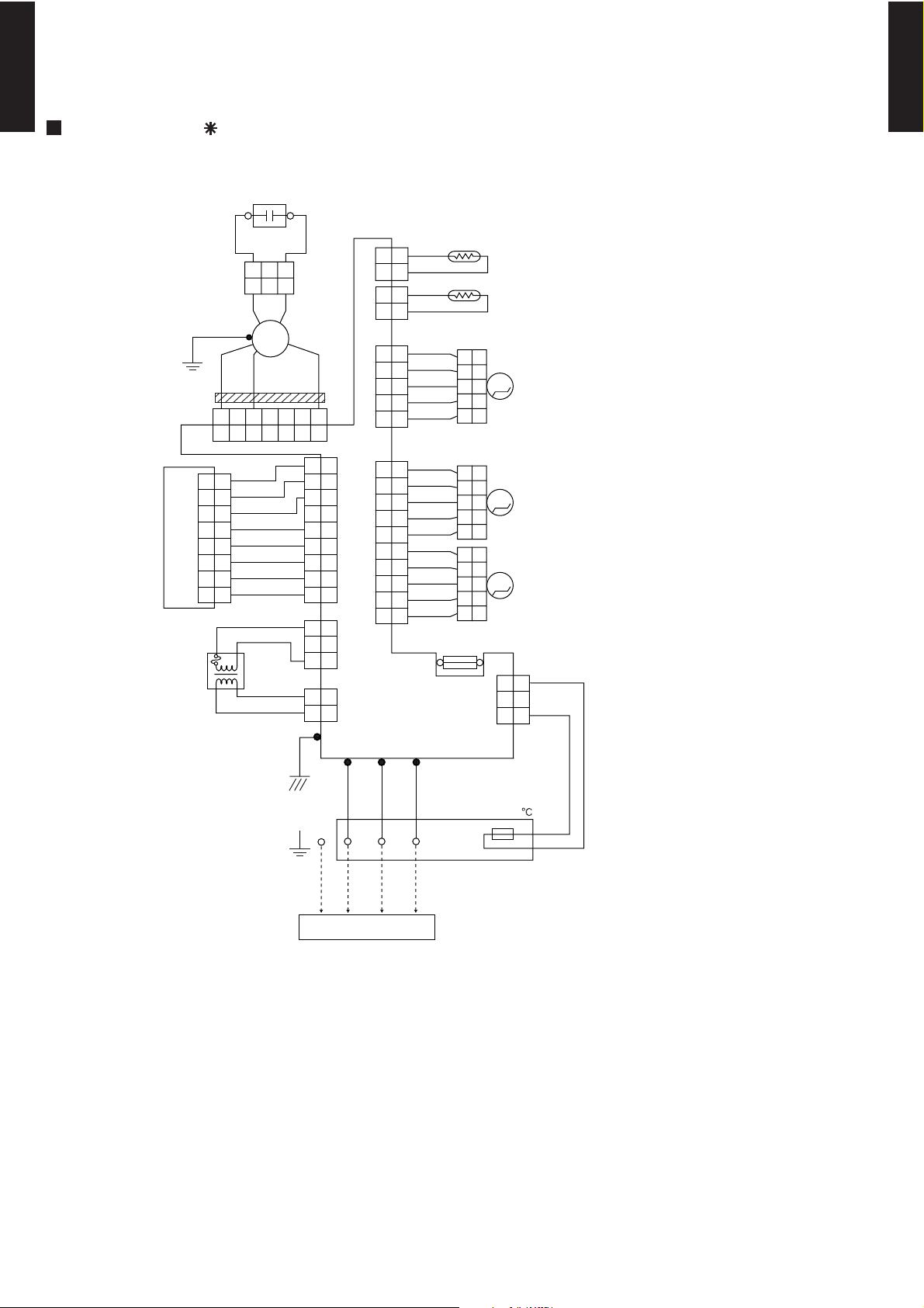
MODEL : AS 18L
TO OUTDOOR UNIT
(PIPE TEMP.)
GRAY
GRAY
WHITE
GREEN
GRAY
RED
GRAY
FM
(ROOM TEMP.)
(RIGHT/ LEFT)
(UP/DOWN)
BLACK
BLACK
WHITE
WHITE
WHITE
BLACK
BLUE
RED
RED
BLACK
GRAY
GRAY
GRAY
GRAY
YELLOW
PINK
GRAY
GRAY
GRAY
GRAY
GRAY
GRAY
GRAY
PURPLE
PURPLE
PURPLE
GRAY
GRAY
GRAY
GRAY
GRAY
(DIFFUSER)
GRAY
GRAY
GRAY
GRAY
RED
PINK
M
M
M
GREEN/
YELLOW
W1
E1
W2 W6
FAN MOTOR
CAPACITOR
THERMISTOR
FAN
MOTOR
TERMINAL
THERMISTOR
STEPPING
MOTOR
STEPPING
MOTOR
STEPPING
MOTOR
TRANSFORMER
CONTROL
BOARD
DISPLAY BOARD
CN2
CN4CN5CN9CN7
CN17
CN10CN16 CN1
CN201
THERMAL
FUSE 102
2
2
1
1
3
3
4
4
5
5
6
6
7
7
2
2
1
1
3
3
2
2
1
1
3
3
2
2
1
1
7
7
6
6
2
2
1
1
3
3
4
4
5
5
7
7
8
8
9
9
8
8
6
6
2
2
1
1
3
3
4
4
5
5
2
2
1
1
3
3
2
2
1
1
3
3
4
4
5
5
2
2
1
1
8
8
9
9
10
10
7
7
6
6
2
2
1
1
3
3
4
4
5
5
2
2
1
1
2
2
1
1
3
3
4
4
5
5
2
2
1
1
3
3
4
4
5
5
2
2
1
1
3
3
4
4
5
5
(N)(L)
123
FUSE T 3. 15A 250V
EMI FILTER
1T
- (01 - 27) -
MULTI TYPE
2ROOM TYPE
MULTI TYPE
2ROOM TYPE
6. CAPACITY TABLE
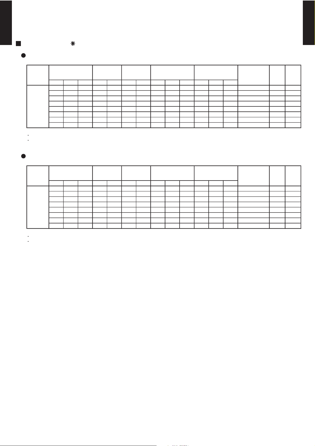
6-1. COMBINATIONS
MODEL : AO 18L2
COOLING
HEATING
Room 1 Room 2 Total Room 1 Room 2 Room 1 Room 2 Min. Rated Max. Min. Rated Max.
Min. 14 kBTU 7 7 14 2.20 2.20 2.50 2.50 2.00 4.40 5.00 0.68 1.41 1.71 3.12 B
Max. 24 kBTU 7 9 16 2.30 2.80 2.48 3.02 2.00 5.10 5.50 0.68 1.70 1.86 3.00 C
7 12 19 2.05 3.25 2.28 3.62 2.00 5.30 5.90 0.68 1.73 2.07 3.06 B
7 14 21 1.90 3.50 2.25 4.15 2.00 5.40 6.40 0.68 1.73 2.22 3.12 B
9 9 18 2.70 2.70 3.00 3.00 2.00 5.40 6.00 0.68 1.73 2.08 3.12 B
9 12 21 2.40 3.00 2.84 3.56 2.00 5.40 6.40 0.68 1.72 2.22 3.14 B
9 14 23 2.20 3.30 2.60 3.90 2.00 5.50 6.50 0.68 1.73 2.22 3.18 B
12 12 24 2.70 2.70 3.20 3.20 2.00 5.40 6.40 0.68 1.70 2.22 3.18 B
NOTES
Cooling capacity is based on 27°CDB/19°CWB (indoor temperature) , 35°CDB (outdoor temperature)
The total ability of connected a indoor unit is up to 27000BTU.
Cooling capacity
for each indoor
unit Rated (kW)
Total cooling capacity (kW)
Total Input (kW)
Cooling capacity
for each indoor
unit Max (kW)
Indoor model for each room
705
850
865
865
Annual energy
consumption
(KW/h)
EER
(kW/kW )
Class
865
860
865
850
Room 1 Room 2 Total Room 1 Room 2 Room 1 Room 2 Min. Rated Max. Min. Rated Max.
Min. 14 kBTU 7 7 14 2.60 2.60 3.20 3.20 2.20 5.20 6.40 0.68 1.57 2.13 3.31 C
Max. 24 kBTU 7 9 16 2.80 3.40 3.07 3.73 2.20 6.20 6.80 0.68 2.06 2.22 3.01 D
7 12 19 2.45 3.75 2.69 4.11 2.20 6.20 6.80 0.68 1.93 2.22 3.21 C
7 14 21 2.30 4.00 2.56 4.44 2.50 6.30 7.00 0.75 1.85 2.22 3.41 B
9 9 18 3.15 3.15 3.50 3.50 2.20 6.30 7.00 0.68 1.95 2.22 3.23 C
9 12 21 2.80 3.50 3.11 3.89 2.20 6.30 7.00 0.75 1.90 2.22 3.32 C
9 14 23 2.60 3.80 2.88 4.22 2.50 6.40 7.10 0.75 1.84 2.22 3.48 B
12 12 24 3.15 3.15 3.50 3.50 2.20 6.30 7.00 0.75 1.88 2.22 3.35 C
NOTES
Heating capacity is based on 20°CDB (indoor temperature) , 7°CDB/6°CWB (outdoor temperature)
The total ability of connected a indoor unit is up to 27000BTU.
Indoor model for each room
Heating capacity
for each indoor
unit Rated (kW)
Total heating capacity (kW)
Total Input (kW)
Heating capacity
for each indoor
unit Max (kW)
Annual energy
consumption
(KW/h)
COP
(kW/kW )
Class
785
1030
965
925
975
950
920
940
- (01 - 28) -
MULTI TYPE
2ROOM TYPE
MULTI TYPE
2ROOM TYPE
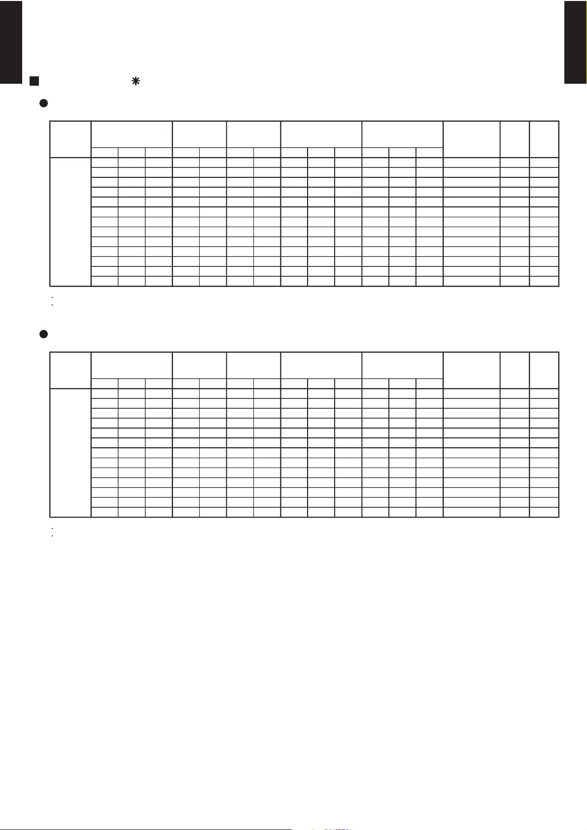
MODEL : AO 24L2
COOLING
HEATING
Room 1 Room 2 Total Room 1 Room 2 Room 1 Room 2 Min. Rated Max. Min. Rated Max.
Min. 14 kBTU 7 7 14 2.20 2.20 2.50 2.50 2.00 4.40 5.00 0.68 1.41 1.71 705 3.12 B
Max. 30 kBTU 7 9 16 2.30 2.80 2.48 3.02 2.00 5.10 5.50 0.68 1.70 1.86 850 3.00 C
7 12 19 2.05 3.25 2.28 3.62 2.00 5.30 5.90 0.68 1.73 2.07 865 3.06 B
7 14 21 1.90 3.50 2.39 4.41 2.00 5.40 6.80 0.68 1.73 2.60 865 3.12 B
7 18 25 1.70 4.00 2.27 5.33 2.00 5.70 7.60 0.68 1.73 2.77 865 3.29 A
9 9 18 2.70 2.70 3.00 3.00 2.00 5.40 6.00 0.68 1.73 2.08 865 3.12 B
9 12 21 2.40 3.00 2.98 3.72 2.00 5.40 6.70 0.68 1.72 2.58 860 3.14 B
9 14 23 2.20 3.30 2.92 4.38 2.00 5.50 7.30 0.68 1.73 2.77 865 3.18 B
9 18 27 2.00 3.80 2.66 5.04 2.50 5.80 7.70 0.80 1.73 2.77 865 3.35 A
12 12 24 2.75 2.75 3.55 3.55 2.00 5.50 7.10 0.68 1.70 2.77 850 3.24 A
12 14 26 2.60 3.00 3.44 3.96 2.00 5.60 7.40 0.68 1.73 2.77 865 3.24 A
12 18 30 2.30 3.50 3.09 4.71 2.50 5.80 7.80 0.80 1.73 2.77 865 3.35 A
14 14 28 2.85 2.85 3.85 3.85 2.50 5.70 7.70 0.80 1.74 2.77 870 3.28 A
NOTES
Cooling capacity is based on 27°CDB/19°CWB (indoor temperature) , 35°CDB (outdoor temperature)
The total ability of connected a indoor unit is up to 27000BTU.
Class
EER
(kW/kW )
Cooling capacity
for each indoor
unit Max.(kW)
Indoor model for each room
Cooling capacity
for each indoor
unit Rated(kW)
Total cooling capacity (kW)
Total Input (kW)
Annual energy
consumption
(KW/h)
Room 1 Room 2 Total Room 1 Room 2 Room 1 Room 2 Min. Rated Max. Min. Rated Max.
Min. 14 kBTU 7 7 14 2.60 2.60 3.20 3.20 2.20 5.20 6.40 0.68 1.57 2.11 785 3.31 C
Max. 30 kBTU 7 9 16 2.80 3.40 3.25 3.95 2.20 6.20 7.20 0.68 2.05 2.53 1025 3.02 D
7 12 19 2.45 3.75 3.00 4.60 2.20 6.20 7.60 0.68 1.93 2.77 965 3.21 C
7 14 21 2.30 4.10 2.88 5.13 2.50 6.40 8.00 0.75 1.85 2.77 925 3.46 B
7 18 25 1.90 4.50 2.61 6.19 2.50 6.40 8.80 0.75 1.72 2.77 860 3.72 A
9 9 18 3.20 3.20 3.90 3.90 2.20 6.40 7.80 0.68 1.95 2.77 975 3.28 C
9 12 21 2.80 3.50 3.56 4.44 2.20 6.30 8.00 0.75 1.90 2.77 950 3.32 C
9 14 23 2.60 3.80 3.33 4.87 2.50 6.40 8.20 0.75 1.80 2.77 900 3.56 B
9 18 27 2.20 4.20 3.06 5.84 2.70 6.40 8.90 0.80 1.64 2.77 820 3.90 A
12 12 24 3.20 3.20 4.00 4.00 2.20 6.40 8.00 0.75 1.88 2.77 940 3.40 C
12 14 26 3.00 3.40 3.94 4.46 2.50 6.40 8.40 0.80 1.77 2.77 885 3.62 A
12 18 30 2.40 4.00 3.38 5.63 2.70 6.40 9.00 0.80 1.64 2.77 820 3.90 A
14 14 28 3.20 3.20 4.40 4.40 2.70 6.40 8.80 0.80 1.75 2.77 875 3.66 A
NOTES
Heating capacity is based on 20°CDB (indoor temperature) , 7°CDB/6°CWB (outdoor temperature)
The total ability of connected a indoor unit is up to 27000BTU.
Class
Annual energy
consumption
(KW/h)
Heating capacity
for each indoor
unit Max. (kW)
Indoor model for each room
COP
(kW/kW )
Heating capacity
for each indoor
unit Rated (kW)
Total heating capacity (kW)
Total Input (kW)
 Loading...