


40-913
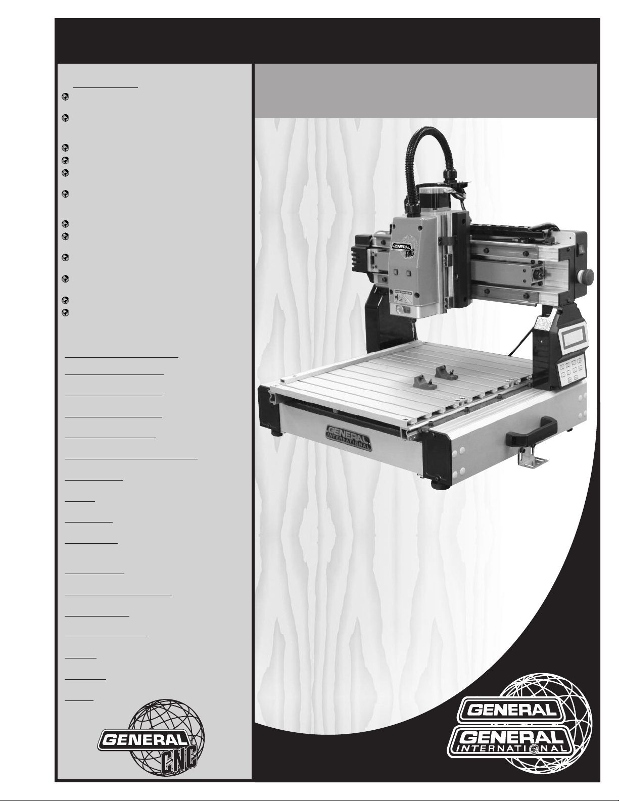
SETUP & OPERATION MANUAL
FEATURES
asy start-up procedure and unrivalled tech-
E
nical support.
arge user-friendly control panel with LCD dis-
L
lay, keypad and USB 2.0 port for easy file
p
transfers.
endant style hand-held operating contoller.
P
asy to learn i-Picture programming software.
E
Low backlash stepper motors for excellent
erformance and low maintenance.
p
Sliding table with rack and pinion transmis-
sion on "Y" axis and lead screw for "X" and "Z"
xis.
a
Positional accuracy up to 0.001 inches.
Variable cutting speeds up to 118 inches per
minute.
50 watt spindle included with automatic
1
spindle on/off control.
luminum table with integrated hold down
A
lamps.
c
Tool kit with starter cutting tools included.
Controller included, no external operating PC
required.
13" x 18" CNC CARVING MACHINE
SPECIFICATIONS
X AXIS CUTTING CAPACITY
13" (330 MM)
Y AXIS CUTTING CAPACITY
18" (457 MM)
Z AXIS CUTTING CAPACITY
3" (76 MM)
POSITIONAL ACCURACY
0.001”
OVERALL DIMENSIONS (W X L X H)
27 1/2” X 23 5/8”X 27 1/2” (699 X 540 X 699 MM)
SPINDLE SPEED
15 000 RPM
SPINDLE
150 WATT SPINDLE WITH BRUSHLESS MOTOR
MOTOR TYPE
LOW BACKLASH STEPPER MOTOR
BEARING TYPE
ALUMINUM BLOCK WITH REPLACEABLE NYLON
SLEEVES
TABLE SURFACE
ALUMINUM
PROGRAMMING SOFTWARE
i-Picture (included)
CUTTING SPEEDS
VARIABLE - UP TO 118 INCHES PER MINUTES
POWER REQUIREMENT
110 V, 2A
COLLETS
1/4” (6 MM)
WARRANTY
1 YEAR LIMITED
WEIGHT
62 LBS (18 KG)
MODEL
i-Carver
#40-913
REVISION 1 - NOVEMBER 19/2012
© Copyright General® International 11/2012

GENERAL® INTERNATIONAL
8360 Champ-d’Eau, Montreal (Quebec) Canada H1P 1Y3
Telephone (514) 326-1161 • Fax (514) 326-5555 • www.general.ca
THANK YOU for choosing this General
®
International model i-Carver 40-913.This
13” x 18” CNC carving machine has been carefully tested and inspected before shipment and
if properly used and maintained, will provide you with years of reliable service. For your safety, as well as to ensure optimum performance and trouble-free operation, and to get the most
from your investment, please take the time to read this manual before assembling, installing
and operating the unit.
The manual’s purpose is to familiarize you with the safe operation, basic function, and features
of this CNC carving machine as well as the set-up, maintenance and identification of its parts
and components. This manual is not intended as a substitute for formal woodworking instruction, nor to offer the user instruction in the craft of woodworking. If you are not sure about the
safety of performing a certain operation or procedure, do not proceed until you can confirm,
from knowledgeable and qualified sources, that it is safe to do so.
Once you’ve read through these instructions, keep this manual handy for future reference.
Disclaimer: The information and specifications in this
manual pertain to the unit as it was supplied from the
factory at the time of printing. Because we are committed to making constant improvements, General
International reserves the right to make changes to
components, parts or features of this unit as deemed
necessary,without prior notice and without obligation to
install any such changes on previously delivered units.
Reasonable care is taken at the factory to ensure that
the specifications and information in this manual corresponds with that of the unit with which it was supplied.
However, special orders and “after factory” modifications may render some or all information in this manual
inapplicable to your machine. Further, as several gene-
®
rations of this model of CNC carving machine and several versions of this manual may be in circulation, if you
own an earlier or later version of this unit, this manual
may not depict your machine exactly. If you have any
doubts or questions contact your retailer or our support
line with the model and serial number of your unit for
clarification.
GENERAL®& GENERAL®INTERNATIONAL WARRANTY
All component parts of General International, General CNC and Excalibur by General
International products are carefully inspected during all stages of production and each unit is
thoroughly inspected upon completion of assembly.
Standard 2-Year Limited Warranty
Because of our commitment to quality and customer satisfaction, General International
agrees to repair or replace any part or component which upon examination, proves to be
defective in either workmanship or material to the original purchaser for a period of 2 years
(24 months) from the date of purchase, subject to the “conditions and exceptions” as listed
below.
To file a Claim
To file a claim under our Standard 2-year Limited Warranty, all defective parts, components or
machinery must be returned freight or postage prepaid to General International or to a nearby
distributor, repair center or other location designated by General International. For further details
call our CNC technical support department at 1-877-340-8989 or submit a Technical Support
Ticket Request at http://generalcnc.ca/support_request.
Along with the return of the product being claimed for warranty, a copy of the original proof
of purchase and a “letter of claim” must be included (a warranty claim form can also be used
and can be obtained, upon request, from General International or an authorized distributor)
clearly stating the model and serial number of the unit (if applicable) and including an explanation of the complaint or presumed defect in material or workmanship.
CONDITIONS AND EXCEPTIONS:
This coverage is extended to the original purchaser only. Prior warranty registration is not
required but documented proof of purchase i.e. a copy of original sales invoice or receipt
showing the date and location of the purchase as well as the purchase price paid, must be
provided at the time of claim.
Warranty does not include failures, breakage or defects deemed after inspection by General®
International to have been directly or indirectly caused by or resulting from; improper use, or
lack of or improper maintenance, misuse or abuse, negligence, accidents, damage in handling or transport, or normal wear and tear of any generally considered consumable parts or
components.
Repairs made without the written consent of General® Internationallwill void all warranty.

TABLE OF CONTENTS
Rules for safe operation . . . . . . . . . . . . . . .5
Electrical requirements . . . . . . . . . . . . . . .6
Grounding instructions . . . . . . . . . . . . . . . . . . . . . . .6
Circuit capacity . . . . . . . . . . . . . . . . . . . . . . . . . . . . .6
Extension cords . . . . . . . . . . . . . . . . . . . . . . . . . . . . .6
Identification of main parts
and components . . . . . . . . . . . . . . . . . . . .
Unpacking and preparation for set-up and
installation . . . . . . . . . . . . . . . . . . . . . . . .
Safety . . . . . . . . . . . . . . . . . . . . . . . . . . . . . . . . . . . . . .8
Unpacking . . . . . . . . . . . . . . . . . . . . . . . . . . . . . . . . .8
Placement within the shop /
Establishing a safety zone . . . . . . . . . . . . .
Installation and Assembly instructions . .10-11
Installation . . . . . . . . . . . . . . . . . . . . . . . . . . . . . . . .10
Optional stand . . . . . . . . . . . . . . . . . . . . . . . . . . . . .10
Adjusting the leveling feet . . . . . . . . . . . . . . . . . . .10
Mounting to a work surface . . . . . . . . . . . . . . . . . .10
Install the collet and collet nut . . . . . . . . . . . . . . .11
Cutting tool installation / removal . . . . . . . . . . . .11
Operating instructions . . . . . . . . . . . . . . .18
oint or origin . . . . . . . . . . . . . . . . . . . . . . . . . . . . . .18
P
Secure the workpiece . . . . . . . . . . . . . . . . . . . . . . .18
Load a GEE file for carving . . . . . . . . . . . . . . . . . . .18
Position the spindle over the point of origin . . . .20
Checking size of your image . . . . . . . . . . . . . . . . .21
Starting to carve . . . . . . . . . . . . . . . . . . . . . . . . . . .21
Speed selection . . . . . . . . . . . . . . . . . . . . . . . . . . . .21
Pause function . . . . . . . . . . . . . . . . . . . . . . . . . . . . .22
7
Concave carving on acrylic . . . . . . . . . . . . . . . . . .22
8
Advanced Operations . . . . . . . . . . . . . . . . . . . . . . . . .23
Using same point of origin as previous project .23
Manually adjusting jogging speed . . . . . . . . . . .23
Spindle manual positioning . . . . . . . . . . . . . . . . . .23
Turning spindle motor off/on . . . . . . . . . . . . . . . . .24
9
Changing unit setting from metric to imperial . .24
M3 Code . . . . . . . . . . . . . . . . . . . . . . . . . . . . . . . . . .24
Maintenance . . . . . . . . . . . . . . . . . . . .25-26
Periodic maintenance . . . . . . . . . . . . . . . . . . . . . .25
Lubrication . . . . . . . . . . . . . . . . . . . . . . . . . . . . . . . .25
Recommended optional accessories . . . . .26
i-Picture
i-Picture installation . . . . . . . . . . . . . . . . . . . . . . . . .12
Formatting your image files for i-Picture software .12
Converting a file to GEE code . . . . . . . . . . . . . . . .13
Settings . . . . . . . . . . . . . . . . . . . . . . . . . . . . . . . . . . .13
Preview . . . . . . . . . . . . . . . . . . . . . . . . . . . . . . . . . . .15
Convert . . . . . . . . . . . . . . . . . . . . . . . . . . . . . . . . . . .16
Exit software . . . . . . . . . . . . . . . . . . . . . . . . . . . . . . .16
Transfer GEE code file to usb flash drive . . . . . . . .16
software . . . . . . . . . . . . . . . . .12-16
Basic adjustments and controls . . . . . . . . . . .17
Connecting to a power source . . . . . . . . . . . . . . .17
On/Off power switch . . . . . . . . . . . . . . . . . . . . . . . .17
Indicator lights . . . . . . . . . . . . . . . . . . . . . . . . . . . . .17
Parts list & diagrams . . . . . . . . . . . . . .27-31
Contact information . . . . . . . . . . . . . . . . .32

RULES FOR SAFE OPERATION
To help ensure safe operation, please take a moment to learn the machine’s applications and limitations, as well as potential hazards. General® International disclaims any real or implied warranty and holds itself harmless for any injury that
ay result from improper use of its equipment.
m
1. Be sure to read and understand owner’s manual
before operating.
2. Do not operate the i-Carver when tired, distracted,
r under the effects of drugs, alcohol or any med-
o
ication that impairs reflexes or alertness.
3. The working area should be well lit, clean and free
of debris.
4. Keep children and visitors at a safe distance when
the i-Carver is in operation; do not permit them to
operate the i-Carver.
5. Childproof and tamper proof your shop and all
machinery with locks, master electrical switches
and switch keys, to prevent unauthorized or unsupervised use.
6. Stay alert! Give your work your undivided atten-
tion. Even a momentary distraction can lead to serious injury.
7. Fine particulate dust is a carcinogen that can be
hazardous to health. Work in a well-ventilated area
and whenever possible use a dust collector and
wear eye, ear and respiratory protection devices.
8. Do not wear loose clothing, gloves, bracelets, neck-
laces or other jewelry while the i-Carver is in operation. Wear protective hair covering to contain long
hair and wear non-slip footwear.
9. Be sure that adjusting wrenches, tools, drinks and
other clutter are removed from the machine before
operating.
14. Always disconnect the tool from the power source
before servicing, changing accessories, performing any maintenance or cleaning, or if the
machine will be left unattended.
15. Make sure that switch is in
plugging in the power cord.
16. Make sure the tool is properly grounded. If equip-
ped with a 3-prong plug it should be used with a
three-pole receptacle. Never remove the third
prong.
17. Do not use this i-Carver for any purpose other than
its intended use. If used for other purposes,
AL INTERNATIONAL
warranty and holds itself harmless for any injury,
which may result from that use.
18. To reduce the risk of electric shock, do not operate
the machine with wet hands.
19. Be sure to read and understand every warning la-
bel before operating the machine. Make sure all
warning labels appear on the machine as indicated in section “Labels” on next page and that they
are fully legible. Immediately replace any illegible
or missing label before using the machine.
20. Respect the rated limits of this machine.
21. To ensure safety, all maintenance should be perfor-
med by a qualified technician.
22. To avoid electrical shock, do not touch the transfor-
mers, motors or control box when the power is on.
disclaims any real or implied
the “OFF”
position before
GENER-
10. Keep hands well away from the spindle, cutting
tools, and all moving parts. Use a brush, not hands,
to clear away chips and dust.
11. Before turning on the i-Carver, make sure the work-
piece is properly secured.
12. Use of parts and accessories NOT recommended
by
GENERAL INTERNATIONAL
ment malfunction or risk of injury.
13. Never stand on machinery. Serious injury could
result if the tool is tipped over.
may result in equip-
23. Make sure to always have full unimpeded access
to the emergency stop button at all times.
24. To ensure safety, do not tamper with the safety
cover, limit switch or any other accessories.
25. Be sure to keep a record before changing any set-
ting on the machine.
26. Place the unit on a sturdy surface, in a dry area.
27. Avoid exposing the machine to extremely high
temperatures.
28. Unplug the unit from the power source before
replacing fuses. Use only recommended fuses.
29. Be sure to turn off the machine when the power
source is unstable.
5
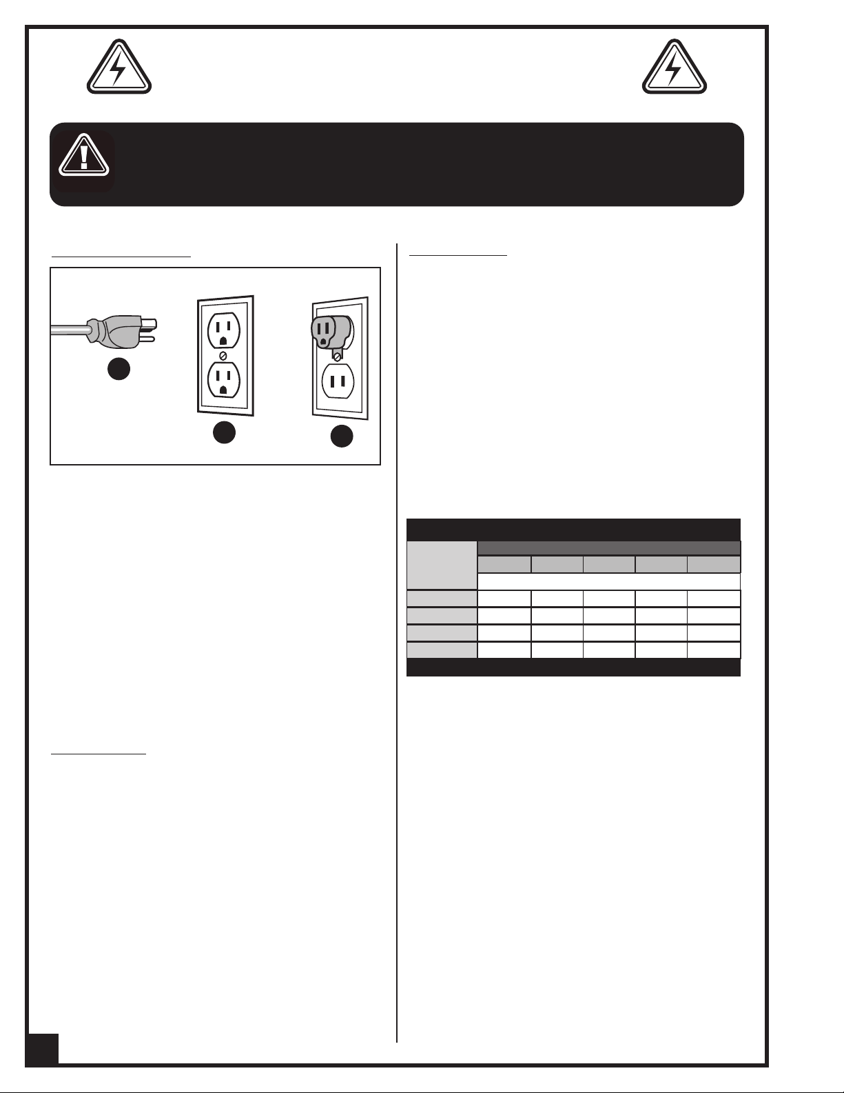
ELECTRICAL REQUIREMENTS
BEFORE CONNECTING THE MACHINE TO THE POWER SOURCE, VERIFY THAT THE VOLTAGE OF YOUR POWER SUPPLY CORRE-
PONDS WITH THE VOLTAGE SPECIFIED ON THE MOTOR I.D. NAMEPLATE. A POWER SOURCE WITH GREATER VOLTAGE THAN
S
NEEDED CAN RESULT IN SERIOUS INJURY TO THE USER AS WELL AS DAMAGE TO THE MACHINE. IF IN DOUBT, CONTACT A QUAL-
FIED ELECTRICIAN BEFORE CONNECTING TO THE POWER SOURCE.
I
HIS TOOL IS FOR INDOOR USE ONLY. DO NOT EXPOSE TO RAIN OR USE IN WET OR DAMP LOCATIONS.
T
GROUNDING INSTRUCTIONS
A
B
In the event of an electrical malfunction or short circuit, grounding reduces the risk of electric shock. The
motor of this machine is wired for 110V single phase
operation and is equipped with a 3-conductor cord
and a 3-prong grounding plug A to fit a grounded
type receptacle B. Do not remove the 3rd prong
(grounding pin) to make it fit into an old 2-hole wall
socket or extension cord. If an adaptor plug is used C,
it must be attached to the metal screw of the receptacle.
Note: The use of an adaptor plug is illegal in some
areas. Check your local codes. If you have any doubts
or if the supplied plug does not correspond to your
electrical outlet, consult a qualified electrician before
proceeding.
C
EXTENSION CORDS
If you find it necessary to use an extension cord with your
machine, use only 3-wire extension cords that have 3prong grounding plug and a matching 3-pole receptacle that accepts the tool’s plug. Repair or replace a
damaged extension cord or plug immediately.
Make sure the cord rating is suitable for the amperage
listed on the motor I.D. plate. An undersized cord will
cause a drop in line voltage resulting in loss of power
and overheating. In some cases this may cause the
machine to stop its cutting operation and an error message will appear on your controller.
The accompanying chart shows the correct size extension cord to be used based on cord length and motor
I.D. plate amp rating. If in doubt, use the next heavier
gauge. The smaller the number, the heavier the gauge.
TABLE - MINIMUM GAUGE FOR CORD
AMPERE
RATING
< 5
6 TO 10
10 TO 12
12 TO 16
* NR = Not Recommended
110 VOLTS 50 FEET 100 FEET 200FEET 300 FEET
------->
------->
------->
------->
TOTAL LENGTH OF CORD IN FEET
AWG
18 16 16 14
18 16 14 12
16 16 14 12
14 12 * NR * NR
CIRCUIT CAPACITY
Make sure that the wires in your circuit are capable of
handling the amperage draw from your machine, as
well as any other machines that could be operating
on the same circuit. If you are unsure, consult a qualified electrician. If the circuit breaker trips or the fuse
blows regularly, your machine may be operating on a
circuit that is close to its amperage draw capacity.
However, if an unusual amperage draw does not exist
and a power failure still occurs, contact a qualified
technician or our service department.
6
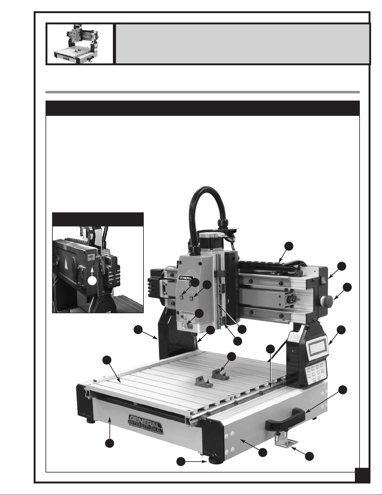
13” x 18” CNC CARVING MACHINE
MODEL i-Carver 40-913
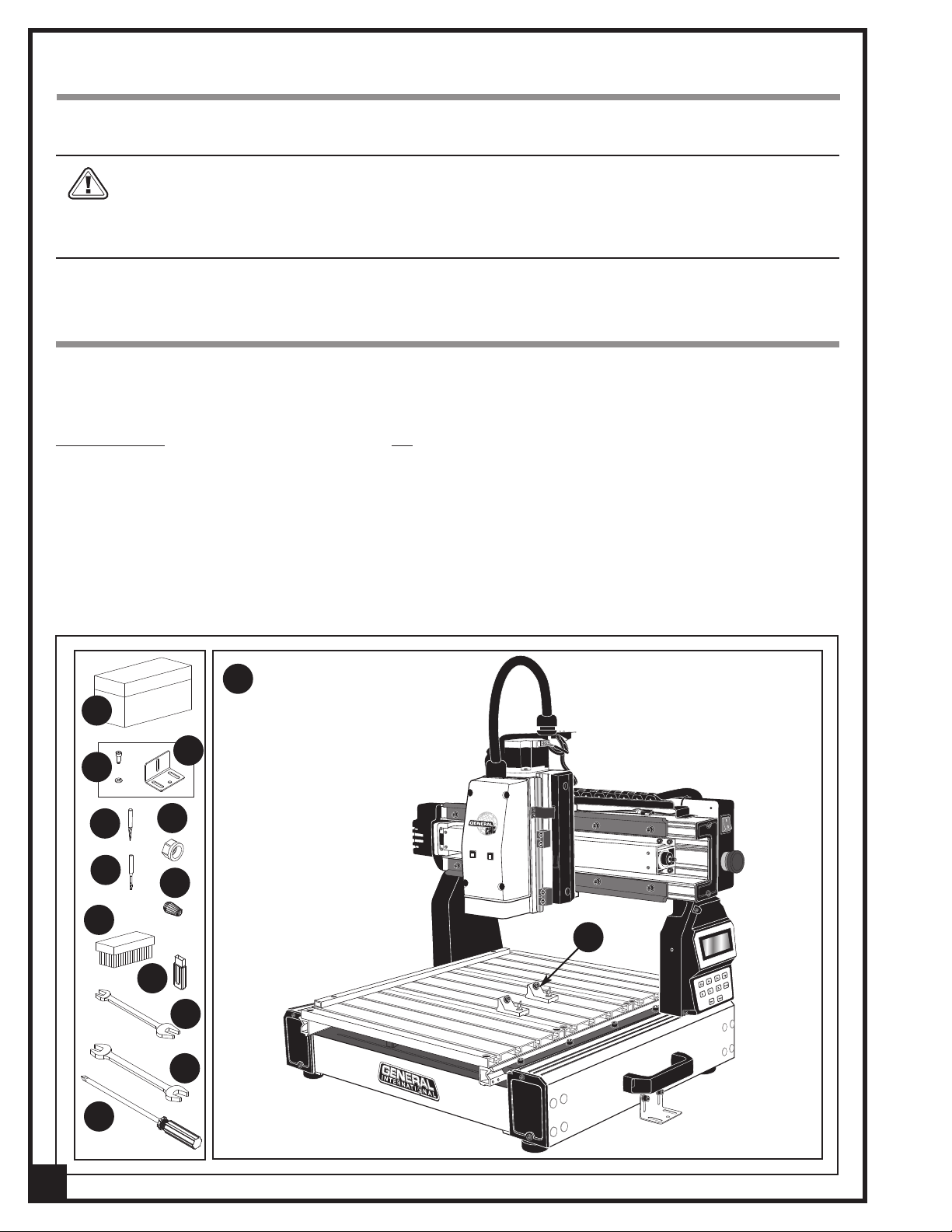
IDENTIFICATION OF MAIN PARTS AND COMPONENTS
MAIN ASSEMBLY - FRONT VIEW
A- FRAME
B- SIDE RAIL
C- WORK TABLE
D- GANTRY
E- Y AXIS SYSTEM
F- CABLE CHAIN
G- Z AXIS SYSTEM
H- SLIDE BLOCK
I- SPINDLE LOCKING BUTTON
J- CUTTING TOOL (BIT)
K- HAND-HELD PENDANT CONTROLLER
LEFT SIDE VIEW
N
L- WORKPIECE CLAMPS
M- STATUS LIGHT
N- USB PORT
O- SECURING BRACKETS
P- LEVELING FEET
Q- SYSTEM ERROR WARNING LIGHT
R- POWER ON/OFF SWITCH
S- STOP BUTTON
T- HANDLE
M
Q
F
R
S
I
D
C
A
P
J
G
H
E
L
B
O
K
T
7
UNPACKING AND PREPARATION FOR SET-UP & INSTALLATION
SAFETY
THE MACHINE IS HEAVY (62 LBS - 28 KG). DO NOT OVEREXERT. ARRANGE TO HAVE HELP NEARBY AND READY FOR
UNPACKING AND SET UP.
THE SOUND LEVEL OF THIS MACHINE IS RATED AT APPROXIMATELY 85-95 DB DURING OPERATION. MAKE SURE THAT
ADEQUATE HEARING PROTECTION IS USED AND THAT THE OVERALL SOUND LEVEL WITHIN THE WORKING ENVIRONMENT IS TAKEN INTO CONSIDERATION.
UNPACKING
Carefully unpack and remove the i-Carver and its components from the box and check for damaged or missing
items as per the list of contents below.
NOTE: Please report any damaged or missing items to your General International distributor immediately.
LIST OF CONTENTS QTY
A- TOOL BOX..............................................................................1
B- SOCKET SCREW W/WASHER .................................................2
C- SECURING BRACKETS............................................................2
D- 1/32" CONICAL/CARVING CUTTING TOOL........................1
E- 1/8" END MILL/MACHINING TOOL......................................1
F- ER11 COLLET NUT ..................................................................1
G- ER11 0.25" COLLET.................................................................1
H- BRUSH.....................................................................................1
M
A
C
B
D
F
E
G
H
I- USB FLASH DRIVE (including i-Picture software,
manual and 3D sample pictures) ................................1
J- 11-13 MM OPEN END WRENCH ...........................................1
K- 14-17 MM OPEN END WRENCH ...........................................1
L- PHILLIPS SCREWDRIVER.........................................................1
M- i-Carver .................................................................................1
N- WORKPIECE CLAMPS ............................................................2
N
I
J
K
L
8
PLACEMENT WITHIN THE SHOP / ESTABLISHING A SAFETY ZONE
THIS i-Carver 40-913 IS HEAVY – 62 LBS (28 KG). DO NOT OVER-EXERT. THE HELP OF AN ASSISTANT WILL BE NEEDED
OR THE INSTALLATION.
F
ERIOUS PERSONAL INJURY COULD OCCUR IF YOU CONNECT THE MACHINE TO THE POWER SOURCE BEFORE YOU HAVE COM-
S
LETED THE INSTALLATION AND ASSEMBLY STEPS. DO NOT CONNECT THE MACHINE TO THE POWER SOURCE UNTIL INSTRUCTED
P
TO DO SO.
PLACEMENT WITHIN THE SHOP
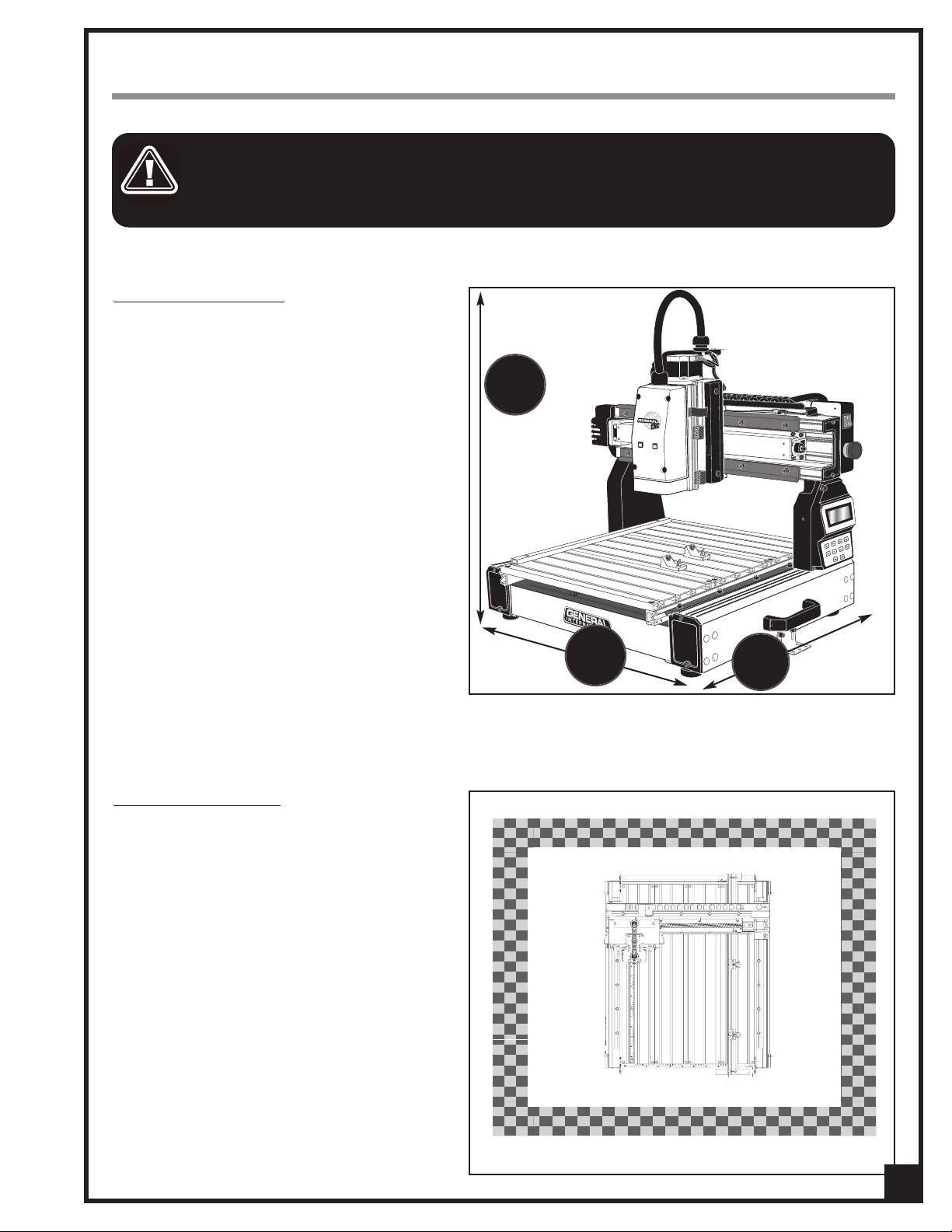
This machine should be installed and operated
only on a solid, flat and stable work surface that is
able to support the weight of the i-Carver and the
workpiece.
Using the dimensions shown as a guideline, plan
for placement within your shop that will allow the
operator to work unencumbered and unobstructed by foot traffic (either passing shop visitors or
other shop workers) or other tools or machinery.
27
/2
1
”
ESTABLISHING A SAFETY ZONE
For shops with frequent visitors or multiple operators, it is advisable to establish a safety zone
around shop machinery. A clearly defined “nogo” zone on the floor around each machine can
help avoid accidents that could cause injury to
either the operator or the shop visitor.
It is advisable to take a few moments to either
paint (using non-slip paint) or using tape, define
on the floor the limits or perimeter of each
machines safety zone. Take steps to ensure that
all operators and shop visitors are aware that
these areas are off limits whenever a machine is
running for everyone but the individual operating the unit.
23
5/8
”
27
1/2
”
9
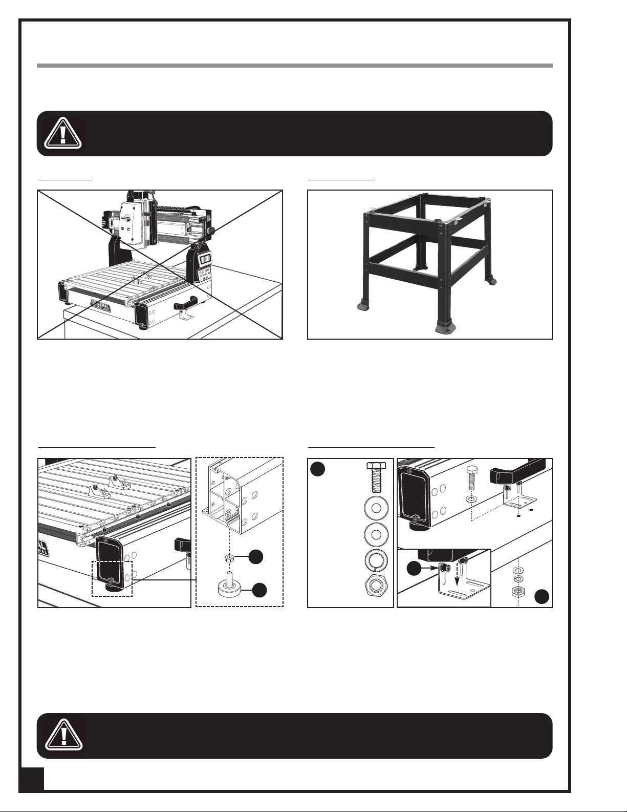
INSTALLATION AND ASSEMBLY INSTRUCTIONS
For your convenience this i-Carver is shipped from the factory partially assembled and requires only minimal
assembly and set up before being put into service.
SERIOUS PERSONAL INJURY COULD OCCUR IF YOU CONNECT THE MACHINE TO THE POWER SOURCE BEFORE YOU HAVE COM-
LETED THE INSTALLATION AND ASSEMBLY STEPS. DO NOT CONNECT THE MACHINE TO THE POWER SOURCE UNTIL INSTRUCTED
P
TO DO SO.
INSTALLATION
This machine should be installed and operated only
on a flat, sturdy and stable surface able to support the
weight of the machine (62 lbs - 28 kg) and the workpiece with ease.
Note: Never install the machine over the edge of a table
or workbench.
ADJUSTING THE LEVELING FEET
OPTIONAL STAND
If you prefer, an optional Heavy-duty open stand,
item #40-903, is available from your local General
International dealer.
MOUNTING TO A WORK SURFACE
C
HEX HEAD BOLT
After the i-Carver is placed in its final location, level the
feet by adjusting nut A up or down on the leveling feet
B as needed, then tightening down the nut.
FOR YOUR SAFETY IT IS ESSENTIAL THAT THE MACHINE DOES NOT ROCK OR TIP DURING OPERATION. MAKE SURE THAT THE
MACHINE IS FIRMLY SECURED TO THE WORK SURFACE, AND THAT THERE IS NO ROCKING, TIPPING OR CHATTERING.
10
FLAT WASHERS
A
B
LOCK WASHER
HEX NUT
E
D
If a permanent shop placement is practical, consider
drilling matching through holes in the mounting surface of your workbench or table to bolt the i-Carver in
place using hex bolts, flat washers, lock washers and
hex nuts
order shown in
Note: If needed, loosen the cap screws E and lower the
mounting brackets until they are flat against the table.
, C (fasteners not included), in the assembly
, D.
 Loading...