


SETUP & OPERATION MANUAL |
|
FEATURES |
16” x 42”WOOD TURNING LATHE |
Specifically designed and built for profes- |
|
sionals who want superior performance. |
|
Heavy-duty,cast-iron bed and stand for |
|
added stability and minimal vibration. |
|
Headstock swivels 360° with positive stops |
|
at 45°, 90°, 135°, 180° and 270° and quick- |
|
lock for outboard turning. |
|
Electronic inverter for variable speed |
|
adjustment between 45 and 3750 RPM. |
|
Digital spindle speed readout. |
|
Forward or reverse rotation. |
|
Movable emergency switch can be |
|
placed to suit the operator. |
|
Quiet, highly efficient, low power consump- |
|
tion motor. |
|
Low/High speed change lever for quick |
|
belt position changing. |
|
14” tool rest and a 6” face plate included. |
|
SPECIFICATIONS |
|
SPINDLE SPEEDS (VARIABLE) |
|
45 - 1000, 85 - 2000, 150 - 3750 RPM |
|
SWING OVER BED CAPACITY |
|
16” (406 MM) |
|
SWING OVER TOOL REST CAPACITY |
|
14” (356 MM) |
|
DISTANCE BETWEEN CENTERS |
|
43” (1092 MM) |
|
SPINDLE THREAD |
|
1 1⁄4” (32 MM) - 8 TPI |
|
TAILSTOCK THROUGH HOLE |
|
3⁄8” (10 MM) |
|
HEADSTOCK TAPER |
MODEL |
MT2 |
|
SPINDLE CENTER LINE TO FLOOR |
|
44 1⁄2” (1130 MM) |
|
|
|
HEADSTOCK MOVEMENT |
#25-650ABC M1 |
|
|
PIVOT 360° AND SLIDE |
|
INDEXING POSITIONS |
|
36 X 10° |
|
OVERALL DIMENSIONS (L X W X H) |
|
64” X 15” X 48” (1626 X 381 X 1219 MM) |
|
MOTOR |
|
2 HP,220 V,3 PH, 6.2 A |
|
INPUT POWER |
|
110 V, 1PH ONLY |
|
WEIGHT |
|
418 LBS (190 KG) |
|
|
VERSION 1_REVISION 1 - SEPTEMBER 13/11 (25905211) |
|
© Copyright General® International 09/2011 |

GENERAL® INTERNATIONAL
8360 Champ-d’Eau, Montreal (Quebec) Canada H1P 1Y3 Telephone (514) 326-1161 • Fax (514) 326-5555 • www.general.ca
THANK YOU for choosing this General® International model 25-650ABC M1 16” X 42” Wood Lathe. This wood lathe has been carefully tested and inspected before shipment and if properly used and maintained, will provide you with years of reliable service. For your safety,as well as to ensure optimum performance and trouble-free operation, and to get the most from your investment, please take the time to read this manual before assembling, installing and operating the unit.
The manual’s purpose is to familiarize you with the safe operation, basic function, and features of this wood lathe as well as the set-up, maintenance and identification of its parts and components. This manual is not intended as a substitute for formal woodworking instruction, nor to offer the user instruction in the craft of woodworking. If you are not sure about the safety of performing a certain operation or procedure, do not proceed until you can confirm, from knowledgeable and qualified sources, that it is safe to do so.
Once you’ve read through these instructions, keep this manual handy for future reference.
Disclaimer: The information and specifications in this manual pertain to the unit as it was supplied from the factory at the time of printing. Because we are committed to making constant improvements, General® International reserves the right to make changes to components, parts or features of this unit as deemed necessary,without prior notice and without obligation to install any such changes on previously delivered units. Reasonable care is taken at the factory to ensure that the specifications and information in this manual corresponds with that of the unit with which it was supplied.
However, special orders and “after factory” modifications may render some or all information in this manual inapplicable to your machine. Further, as several generations of this model of wood lathe and several versions of this manual may be in circulation, if you own an earlier or later version of this unit, this manual may not depict your machine exactly. If you have any doubts or questions contact your retailer or our support line with the model and serial number of your unit for clarification.

GENERAL® & GENERAL® INTERNATIONAL WARRANT Y
All component parts of General®, General® International and Excalibur by General International ® products are carefully inspected during all stages of production and each unit is thoroughly inspected upon completion of assembly.
Limited Lifetime Warranty
Because of our commitment to quality and customer satisfaction, General® and General® International agree to repair or replace any part or component which upon examination, proves to be defective in either workmanship or material to the original purchaser for the life of the tool. However, the Limited Lifetime Warranty does not cover any product used for professional or commercial production purposes nor for industrial or educational applications. Such cases are covered by our Standard 2-year Limited Warranty only. The Limited Lifetime Warranty is also subject to the “Conditions and Exceptions” as listed below.
Standard 2-Year Limited Warranty
All products not covered by our lifetime warranty including products used in commercial, industrial and educational applications are warranted for a period of 2 years (24 months) from the date of purchase. General® and General® International agree to repair or replace any part or component which upon examination, proves to be defective in either workmanship or material to the original purchaser during this 2-year warranty period, subject to the “conditions and exceptions” as listed below.
To file a Claim
To file a claim under our Standard 2-year Limited Warranty or under our Limited Lifetime Warranty, all defective parts, components or machinery must be returned freight or postage prepaid to General® International, or to a nearby distributor, repair center or other location designated by General® International. For further details call our service department at 1-888- 949-1161 or your local distributor for assistance when filing your claim.
Along with the return of the product being claimed for warranty, a copy of the original proof of purchase and a “letter of claim” must be included (a warranty claim form can also be used and can be obtained, upon request, from General® International or an authorized distributor) clearly stating the model and serial number of the unit (if applicable) and including an explanation of the complaint or presumed defect in material or workmanship.
CONDITIONS AND EXCEPTIONS:
This coverage is extended to the original purchaser only. Prior warranty registration is not required but documented proof of purchase i.e. a copy of original sales invoice or receipt showing the date and location of the purchase as well as the purchase price paid, must be provided at the time of claim.
Warranty does not include failures, breakage or defects deemed after inspection by General® or General® International to have been directly or indirectly caused by or resulting from; improper use, or lack of or improper maintenance, misuse or abuse, negligence, accidents, damage in handling or transport, or normal wear and tear of any generally considered consumable parts or components.
Repairs made without the written consent of General® Internationallwill void all warranty.

TABLE OF CONTENTS
Rules for safe operation . . . . . . . . . . . . . . . . . . . . . . . . . . . . . . . . . . . . . . . . . . . . . . . . . . . . . .5 Electrical requirements . . . . . . . . . . . . . . . . . . . . . . . . . . . . . . . . . . . . . . . . . . . . . . . . . . . . . .6
Grounding instructions . . . . . . . . . . . . . . . . . . . . . . . . . . . . . . . . . . . . . . . . . . . . . . . . . . . . . . . . . . . . . . . . . . . . . . . . . .6 Circuit capacity . . . . . . . . . . . . . . . . . . . . . . . . . . . . . . . . . . . . . . . . . . . . . . . . . . . . . . . . . . . . . . . . . . . . . . . . . . . . . . . .6
Extension cords . . . . . . . . . . . . . . . . . . . . . . . . . . . . . . . . . . . . . . . . . . . . . . . . . . . . . . . . . . . . . . . . . . . . . . . . . . . . . . . .6
Basic functions . . . . . . . . . . . . . . . . . . . . . . . . . . . . . . . . . . . . . . . . . . . . . . . . . . . . . . . . . . . .6 Identification of main parts and components . . . . . . . . . . . . . . . . . . . . . . . . . . . . . . . . . . . . . . .7 Unpacking . . . . . . . . . . . . . . . . . . . . . . . . . . . . . . . . . . . . . . . . . . . . . . . . . . . . . . . . . . . . . . . .8
List of contents . . . . . . . . . . . . . . . . . . . . . . . . . . . . . . . . . . . . . . . . . . . . . . . . . . . . . . . . . . . . . . . . . . . . . . . . . . . . . . . . .8
Additionnal requirements for set-up . . . . . . . . . . . . . . . . . . . . . . . . . . . . . . . . . . . . . . . . . . . . . . . . . . . . . . . . . . . . . . .8
Clean up . . . . . . . . . . . . . . . . . . . . . . . . . . . . . . . . . . . . . . . . . . . . . . . . . . . . . . . . . . . . . . . . .8 Placement within the shop . . . . . . . . . . . . . . . . . . . . . . . . . . . . . . . . . . . . . . . . . . . . . . . . . . . .9
Lifting and handling the machine . . . . . . . . . . . . . . . . . . . . . . . . . . . . . . . . . . . . . . . . . . . . . . . . . . . . . . . . . . . . . . . .9
Assembly instructions . . . . . . . . . . . . . . . . . . . . . . . . . . . . . . . . . . . . . . . . . . . . . . . . . . . . . . .10
Install the belt tension release lever . . . . . . . . . . . . . . . . . . . . . . . . . . . . . . . . . . . . . . . . . . . . . . . . . . . . . . . . . . . . . .10
Installing the tool rest swivel arm . . . . . . . . . . . . . . . . . . . . . . . . . . . . . . . . . . . . . . . . . . . . . . . . . . . . . . . . . . . . . . . .10
Basic adjustments & controls . . . . . . . . . . . . . . . . . . . . . . . . . . . . . . . . . . . . . . . . . . . . . . .10-16
Connecting to a power source . . . . . . . . . . . . . . . . . . . . . . . . . . . . . . . . . . . . . . . . . . . . . . . . . . . . . . . . . . . . . . . . . .10 On / Off power switch . . . . . . . . . . . . . . . . . . . . . . . . . . . . . . . . . . . . . . . . . . . . . . . . . . . . . . . . . . . . . . . . . . . . . . . . . .11 Movable emergency switch . . . . . . . . . . . . . . . . . . . . . . . . . . . . . . . . . . . . . . . . . . . . . . . . . . . . . . . . . . . . . . . . . . . .11 Forward / Reverse switch . . . . . . . . . . . . . . . . . . . . . . . . . . . . . . . . . . . . . . . . . . . . . . . . . . . . . . . . . . . . . . . . . . . . . . .11 Starting / Stopping the lathe . . . . . . . . . . . . . . . . . . . . . . . . . . . . . . . . . . . . . . . . . . . . . . . . . . . . . . . . . . . . . . . . . . . .11 Changing spindle speed range . . . . . . . . . . . . . . . . . . . . . . . . . . . . . . . . . . . . . . . . . . . . . . . . . . . . . . . . . . . . . . . . .11 Changing spindle speed . . . . . . . . . . . . . . . . . . . . . . . . . . . . . . . . . . . . . . . . . . . . . . . . . . . . . . . . . . . . . . . . . . . . . . .12 Tool rest carriage & swivel arm and tool rest adjustments . . . . . . . . . . . . . . . . . . . . . . . . . . . . . . . . . . . . . . . . . . .12 Mounting & removing the headstock spur center . . . . . . . . . . . . . . . . . . . . . . . . . . . . . . . . . . . . . . . . . . . . . . . . . .13 Mounting & removing the tailstock live center . . . . . . . . . . . . . . . . . . . . . . . . . . . . . . . . . . . . . . . . . . . . . . . . . . . . .13 Moving tailstock quill in / out . . . . . . . . . . . . . . . . . . . . . . . . . . . . . . . . . . . . . . . . . . . . . . . . . . . . . . . . . . . . . . . . . . .13 Tailstock movement . . . . . . . . . . . . . . . . . . . . . . . . . . . . . . . . . . . . . . . . . . . . . . . . . . . . . . . . . . . . . . . . . . . . . . . . . . .14 Alignment between centers . . . . . . . . . . . . . . . . . . . . . . . . . . . . . . . . . . . . . . . . . . . . . . . . . . . . . . . . . . . . . . . . . . . . .14 Headstock, tool rest carriage and tailstock locking lever adjustment . . . . . . . . . . . . . . . . . . . . . . . . . . . . . . . . .14 Mounting a workpiece to the face plate . . . . . . . . . . . . . . . . . . . . . . . . . . . . . . . . . . . . . . . . . . . . . . . . . . . . . . . . .15 Pivoting the headstock (for outboard turning) . . . . . . . . . . . . . . . . . . . . . . . . . . . . . . . . . . . . . . . . . . . . . . . . . . . . .15
Indexing . . . . . . . . . . . . . . . . . . . . . . . . . . . . . . . . . . . . . . . . . . . . . . . . . . . . . . . . . . . . . . . . . . . . . . . . . . . . . . . . . . . . .15
Periodic Maintenance . . . . . . . . . . . . . . . . . . . . . . . . . . . . . . . . . . . . . . . . . . . . . . . . . . . . . . .16 Recommended optional accessories . . . . . . . . . . . . . . . . . . . . . . . . . . . . . . . . . . . . . . . . . . . .17 Parts list & diagrams . . . . . . . . . . . . . . . . . . . . . . . . . . . . . . . . . . . . . . . . . . . . . . . . . . . . . .18-22

RULES FOR SAFE OPERATION
To help ensure safe operation, please take a moment to learn the machine’s applications and limitations, as well as poten- tial hazards. General® International disclaims any real or implied warranty and holds itself harmless for any injury that may result from improper use of its equipment.
1.Do not operate the wood lathe when tired, distracted, or under the effects of drugs, alcohol or any medication that impairs reflexes or alertness.
2.The working area should be well lit, clean and free of debris.
3.Keep children and visitors at a safe distance when the wood lathe is in operation; do not permit them to operate the wood lathe.
4.Childproof and tamper proof your shop and all machinery with locks, master electrical switches and switch keys, to prevent unauthorized or unsupervised use.
5.Stay alert! Give your work your undivided attention. Even a momentary distraction can lead to serious injury.
6.Fine particulate dust is a carcinogen that can be hazardous to health. Work in a well-ventilated area and whenever possible use a dust collector and wear eye, ear and respiratory protection devices.
7.Do not wear loose clothing, gloves, bracelets, necklaces or other jewelry while the wood lathe is in operation. Wear protective hair covering to contain long hair and wear non-slip footwear.
8.Be sure that adjusting wrenches, tools, drinks and other clutter are removed from the machine before operating.
9.Keep hands well away from the spindle, the spin ning workpiece, and all moving parts. Use a brush, not hands, to clear away chips and dust.
10.Do not use stock containing defects such as checks, splits, cracks, knots or foreign objects. Before starting, inspect stock and remove all foreign objects such as dirt, nails, staples or any object that could damage a tool or become dislodged and fly free and cause injury.
11.Select appropriate turning speed for the size and type of workpiece being turned and use lowest speed when starting a new workpiece.
12.Before turning on the wood lathe, make sure the workpiece is securely installed between centers and that all locking levers and moveable or removable parts are tightened down and secured.
13.Adjust the cutting tool parallel and as close as possible to the workpiece and, before starting the lathe, turn the workpiece by hand, at least one full rotation to make sure that it does not come in contact with the cutting tool.
14.Maintain turning tools with care. Keep turning tools sharp and clean for best and safest performance.
15.Avoid working from awkward or off balance positions. Do not overreach and keep both feet on floor.
16.Keep guards in place and in working order. If a guard must be removed for maintenance or cleaning be sure it is properly re-attached before using the tool again.
17.Use of parts and accessories NOT recommended by GENERAL INTERNATIONAL may result in equipment malfunction or risk of injury.
18.Never stand on machinery. Serious injury could result if the tool is tipped over.
19.Always disconnect the tool from the power source before servicing, changing accessories, performing any maintenance or cleaning, or if the machine will be left unattended.
20.Make sure that switch is in the “OFF” position before plugging in the power cord.
21.Make sure the tool is properly grounded. If equipped with a 3-prong plug it should be used with a three-pole receptacle. Never remove the third prong.
22.Do not use this wood lathe for other than its intended use. If used for other purposes, GENERAL INTERNATIONAL disclaims any real implied warranty and holds itself harmless for any injury, which may result from that use.
5
ELECTRICAL REQUIREMENTS
BEFORE CONNECTING THE MACHINE TO THE POWER SOURCE, VERIFY THAT THE VOLTAGE OF YOUR POWER SUPPLY CORRESPONDS WITH THE VOLTAGE SPECIFIED ON THE MOTOR I.D. NAMEPLATE. A POWER SOURCE WITH GREATER VOLTAGE THAN NEEDED CAN RESULT IN SERIOUS INJURY TO THE USER AS WELL AS DAMAGE TO THE MACHINE. IF IN DOUBT, CONTACT A QUALIFIED ELECTRICIAN BEFORE CONNECTING TO THE POWER SOURCE.
THIS TOOL IS FOR INDOOR USE ONLY. DO NOT EXPOSE TO RAIN OR USE IN WET OR DAMP LOCATIONS.
A
B C
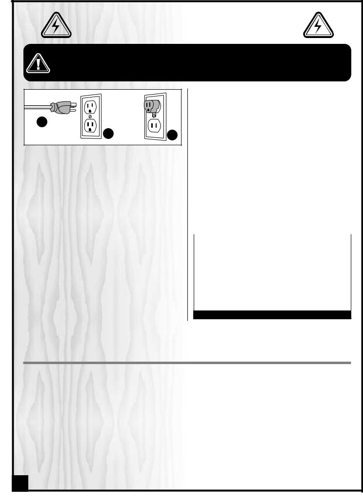
GROUNDING INSTRUCTIONS
In the event of an electrical malfunction or short circuit, grounding reduces the risk of electric shock. Though equipped with a 220V 3 phase motor, due to the electronic frequency inverter this machine is wired for 110V single phase operation and is equipped with a 3-con- ductor cord and a 3-prong grounding plug A to fit a grounded type receptacle B. Do not remove the 3rd prong (grounding pin) to make it fit into an old 2-hole wall socket or extension cord. If an adaptor plug is used, it must be attached to the metal screw of the receptacle C.
Note: The use of an adaptor plug is illegal in some areas. Check your local codes. If you have any doubts or if the supplied plug does not correspond to your electrical outlet, consult a qualified electrician before proceeding.
CIRCUIT CAPACITY
Make sure that the wires in your circuit are capable of handling the amperage draw from your machine, as well as any other machines that could be operating on the same circuit. If you are unsure, consult a qualified electrician. If the circuit breaker trips or the fuse blows regularly, your machine may be operating on a circuit
BASIC FUNCTIONS
that is close to its amperage draw capacity. However, if an unusual amperage draw does not exist and a power failure still occurs, contact a qualified technician
or our service department.
EXTENSION CORDS
If you find it necessary to use an extension cord with your machine, use only 3-wire extension cords that have 3- prong grounding plug and a matching 3-pole receptacle that accepts the tool’s plug. Repair or replace a damaged extension cord or plug immediately.
Make sure the cord rating is suitable for the amperage listed on the motor I.D. plate. An undersized cord will cause a drop in line voltage resulting in loss of power and overheating. The accompanying chart shows the correct size extension cord to be used based on cord length and motor I.D. plate amp rating. If in doubt, use the next heavier gauge. The smaller the number, the heavier the gauge.
|
|
|
|
|
AMPERES |
EXTENSION CORD LENGTH |
|||
(AMPS) |
25 FEET |
50 FEET |
100 FEET |
150 FEET |
|
|
|
|
|
< 5 |
18 |
16 |
16 |
14 |
6 TO 10 |
18 |
16 |
14 |
12 |
10 TO 12 |
16 |
16 |
14 |
12 |
12 TO 16 |
14 |
12 |
* NR |
* NR |
|
|
|
|
|
* NR = Not Recommended
This General International model 25-650ABC M1 Wood Lathe is designed specifically for medium to larger sized wood turning projects. With a maximum swing over bed of 16”, a distance between centers of 42”, and 3 electronically controlled variable speed ranges (45-1000, 85-2000 and 150 -3750 RPM) with digital spindle speed display,the 25-650ABC M1 is ideal for turnings such as chair or table legs and columns, as well as bowls of various sizes. A simple belt re-positioning on the drive pulleys, allows the operator to select the desired speed range and the electronic speed controller allows for further fine-tuning within each speed range.
With its pivoting head, larger bowls can also be turned on the outboard side of the lathe. For longer turnings an optional 18” bed extension, #25-618 can be added.
The 25-650ABC M1 comes equipped with a selection of the most commonly used accessories, including a 6” face plate for bowl turning and both live and spur center for typical spindle turning, to allow the user to begin turning (turning tools not supplied) after a few minutes of assembly and set-up, right out of the box.
The 25-650ABC M1 is designed to be compatible with all aftermarket turning accessories using MT#2 Morse taper in both headstock and tailstock and the headstock spindle threads are compatible with all 1-1/4” dia x 8 TPI female threaded chucks and face plates.
6

|
16" X 42" WOOD TURNING LATHE |
|
|
|||
|
25-650ABC M1 |
|
|
|
|
|
IDENTIFICATION OF MAIN PARTS AND COMPONENTS |
|
|||||
|
|
|
U |
|
|
|
|
|
|
T |
V |
W |
|
|
|
|
|
|||
|
|
|
|
|
||
|
|
|
X |
|
|
|
|
HEADSTOCK |
|
|
|
|
|
|
C |
|
|
|
|
|
B |
|
|
|
|
|
|
A |
D |
|
|
|
|
|
|
E |
A- MOTOR |
N- TOOL REST |
|||
|
B- HEADSTOCK |
O- TOOL REST |
||||
|
|
|||||
|
|
C- BELT TENSION |
SWIVEL ARM |
|||
|
|
P- TOOL REST SWIVEL |
||||
M |
|
|
RELEASE LEVER |
|||
F |
D- INDEXING PIN |
ARM LOCKING |
||||
|
||||||
|
G |
E- |
SPUR CENTER |
LEVER |
|
|
|
Q- TOOL REST |
|||||
|
|
F- |
FACE PLATE |
|||
K |
H |
CARRIAGE LEVER |
||||
|
G- SPINDLE SPEED |
R- TOOL REST |
||||
L |
I |
|
READ OUT |
CARRIAGE |
||
J |
H- VARIABLE SPEED |
S- TOOL REST |
||||
|
|
|||||
|
TOOL REST |
|
CONTROL KNOB |
LOCKING LEVER |
||
|
I- |
HEADSTOCK PIVOT |
||||
|
O |
T- LIVE CENTER |
||||
|
|
LOCKING PIN |
U- QUILL |
|
||
|
|
J- FORWARD / |
|
|||
|
P |
V- TAILSTOCK |
||||
|
|
REVERSE SWITCH |
||||
|
Q |
K- ON/OFF SWITCH |
W- QUILL MOVEMENT |
|||
|
|
|||||
N |
|
HANDWHEEL |
||||
|
L- |
HEADSTOCK |
||||
|
|
X- MOVABLE SWITCH |
||||
|
|
|
LOCKING LEVER |
|||
S |
|
|
|
|
||
|
M- FLYWHEEL |
|
|
|||
|
|
|
|
|||
|
R |
|
|
|
|
|
|
|
|
|
|
7 |
|
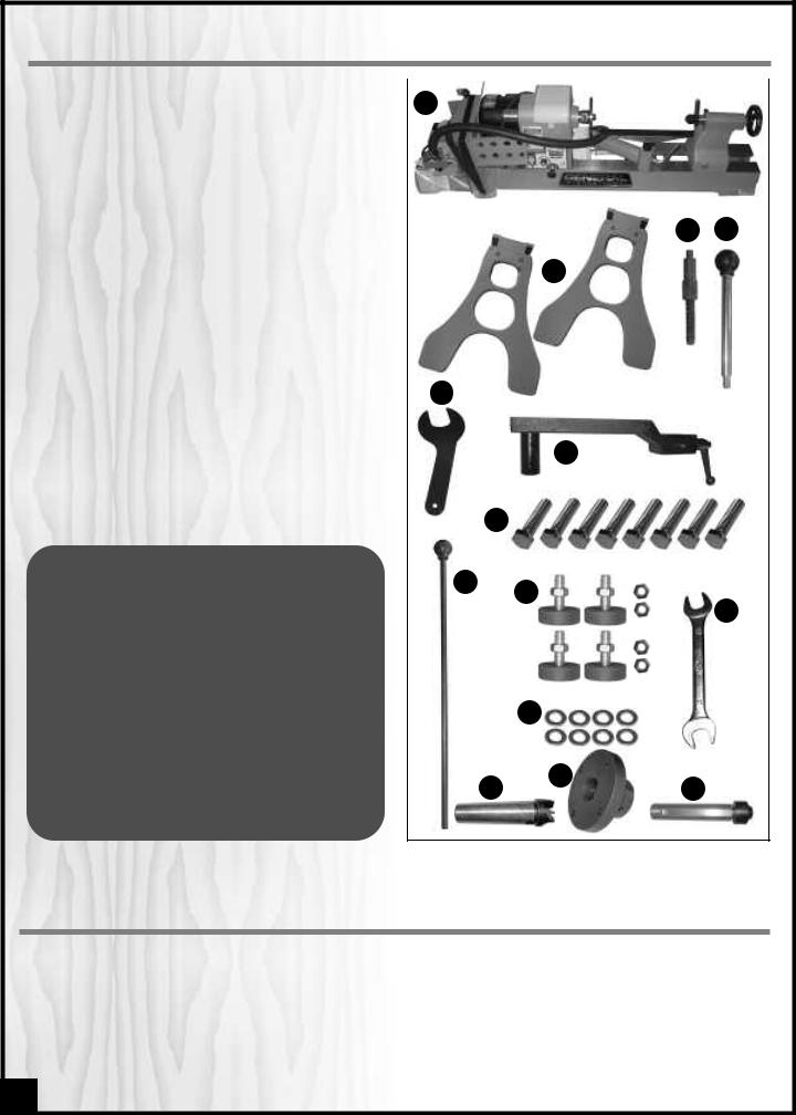
UNPACKING
Carefully unpack and remove the lathe components |
|
A |
|
|
|
||||||||
from the box and check for damaged or missing items |
|
|
|
|
|||||||||
as per the list of contents below. |
|
|
|
|
|
|
|
|
|
|
|
||
NOTE: Please report any damaged or missing items to your |
|
|
|
|
|
|
|
|
|
||||
General International distributor immediately. |
|
|
|
|
|
|
|
|
|
|
|
||
LIST OF CONTENTS |
|
QTY |
|
|
|
|
|
C |
|
D |
|||
A - |
WOOD LATHE |
1 |
|
|
|
|
|
||||||
|
|
|
|
|
|
|
|
|
|||||
|
|
|
|
|
|
|
|
|
|||||
B - |
STAND CABINET . . . . . . . . . . . . . . . . . . . . . . . . . . . . . . . |
. .2 |
|
|
|
B |
|
|
|
|
|
||
C - |
SPINDLE LOCK PIN . . . . . . . . . . . . . . . . . . . . . . . . . . . . . |
. .1 |
|
|
|
|
|
|
|
|
|
||
D - |
BELT TENSION RELEASE LEVER . . . . . . . . . . . . . . . . . . . . |
. .1 |
|
|
|
|
|
|
|
|
|
||
E - |
FACE PLATE WRENCH . . . . . . . . . . . . . . . . . . . . . . . . . . |
. .1 |
|
|
|
|
|
|
|
|
|
||
F - |
TOOL REST SWIVEL ARM . . . . . . . . . . . . . . . . . . . . . . . . |
. .1 |
|
|
|
|
|
|
|
|
|
||
G - |
. . . . . . . . . . . . . . . . . . . . . . . . . . . . . . .HEX HEAD BOLT |
. .8 |
|
|
|
|
|
|
|
|
|
||
H- |
KNOCK OUT BAR . . . . . . . . . . . . . . . . . . . . . . . . . . . . . . |
. .1 |
|
|
|
|
|
|
|
|
|
||
I - |
LEVELING FOOT W/NUT & JAM NUT |
4 |
|
E |
|
|
|
|
|||||
|
|
|
|
||||||||||
J - |
. . . . . . . . . . . . . . . . . . . . . . . . . . . . . . . . .FLAT WASHER |
. .8 |
|
|
|
|
|
|
|
|
|
||
|
|
|
|
|
|
|
|
|
|||||
K - |
12 /14 MM OPEN END WRENCH . . . . . . . . . . . . . . . . . |
. .1 |
|
|
|
|
|
|
|
|
|
||
L - |
SPUR CENTER* . . . . . . . . . . . . . . . . . . . . . . . . . . . . . . . . |
. .1 |
|
|
|
F |
|
|
|
||||
M - |
FACE PLATE* |
1 |
|
|
|
|
|
|
|||||
|
|
|
|
|
|
|
|
|
|||||
N - |
LIVE CENTER* . . . . . . . . . . . . . . . . . . . . . . . . . . . . . . . . . |
. .1 |
|
|
|
|
|
|
|
|
|
||
*Already installed on the lathe. |
|
|
|
|
|
|
|
|
|
|
|
||
|
|
|
|
G |
|
|
|
||||||
|
|
|
|
|
|
|
|
|
|
||||
ADDITIONAL REQUIREMENTS FOR SET UP
• Help of 2 extra people |
H |
|
|
|
|
||||
I |
|
|
||
• Phillips screwdriver |
|
|
|
K |
|
|
|
||
• 14 mm socket wrench (optional)
• 12 mm socket wrench (optional)
• 6 mm Allen key
J
x2
M
L N
CLEAN UP
The unpainted cast-iron surface of the lathe bed is covered with a protective coating that helps prevent rust from forming during shipping and storage. Remove this protective coating by rubbing with a rag dipped in kerosene, mineral spirits or paint thinner. (Handle and dispose of potentially flammable solvent soaked rags according to manufacturers’ safety recommendations.) Avoid rubbing the lathes painted surfaces as many solvent based products will remove paint.
To prevent rust, apply a light coating of paste wax or use regular applications of any after-market surface protectant or rust inhibitor.
8
 Loading...