


SETUP & OPERATION MANUAL |
|
Like our Canadian made design, the head |
HEAVY-DUTY 15” DRILL PRESS |
FEATURES |
6 Speed / Variable Speed |
ing the operator the flexibility to choose |
|
can be raised or lower on the column giv- |
|
the most comfortable and practical posi- |
|
tion to suit their specific work style. Equally |
|
well suited for wheelchair users or the |
|
standing operator. |
|
Variable speed handwheel adjustment |
|
sets the speeds (34-156V) and the cover |
|
opening is designed for quick and easy |
|
speed changes (34-156 only). |
|
Precision-machined high-grade cast-iron- |
|
base, table and head to ensure maximum |
|
tolerances and vibration free perform- |
|
ance. |
|
Precision machined steel column for |
|
smooth table and head adjustments. |
|
Large front-mounted paddle style stop- |
|
switch. |
|
Extra long 6” quill stroke and heavy-duty- |
|
positive depth stop. |
|
Industrial quality 1 HP motor. |
|
Smooth rack and pinion table height |
|
adjustment, designed to withstand continu- |
|
ous movement without binding. |
|
SPECIFICATIONS |
|
|
SWING 15” |
|
|
(381 MM) |
|
|
DRILLING CAPACITY 5/8” |
|
|
(16 MM) |
|
|
SPINDLE TRAVEL (STROKE) |
|
|
6” (152 MM) |
|
|
QUILL DIAMETER |
|
|
2 ?” (57 MM) |
|
|
SPINDLE DISTANCE TO TABLE |
|
|
27 1⁄2” (700 MM) |
|
|
SPINDLE DISTANCE TO BASE |
|
|
46 1⁄2” (1180 MM) |
|
|
TABLE SIZE |
|
|
14” X 17 7/8” (355 X 455 MM) |
|
|
TABLE SLOTS (2) |
|
|
9/16” (14 MM) |
MODELS |
|
34-156: (6) 400 - 5000 RPM |
||
COLUMN DIAMETER |
|
|
3” (76 MM) |
|
|
SPINDLE SPEEDS |
#34-156 |
|
JT3 |
|
|
34-156V: (VARIABLE) 400 - 5000 RPM |
|
|
SPINDLE TAPER |
|
|
OVERALL HEIGHT |
#34-156V |
|
34-156: 70 7/8”(1800MM) |
|
|
34-156V: 71 1/2”(1815MM) |
|
|
BASE SIZE |
|
|
14 3/8” X 20 3⁄4” (365 MM X 530 MM) |
|
|
MOTOR |
|
|
1 HP, 110 V, 13 A |
|
|
WEIGHT |
VERSION 2_REVISION 1 - MARCH 04/13 (S/N 34009213) |
|
320 LBS (145 KG) |
|
|
|
© Copyright General® International 03/2013 |
|

GENERAL® INTERNATIONAL
8360 Champ-d’Eau, Montreal (Quebec) Canada H1P 1Y3 Telephone (514) 326-1161 • Fax (514) 326-5555 • www.general.ca
THANK YOU for choosing this General® International model 34-156 / 34-156V Heavy-duty 15” drill press. This drill press has been carefully tested and inspected before shipment and if properly used and maintained, will provide you with years of reliable service. For your safety,as well as to ensure optimum performance and trouble-free operation, and to get the most from your investment, please take the time to read this manual before assembling, installing and operating the unit.
The manual’s purpose is to familiarize you with the safe operation, basic function, and features of this drill press as well as the set-up, maintenance and identification of its parts and components. This manual is not intended as a substitute for formal woodworking instruction, nor to offer the user instruction in the craft of woodworking. If you are not sure about the safety of performing a certain operation or procedure, do not proceed until you can confirm, from knowledgeable and qualified sources, that it is safe to do so.
Once you’ve read through these instructions, keep this manual handy for future reference.
Disclaimer: The information and specifications in this manual pertain to the unit as it was supplied from the factory at the time of printing. Because we are committed to making constant improvements, General® International reserves the right to make changes to components, parts or features of this unit as deemed necessary,without prior notice and without obligation to install any such changes on previously delivered units. Reasonable care is taken at the factory to ensure that the specifications and information in this manual corres-
ponds with that of the unit with which it was supplied. However, special orders and “after factory” modifications may render some or all information in this manual inapplicable to your machine. Further, as several generations of this model of drill press and several versions of this manual may be in circulation, if you own an earlier or later version of this unit, this manual may not depict your machine exactly. If you have any doubts or questions contact your retailer or our support line with the model and serial number of your unit for clarification.

GENERAL® & GENERAL® INTERNATIONAL WARRANTY
All component parts of General®, General® International and Excalibur by General International ® products are carefully inspected during all stages of production and each unit is thoroughly inspected upon completion of assembly.
Limited Lifetime Warranty
Because of our commitment to quality and customer satisfaction, General® and General® International agree to repair or replace any part or component which upon examination, proves to be defective in either workmanship or material to the original purchaser for the life of the tool. However,the Limited Lifetime Warranty does not cover any product used for professional or commercial production purposes nor for industrial or educational applications. Such cases are covered by our Standard 2-year Limited Warranty only.The Limited Lifetime Warranty is also subject to the “Conditions and Exceptions” as listed below.
Standard 2-Year Limited Warranty
All products not covered by our lifetime warranty including products used in commercial, industrial and educational applications are warranted for a period of 2 years (24 months) from the date of purchase. General® and General® International agree to repair or replace any part or component which upon examination, proves to be defective in either workmanship or material to the original purchaser during this 2-year warranty period, subject to the “conditions and exceptions” as listed below.
To file a Claim
To file a claim under our Standard 2-year Limited Warranty or under our Limited Lifetime Warranty, all defective parts, components or machinery must be returned freight or postage prepaid to General® International, or to a nearby distributor, repair center or other location designated by General® International. For further details call our service department at 1-888- 949-1161 or your local distributor for assistance when filing your claim.
Along with the return of the product being claimed for warranty, a copy of the original proof of purchase and a “letter of claim” must be included (a warranty claim form can also be used and can be obtained, upon request, from General® International or an authorized distributor) clearly stating the model and serial number of the unit (if applicable) and including an explanation of the complaint or presumed defect in material or workmanship.
CONDITIONS AND EXCEPTIONS:
This coverage is extended to the original purchaser only. Prior warranty registration is not required but documented proof of purchase i.e. a copy of original sales invoice or receipt showing the date and location of the purchase as well as the purchase price paid, must be provided at the time of claim.
Warranty does not include failures, breakage or defects deemed after inspection by General® or General® International to have been directly or indirectly caused by or resulting from; improper use, or lack of or improper maintenance, misuse or abuse, negligence, accidents, damage in handling or transport, or normal wear and tear of any generally considered consumable parts or components.
Repairs made without the written consent of General® Internationallwill void all warranty.

TABLE OF CONTENTS
Rules for safe operation . . . . . . . . . . . . . . . . . . . . . . . .5 Electrical requirements . . . . . . . . . . . . . . . . . . . . . . . .6
Grounding instructions . . . . . . . . . . . . . . . . . . . . . . . . . . . . . . . . . . . . . . . . .6 Circuit capacity . . . . . . . . . . . . . . . . . . . . . . . . . . . . . . . . . . . . . . . . . . . . . .6
Extension cords . . . . . . . . . . . . . . . . . . . . . . . . . . . . . . . . . . . . . . . . . . . . . . .6
Identification of main parts and components . . . . . . . . . . . . .7
Basic functions . . . . . . . . . . . . . . . . . . . . . . . . . . . . . . . . . . . . . . .8 Unpacking . . . . . . . . . . . . . . . . . . . . . . . . . . . . . . . . . . . . . . . . . . . .8 Placement within the shop . . . . . . . . . . . . . . . . . . . . . . . . . . . .9
Placement within the shop . . . . . . . . . . . . . . . . . . . . . . . . . . . . . . . . . . . . .9
Establishing a safety zone . . . . . . . . . . . . . . . . . . . . . . . . . . . . . . . . . . . . . .9
Assembly Instructions . . . . . . . . . . . . . . . . . . . . . . . . . . . . . .9-10
Install table height adjustment handle . . . . . . . . . . . . . . . . . . . . . . . . . . .9 Reposition the head . . . . . . . . . . . . . . . . . . . . . . . . . . . . . . . . . . . . . . . . . .10
Install the chuck . . . . . . . . . . . . . . . . . . . . . . . . . . . . . . . . . . . . . . . . . . . . .10
Adjustments & Controls . . . . . . . . . . . . . . . . . . . . . . . . . . . . . . .10
Connecting to a power source . . . . . . . . . . . . . . . . . . . . . . . . . . . . . . . .10 On/Off power switch . . . . . . . . . . . . . . . . . . . . . . . . . . . . . . . . . . . . . . . . . .11 Table height adjustment . . . . . . . . . . . . . . . . . . . . . . . . . . . . . . . . . . . . . .11 Table swing adjustment . . . . . . . . . . . . . . . . . . . . . . . . . . . . . . . . . . . . . . .11 Depth stop adjustment . . . . . . . . . . . . . . . . . . . . . . . . . . . . . . . . . . . . . . . .11 Changing speed (model 34-156 only) . . . . . . . . . . . . . . . . . . . . . . . . . .12
Spindle speed control (model 34-156V only) . . . . . . . . . . . . . . . . . . . . .13
Basic adjustments
Install a drill bit . . . . . . . . . . . . . . . . . . . . . . . . . . . . . . . . . . . . . . . . . . . . . .13
Maintenance . . . . . . . . . . . . . . . . . . . . . . . . . . . . . . . . . . . . . . . . .13
Periodic maintenance . . . . . . . . . . . . . . . . . . . . . . . . . . . . . . . . . . . . . . . .13
Troubleshooting . . . . . . . . . . . . . . . . . . . . . . . . . . . . . . . . . . . . .14
Recommended optional accessories . . . . . . . . . . . . . . . . . .15
Diagrams & parts list . . . . . . . . . . . . . . . . . . . . . . . . . . . . . .16-25 To contact us . . . . . . . . . . . . . . . . . . . . . . . . . . . . . . . . . . . . . . . .26

RULES FOR SAFE OPERATION
To help ensure safe operation, please take a moment to learn the machine’s applications and limitations, as well as poten- tial hazards. General® International disclaims any real or implied warranty and holds itself harmless for any injury that may result from improper use of its equipment.
1.Do not operate the drill press when tired, distracted, or under the effects of drugs, alcohol or any medication that impairs reflexes or alertness.
2.The working area should be well lit, clean and free of debris.
3.Keep children and visitors at a safe distance when the drill press is in operation; do not permit them to operate the drill press.
4.Childproof and tamper proof your shop and all machinery with locks, master electrical switches and switch keys, to prevent unauthorized or unsupervised use.
5.Stay alert! Give your work your undivided attention. Even a momentary distraction can lead to serious injury.
6.Fine particulate dust is a carcinogen that can be hazardous to health. Work in a well-ventilated area and whenever possible use a dust collector and wear eye, ear and respiratory protection devices.
7.Do not wear loose clothing, gloves, bracelets, necklaces or other jewelry while the drill press is in operation.
8.Be sure that adjusting wrenches, tools, drinks and other clutter are removed from the machine and/or the table surface before operating.
9.Keep hands well away from the drill bit and all moving parts. Use a hold-down or clamp to secure the stock, and use a brush, not hands, to clear away chips and dust.
10.Be sure that the drill bit is securely installed in the chuck before operation.
11.Be sure the drill bit has gained full operating speed before beginning to drill.
12.Always use a clean, properly sharpened bit. Dirty or dull bits are unsafe and can lead to accidents.
13.Use suitable work piece support if the work piece does not have a flat surface.
14.Do not push or force the bit into the stock. The drill will perform better and more safely when working at the rate feed for which it was designed.
15.Avoid working from awkward or off balance positions. Do not overreach and keep both feet on floor.
16.Keep guards in place and in working order. If a guard must be removed for maintenance or cleaning be sure it is properly re-attached before using the tool again.
17.Never leave the machine unattended while it is running or with the power on.
18.Use of parts and accessories NOT recommended by GENERAL® INTERNATIONAL may result in equipment malfunction or risk of injury.
19.Never stand on machinery. Serious injury could result if the tool is tipped over or if the drill bit is unintentionally contacted.
20.Always disconnect the tool from the power source before servicing or changing accessories such as bits, or before performing any maintenance, cleaning, or if the machine will be left unattended.
21.Make sure that the switch is in the “OFF” position before plugging in the power cord.
22.Make sure the tool is properly grounded. If equipped with a 3-prong plug, it should be used with a threepole receptacle. Never remove the third prong.
23.Do not use this drill press for any purpose other than its intended use. If used for other purposes, GENERAL® INTERNATIONAL disclaims any real or implied warranty and holds itself harmless for any injury, which may result from that use.
5
ELECTRICAL REQUIREMENTS
BEFORE CONNECTING THE MACHINE TO THE POWER SOURCE, VERIFY THAT THE VOLTAGE OF YOUR POWER SUPPLY CORRESPONDS WITH THE VOLTAGE SPECIFIED ON THE MOTOR I.D. NAMEPLATE. A POWER SOURCE WITH GREATER VOLTAGE THAN NEEDED CAN RESULT IN SERIOUS INJURY TO THE USER AS WELL AS DAMAGE TO THE MACHINE. IF IN DOUBT, CONTACT A QUALIFIED ELECTRICIAN BEFORE CONNECTING TO THE POWER SOURCE.
THIS TOOL IS FOR INDOOR USE ONLY. DO NOT EXPOSE TO RAIN OR USE IN WET OR DAMP LOCATIONS.
a
b c
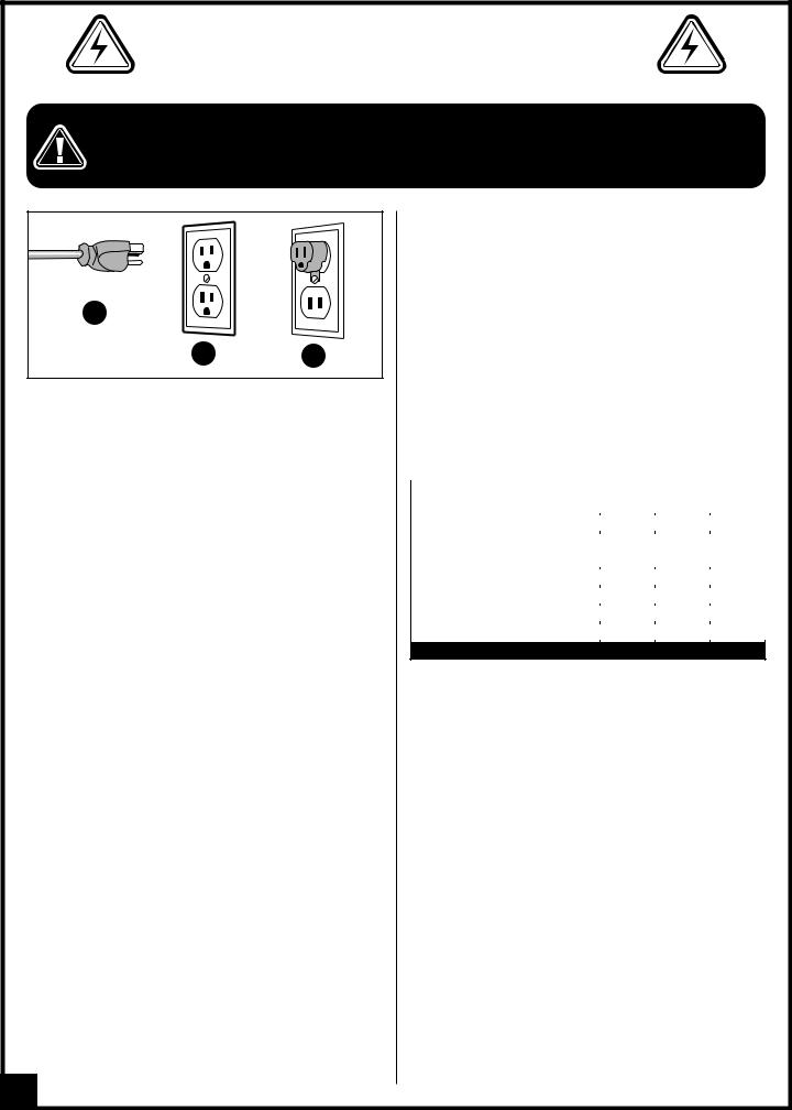
GROUNDING INSTRUCTIONS
In the event of an electrical malfunction or short circuit, grounding reduces the risk of electric shock. The motor of this machine is wired for 110V single phase operation and is equipped with aa 3-conductor cord and a 3- prong bgrounding plug  to fit a grounded type receptacle
  . Do not remove the 3rd prong (grounding pin) to make it fit into an old 2-hole wallc socket or extension cord. If an adaptor plug is used
 , it must be attached to the metal screw of the receptacle.
Note: The use of an adaptor plug is illegal in some areas. Check your local codes. If you have any doubts or if the supplied plug does not correspond to your electrical outlet, consult a qualified eletrician before proceeding.
CIRCUIT CAPACITY
Make sure that the wires in your circuit are capable of handling the amperage draw from your machine, as well as any other machines that could be operating on the same circuit. If you are unsure, consult a qualified electrician. If the circuit breaker trips or the fuse blows regularly, your machine may be operating on a circuit that is close to its amperage draw capacity. However,if an unusual amperage draw does not exist and a power failure still occurs, contact a qualified technician or our service department.
EXTENSION CORDS
If you find it necessary to use an extension cord with your machine, use only 3-wire extension cords that have 3- prong grounding plug and a matching 3-pole receptacle that accepts the tool’s plug. Repair or replace a damaged extension cord or plug immediately.
Make sure the cord rating is suitable for the amperage listed on the motor I.D. plate. An undersized cord will cause a drop in line voltage resulting in loss of power and overheating. The accompanying chart shows the correct size extension cord to be used based on cord length and motor I.D. plate amp rating. If in doubt, use the next heavier gauge. The smaller the number, the heavier the gauge.
|
|
|
|
|
|
TABLE - MINIMUM GAUGE FOR CORD |
|
||||
|
|
TOTAL LENGTH OF CORD IN FEET |
|
||
AMPERE |
110 VOLTS |
25 FEET |
50 FEET |
100 FEET |
150 FEET |
RATING |
|
|
AWG |
|
|
|
|
|
|
|
|
|
|
|
|
|
|
< 5 |
-------> |
18 |
16 |
16 |
14 |
6 À 10 |
-------> |
18 |
16 |
14 |
12 |
10 À 12 |
-------> |
16 |
16 |
14 |
12 |
12 À 16 |
-------> |
14 |
12 |
* NR |
* NR |
* NR = Not Recommended
6
|
HEAVY-DUTY 15” DRILL PRESS |
||
|
34-156 / 34-156V |
|
|
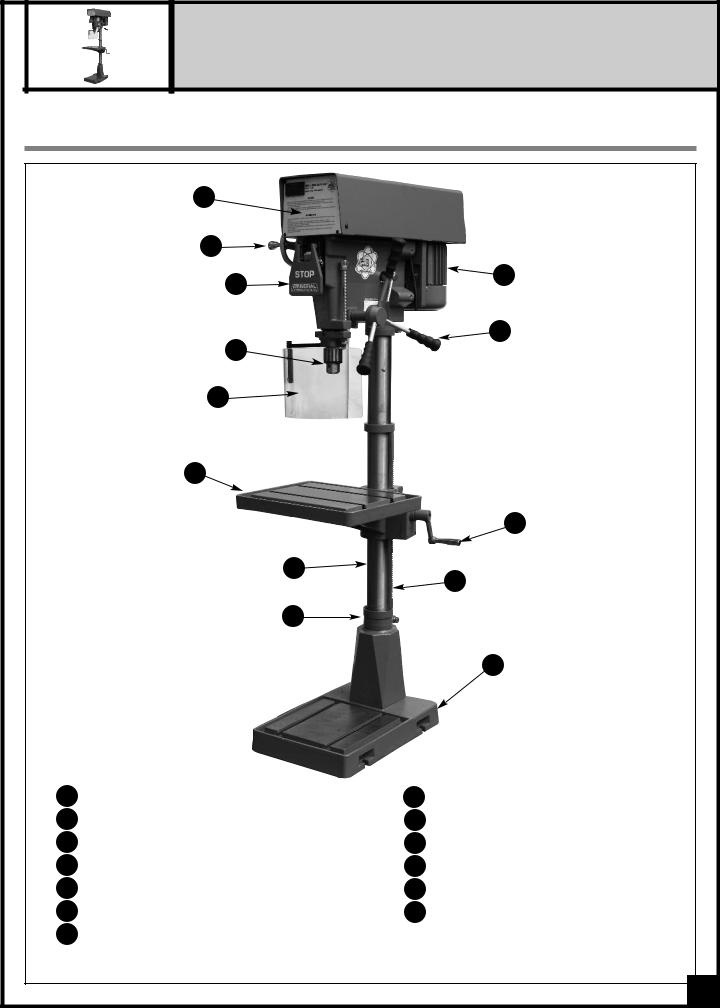
IDENTIFICATION OF MAIN PARTS AND COMPONENTS |
|||
|
A |
|
|
|
B * |
|
|
|
C |
|
I |
|
|
|
|
|
|
|
J |
|
D |
|
|
|
E |
|
|
|
F |
|
|
|
|
|
K |
|
G |
|
L |
|
|
|
|
|
H |
|
|
|
|
|
M |
A PULLEY CASE COVER |
H |
COLUMN FLANGE |
|
B |
SPINDLE SPEED CONTROL* |
I |
MOTOR |
C ON/OFF SWITCH |
J |
DOWN FEED HANDLE |
|
D |
CHUCK |
K |
TABLE HEIGHT ADJUSTMENT HANDLE |
E |
CHUCK GUARD |
L |
RACK |
F |
TABLE |
M |
BASE |
G COLUMN |
|
|
|
* Model 34-156V only. |
|
|
|
|
|
|
7 |
BASIC FUNCTIONS
Featuring a large front mounted stop switch, the 34-156/156V M1 also offers the user the flexibility to choose from 6 spindle speed options (34-156) or mechanical variable speed (34-156V) to suit a large variety of drilling applications.
For model 34-156 by simply changing the positioning of the belts on the pulleys, which is clearly shown on the conveniently located speed selection chart located on the inside of the pulley cover door, the user can select the following spindle speeds: 400, 625, 1125, 1950, 3400 & 5000 RPM. For model 34-156V a large side mounted handwheel allows the user to dial-in the desired spindle speed anywhere from 400-5000 rpm, with a digital display showing the speed selected.
As a general rule, drilling larger holes or drilling in metals is best done at lower speeds. Drilling at higher spindle
speeds is normally reserved for smaller holes or drilling in wood.
UNPACKING
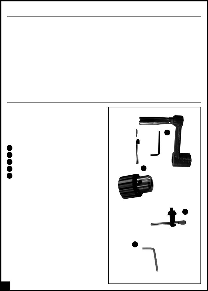
Carefully unpack and remove the drill press and its components from its packaging and check for damaged or missing items as per the list of contents below.
NOTE: Please report any damaged or missing items to your General International distributor immediately.
LIST OF CONTENTS |
QTY |
|
B |
|
|
|
|
|
|
A |
DRILL PRESS (NOT SHOWN) . . . . . . . . . . . . . . . . . . . |
. .1 |
|
|
B |
TABLE HEIGHT ADJUSTMENT HANDLE . . . . . . . . . . . . |
.1 |
|
|
C |
CHUCK . . . . . . . . . . . . . . . . . . . . . . . . . . . . . . . . . . . . |
.1 |
|
|
|
|
|
|
|
D |
CHUCK KEY . . . . . . . . . . . . . . . . . . . . . . . . . . . . . . . . |
.1 |
C |
|
E |
4 MM ALLEN KEY . . . . . . . . . . . . . . . . . . . . . . . . . . . . |
.1 |
|
|
E
8
 Loading...