


 Heavy-duty one-piece frame, designed for added stability, requires no further assembly.
 Precision-balanced, rubber laminated, cast-iron wheels, mounted on two heavy-duty ball bearings.
 Large, ribbed cast-iron table with heavyduty one-piece trunnion for 0 - 45° tilting, for bevel cuts.
 Convenient blade tension adjustment hand wheel.
 A tension scale allows the operator to adjust the tension for different blade widths.
 Foot brake for quick blade stoppage after machine shut-off.
 4” dust collection port for easy hookup to a dust collector.
 Powerful totally enclosed fan cooled (T.E.F.C.)industrial motor.
 Magnetic safety switch with emergency stop button for added safety.
 Tri-Axis bearing guides.
WHEEL SIZE 18” (450 MM)
WHEEL SPEED 980 RPM - #90-270
1010 RPM - #90-270 HD
WIDTH OF WHEEL
1 1⁄8” (28.5 MM)
MIN/MAX BLADE WIDTH 1⁄4” TO 1” (6.3 TO 25.4 MM)
BLADE LENGTH
153” (3886 MM) - #90-270
168 1⁄2” (4280 MM) - #90-270 HD
BLADE SPEED
4460 FPM (1338 MPM) - #90-270
4700 FPM (1410 MPM) - #90-270 HD
MAXIMUM DEPTH OF CUT 12” (305 MM) - #90-270 18” (457 MM) - #90-270 HD
MAXIMUM WIDTH OF CUT 17 1⁄4” (438 MM)
TABLE SIZE
24” X 19 1⁄2” (610 X 500 MM)
TABLE TILT
0° TO 45° (OUT)
TABLE HEIGHT
35 1⁄2” (902 MM)
MOTOR- #90-270
M1 - 3 HP, 220 V, 1 PH, 19 A
M2 - 3 HP, 220/440 V,3 PH, 8/4.6 A
M3 - 3 HP, 600 V, 3 PH, 2.9 A
MOTOR - #90-270HD
M1 - 5 HP, 220 V, 1 PH, 23 A
M2 - 5 HP, 220/440 V,3 PH, 13.3/7.6 A M3 - 5 HP, 600 V, 3 PH, 4.8 A
WEIGHT
616 LBS (280 KG) - #90-270
710 LBS (323 KG) - #90-270 HD
REVISION 1 - FEB 04/08
© COPYRIGHT GENERAL INTERNATIONAL 02/2008

GENERAL® INTERNATIONAL
8360 Champ-d’Eau, Montreal (Quebec) Canada H1P 1Y3
Telephone (514) 326-1161 • Fax (514) 326-5555
www.general.ca
THANK YOU for choosing this General® International model 90-270 or 90-270HD 18”Wood Cutting Bandsaw.This machine has been carefully tested and inspected before shipment and if properly used and maintained, will provide you with years of reliable service. To ensure optimum performance and trouble-free operation, and to get the most from your investment, please take the time to read this manual before assembling, installing and operating the unit.
The manual’s purpose is to familiarize you with the safe operation, basic function, and features of this wood cutting bandsaw as well as the set-up, maintenance and identification of its parts and components. This manual is not intended as a substitute for formal woodworking instruction, nor to offer the user instruction in the craft of woodworking. If you are not sure about the safety of performing a certain operation or procedure, do not proceed until you can confirm, from knowledgeable and qualified sources, that it is safe to do so.
Once you’ve read through these instructions, keep this manual handy for future reference.
GENERAL ® INTERNATIONAL WARRANTY
All component parts of General® International machinery are carefully tested and inspected during all stages of production, and each machine is thoroughly inspected upon completion of assembly. Because of our commitment to quality and customer satisfaction, General® International agrees to repair or replace, within a period of 24 months from date of purchase, any genuine part or parts which, upon examination, prove to be defective in workmanship or material. In order to obtain this warranty, all defective parts must be returned freight pre-paid to General® International Mfg. Co., Ltd. Repairs attempted without our written authorization will void this warranty.
Disclaimer: The information and specifications in this manual pertain to the unit as it was supplied from the factory at the time of printing. Because we are committed to making constant improvements, General® International reserves the right to make changes to components, parts or features of this unit as deemed necessary, without prior notice and without obligation to install any such changes on previously delivered units. Reasonable care is taken at the factory to ensure that the specifications and information in this manual corresponds with that of the unit with which it was supplied. However,special orders and “after
factory” modifications may render some or all information in this manual inapplicable to your machine. Further, as several generations of this bandsaw and several versions of this manual may be in circulation, if you own an earlier or later version of this unit, this manual may not depict your machine exactly. If you have any doubts or questions contact your retailer or our support line with the model and serial number of your unit for clarification.

Rules for Safe Oper ation
To help ensure safe operation, please take a moment to learn the machine’s applications and limitations, as well as potential hazards. General® International disclaims any real or implied warranty and hold itself harmless for any injury that may result from the improper use of it’s equipment.
1.Do not operate the bandsaw when tired, distracted or under the effects of drugs, alcohol or any medication that impairs reflexes or alertness.
2.The working area should be well lit, clean and free of debris.
3.Keep children and visitors at a safe distance when the sander is in operation; do not permit them to operate the sander.
4.Childproof and tamper proof your shop and all machinery with locks, master electrical switches and switch keys, to prevent unauthorized or unsupervised use.
5.Stay alert! Give your work your undivided attention. Even a momentary distraction can lead to serious injury.
6.Fine particulate dust is a carcinogen that can be hazardous to health. Work in a well-ventilated area and whenever possible use a dust collector. Wear face, eye, ear, respiratory and body protection devices.
7.Do not wear loose clothing, gloves, bracelets, necklaces or other jewelry while the bandsaw is in operation.
8.Be sure that adjusting wrenches, tools, drinks and other clutter are removed from the machine and/or the table surface before operating.
9.Keep hands well away from the blade and all moving parts. Use a brush, not hands, to clear away chips and dust.
10.Adjust and position upper and lower blade guides before starting to cut. Upper blade guide should be adjusted to approximately 1/8” above the material to be cut.
11.Adjust blade tension and tracking before starting to cut.
12.Saw teeth must point down toward the table.
13.Be sure that the blade has gained full operating speed before starting to cut.
14.Always use a clean, properly sharpened blade. Dirty or dull blades are unsafe and can lead to accidents.
15.Use suitable work piece support if the work piece does not have a flat surface.
16.Hold material firmly against the table.
17.Do not work on long stock without adequate support on the out feed end of the table.
18.If using a power feeder,stop the feeder before stopping the bandsaw.
19.Do not push or force stock into the blade. The bandsaw will perform better and more safely when working at the rate for which it was designed.
20.Avoid working from awkward or off balance positions. Do not overreach and keep both feet on floor.
21.Keep guards in place and in working order. If a guard must be removed for maintenance or cleaning be sure it is properly re-attached before using the tool again.
22.Never leave the machine unattended while it is running or with the power on.
23.Use of parts and accessories NOT recommended by General® International may result in equipment malfunction or risk of injury.
24.Never stand on machinery. Serious injury could result if the tool is tipped over or if the cutting tool is unintentionally contacted.
25.Always disconnect the machine from the power source before servicing or changing accessories such as blades, or before performing any maintenance or cleaning, or if the machine will be left unattended.
26.Make sure that the switch is in the “OFF” position before plugging in the power cord.
27.Make sure the tool is properly grounded. If equipped with a 3 - prong plug it should be used with a three-pole receptacle. Never remove the third prong.
28.Do not use this bandsaw for other than its intended use. If used for other purposes, General® International disclaims any real implied warranty and holds itself harmless for any injury, which may result from that use.

ELECTRICAL REQUIREMENTS
NOTE: VOLTAGE REQUIREMENTS AND AMPERAGE DRAW FOR M2 & M3 3-PHASE MOTORS MAY NOT BE FULLY DESCRIBED IN THIS MANUAL. FOR COMPLETE ELECTRICAL REQUIREMENTS REFER TO THE MOTOR I.D. NAME PLATE ON THE MACHINE. IF IN DOUBT CONSULT A LICENSED QUALIFIED ELECTRICIAN BEFORE PROCEEDING.
Before connecting the machine to the power source, verify that the voltage of your power supply corresponds with the voltage specified on the I.D. nameplate located on the back of the machine. A power source with greater volt - age than needed can result in serious injury to the user as well as damage to the machine. If in doubt, contact a qualified electrician before connecting to the power source.
This tool is for indoor use only. Do not expose to rain or use in wet or damp locations.
ELECTRICAL CONNECTIONS
Both a manual circuit breaker (or similar device) as well as an ele ctrical plug are recommended and should be installed by a qualified electrician. Use l ocally appr oved wir e  that includes a separate grounding wire , and a 3 prong grounding type plug
  with a matching receptacle
  . (Fig. 1)
GROUNDING INSTRUCTIONS
In the eve nt of an e lectrical malfunction o r sho rt c ircuit, grounding reduces the risk of electric shock to the operator. The motor of the “M1” model of this machine is wired for 220V single phase operation. As with
many stationary industrial type machines, because each installati on situation is u nique, this bandsaw is supplied without a power cord or plug. The installation of an appropriate power cord and plug must be performed by a qualified electrician. The machine must beconnected
to an electrical source using a power cord that has a grounding wire, which must also be properly connected to the grounding prong on the plug. The outlet must be properly installed and grounded and all electrical connections must be made in accordance with all local codes and regulations.
CIRCUIT CAPACITY
Make sure that the wires in your circuit are capable of handling the amperage draw from your machine, as well as any other machines that could be operating on the same circuit. If you are unsure, consult a qualified electrician. If the circuit breaker trips or the fuse blows regularly, your machine may be operating on a circuit that is close to its amperage draw capacity. However, if an unusual amperage draw does not exist and a power failure still occurs, contact a qualified technician or our service department.
EXTENSION CORDS
The use of an extension cord is not generally recommended for 220V equipment. If you find it necessary, use only 3-wire extension cords that have 3-prong grounding plug and a matching 3-pole receptacle that accepts the tool’s plug. Repair or replace a damaged extension cord or plug immediately.
If you find it necessary to u se an extens ion cord with your machine make sure the cord rating is suitable for the amperage listed on the motor I.D. plate. An undersized co rd will cause a drop in line voltage resulting in loss of power and overheating. The accompanying chart shows the correct size extension cord to be used based on cord
length and motor I.D. plate amp rating. If in doubt, use the next heavier gauge. The smaller the number, the heavier |
||||||||||
the gauge. |
|
|
|
|
|
|
|
|||
|
|
|
|
|
|
|
|
|
|
|
|
|
|
|
|
|
TABLE - MINIMUM GAUGE FOR CORD |
|
|
||
|
|
|
|
|
|
|
|
|
|
|
|
|
AMPERE |
VOLTS |
|
TOTAL LENGTH OF CORD IN FEET |
|
||||
|
|
RATING |
110 V |
25 ft. |
50 ft. |
|
100 ft. |
150 ft. |
||
|
|
MORE |
NOT |
220 V |
50 ft. |
100 ft. |
|
200 ft. |
300 ft. |
|
|
|
THAN |
MORE |
|
|
|
|
|
|
|
|
|
THAN |
|
|
|
AWG |
|
|
||
|
|
|
|
|
|
|
|
|||
|
0 |
6 |
|
|
18 |
16 |
|
16 |
14 |
|
|
|
|
|
|||||||
|
6 |
10 |
|
|
18 |
16 |
|
14 |
12 |
|
|
|
|
|
|||||||
|
10 |
12 |
|
|
16 |
16 |
|
14 |
12 |
|
|
|
|
|
|||||||
|
|
12 |
16 |
|
|
14 |
12 |
|
- |
- |
|
|
|
|
|||||||
4

18” WOOD CUTTING BANDSAW |
|
90-270 or 90-270HD |
|
IDENTIFICATION OF MAIN PARTS AND COMPONENTS |
|
FRONT VIEW |
REAR VIEW |
UPPER WHEEL |
|
TENSION ADJUSTMENT HAND WHEEL |
|
FENCE |
|
LOWER WHEEL |
BLADE GUARD LOCK KNOB |
UPPER BLADE GUIDES AND SUPPORT |
BLADE GUARD ADJUSTMENT |
BEARING ASSEMBLY |
HAND WHEEL |
BLADE GUARD |
TRACKING ADJUSTMENT KNOB |
DUST CHUTE |
SWITCH BOX |
FOOT BRAKE PEDAL |
MOTOR |
ON/OFF SWITCH |
ELECTRICAL CONNECTION BOX |
BLADE TENSION INDICATOR |
TABLE TILT ANGLE INDICATOR |
|
5 |
UNPACKING
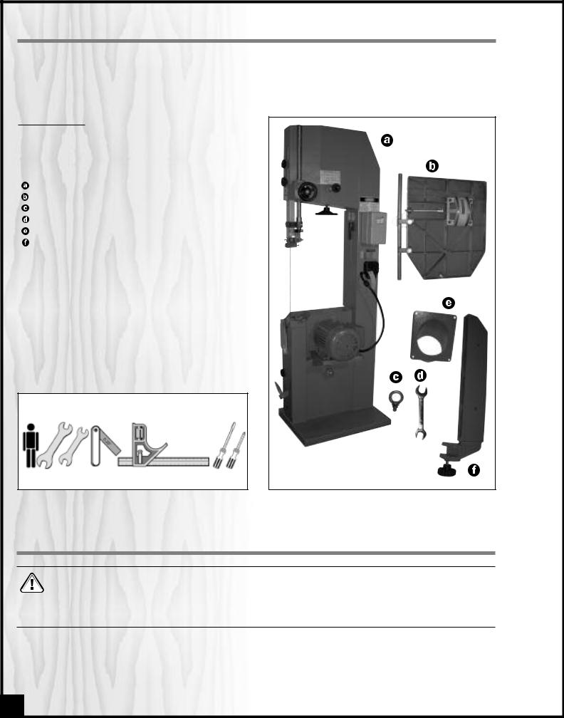
Carefully unpack and remove the unit and its compone nts from its shipping contai ner and check for missing or damaged items as per the list of contents below.
NOTE: Please report any damaged or missing items to your GENERAL® INTERNATIONAL distributor imm ediately.
LIST OF CONTENTS
Once the parts have been removed from the packaing, you should have the following items:
|
QTY |
18” WOOD CUTTING BANDSAW |
1 |
TABLE . . . . . . . . . . . . . . . . . . . . . . . . . . . . . . . . . . . |
. . .1 |
EYEBOLT . . . . . . . . . . . . . . . . . . . . . . . . . . . . . . . . . |
. . .1 |
19/21 MM COMBINATION WRENCH . . . . . . . . . . |
. . .1 |
DUST PORT . . . . . . . . . . . . . . . . . . . . . . . . . . . . . . . |
. . .1 |
RIP FENCE . . . . . . . . . . . . . . . . . . . . . . . . . . . . . . . . |
. . .1 |
ADDITIONAL REQUIREMENTS FOR SET UP
• Three extra people for help with lifting machine (or hoist or forklift with chains)
•14 mm open end wrench
•12 mm open end wrench
•Feeler gauge set
•Combination square
•Flat head Screwdriver
• Phillips Screwdriver
3
LIFTING AND HANDLING THE MACHINE
These models 90-270 and 90-270HD 18” wood cutting bandsaws are very heavy. Do not over-exert. The help of at least three assistants, a hoist or forklift with chains will be needed for the following step.
To limit the risk of serious injury or damage to the machine, any equipment used to lift this machine (hoist or fork - lift) should have a rated capacity in excess of 616 lbs (280 kg) for model 90-270 and of 671 lbs (305 kg) for model 90-270HD.
To limit t he potential for da mage in transport, this bandsaw is shipped from the factory in the horizontal position. Because of its great weight a minimum of 3 extra people will be required to assist with lifting and setting the machine upright. That being said, to limit the risk of serious injury or damage to the machine, ideally, ahoist should be used. A hoisting eyebolt is provided for that purpose. Install the eyebolt on top of the bandsaw as instructed in section “ASSEMBLY INSTRUCTIONS” on page 8.
6

PLACEMENT WITHIN THE SHOP / ESTABLISHING A SAFETY ZONE
PLACEMENT WITHIN THE SHOP |
|
|
|
Model #90-270 |
|
Model #90-270HD |
This machine should be installed and operated only on |
|
|
|
|
|
a solid, flat and stable floo r that is able to suppor t the |
|
|
|
|
|
weight of the ba ndsaw 616 lbs (280 kg) for mod el 90- |
|
|
|
|
|
270 and of 671 lbs (305 kg) for model 90-270HD and the |
|
|
|
|
|
operator. Using the dimensions shown in Fig. 2 & 2.1 as |
75” |
|
|
|
|
a guideline, plan fo r placement within your shop that |
|
82” |
|
||
|
25” |
|
|||
will a llow the operato r to wo rk unencumber ed and |
33” |
34” |
27” |
||
|
|||||
unobstructed by foot traffic (either passing shop visitors |
|
|
|
||
|
|
|
|
||
or other shop workers) or other tools or machinery. |
|
|
|
|
|
|
27” |
15” |
27” |
20” |
|
ESTABLISHING A SAFETY ZONE |
|
|
|||
|
|
|
|
||
For shops with frequent visito rs or multiple opera tors, it is |
Fig. 2 |
|
Fig. 2.1 |
|
|
advisable to e stablish a Safety Z one arou nd sh op |
|
|
|||
machinery. A c learly defined “no-go” zone on the floor |
|
|
|
|
|
around each machine can help avoid accidents that could cause injury to either the operator or the shop visitor. |
|||||
It is advisable to take a few moments to either paint (using non-slip paint) or using tape, define on the floor the lim- |
|||||
its or perimeter of each machines safety zone. Take steps to ensure that all operators and shop visitors are aware |
|||||
that these areas are off limits whenever a machine is running for everyone but the individual operating the unit. |
|||||
CLEAN UP
The protective coating on the s aw table prevents rust from forming during shipping and storage. Remove it by rubbing with a rag dipped in kerosene, mineral spirits or paint thinner. (Dispose of potentially flammable solvent-soaked rags according to manufacturer’s safety recommendations.)
A putty knife, held flat to avoid scratching the surface, may also be us ed to scrape o ff the c oating followed by clean-up with solvent. Avoid ru bbing the saw’s painted surfaces, as many solvent-based products will remove paint.
To prevent rust, apply a light coating of paste wax or use regular applications of any after-market surface protectant or rust inhibitor such as Ge neral International “Top Saver” item #GC-010.
Tip: With a screw driver, push a solvent-saturated rag into the T-slot to remove the grease.
7

ASSEMBLY INSTRUCTIONS
For your convenience this bandsaw is s hipped from the factory partially assembled and requires only minimal assembly and set up before being put into service.
Serious personal injury could occur if you connect the machine to the power source before you have completed the installation and assembly steps. DO NOT connect the machine to the power source until instructed to do so.
INSTALLING THE HOISTING EYEBOLT
1.Turnthe knob clockwise to unlock the upper wheel 2. Remove the nut
  from the provided hoisting eye-
door, then open the door. |
bolt and insert the eyebolt in the hole located on |
|
top of the bandsaw. |
3.Put the nut back and tighten firmly, using het supplied 19 mm wrench, then close and lock the upper wheel door.
PREPARING TABLE INSTALLATION
1. Remove the table tilt trunnion bolt  and flat washer
  , located on the trunnion support bracket
  and set it aside.
2.Remove the table aligning pin  from the table slot on the front of the table.
Note: The table aligning pin should be easily removable with fingers only. If it is jammed, use pliers to remove it from the table slot.
8

INSTALLING THE TABLE
This bandsaw table is heavy. Do not over-exert. The help of an assistant will be needed for the following step.
90° CW |
Note: Make sure that both table tilt trunnion grooves align in the trunnion bracket  .
.
1. Guide the gap between the rail and the edge of |
2. Put the flat washer down on the table tilt trunnion |
|
the table over the saw blade |
then rotate 90° |
then slip the table tilt trunnion bolt through the hole in |
clockwise so the slot is parallel to the blade, and |
the trunnion bracket and tighten with the 19/21 mm |
|
guide the ta ble so the bla de is at the end of the |
combination wrench provided. |
|
slot |
|
|
3. |
Re-install the table aligning pin |
in the hole |
on |
|
the front of the table. |
|
|
INSTALLING THE DUST PORT
The dust port has a 4" opening to accommodate connection to a dust collector (not included). Install the dust outlet on the right side of the band saw as follows:
1.Unscrew both wing nuts  then remove the yelow blade guard
  . Set it aside, along with the two wing nuts and two flat washers.
2.Remove the four screws  already mounted on the side panel.
9

3.Position the dust port on the side panel, its open end facing downward  , and a ttach it using the
four screws. Then , pu t t he blad e g uard back i n place  .
.
REPOSITIONNING THE FOOT BRAKE
To limit the p otential fo r da mage in transport, this bandsaw is shipped from the factory with the the foot brake pedal tilted up  . Tobe operational, the pedal must be tilted down as follows:
1. Loosen thebolt that attaches the foot brake pedal to the mounting bracket using a 14 mm open end wrench  .
.
2.Swivel the foot brake pedal manually  .
.
3.Tighten the bolt to lo ck the foot brake pedal in position.
BASIC FUNCTIONS OF THE UNIT
This 18" wood cutting bandsaw is supplied with a 1/2" wide general purpose blade and is designed to accommodate blade widths from 1/4" to 1". Ideal blade length for the model 90-270 is 153" (3886 mm) and ideal blade length for the 90-270HD is 168 1/2" (4280 mm).
Note: Generally speaking, because the upper wheel height is somewhat adjustable (to allow for blade tensioning), a blade length variation of plus or minus 1/2" from the “ideal blade length” can be accommodated on both models.
Maximum inboard width of cut (space between the blade and the body of the saw is 17 1/4 " for both models.
For cutting thicker stock or for resawing, the maximum depth of cut (or max. workpiece height is 12 " for the 90-270 and 18" for the 90-270HD.
A sturdy,cast iron, adjustable rip fence is supplied to serve as a straightedge to guide the workpiece for longer rip cuts. The fence can easily be removed and set aside when not required, for example when mak - ing curved cuts.
10
BASIC ADJUSTMENTS AND CONTROLS
CONNECTING TO A POWER SOURCE
SWITCH
OFF Contact a qualified electrician for the installation of a power plug and cord for connecting the band - saw to a power source.
To avoid risk of shock or fire do not operate the unit with a damaged power cord or plug. Replace damaged cord or plug immediately.
To avoid unexpected or unintentional start-up, make sure that the power switch on the bandsaw is in the OFF position before connecting to a power source.
Once the ins tallation of a power cord and plug has been completed, plug the power cord into an appropriate outlet. (Fig. 3) (Refer back to the section entitled “ELECTRICAL R EQUIREMENTS” on p age 4, and make sure all requirements and grounding instructions are followed).
Fig. 3
MAGNETIC SWITCH
Make sure the switch is in the “OFF” position (red button has been pressed) before plugging in the power cord.
This bandsaw is equipped with a MAGNETIC SWITCH,  , located at the front, on the frame of the mach ine.
This magnetic s witch is designed to pro tect the unit and the user from power surges, power outages and unwanted or unintentional start-up.
The switch assembly is equipped with a GREEN “START” button, , and a RED spring loaded “STOP” button,
 .
.
Once th e R ED “STOP” butto n has been pressed, the machine can only be started by turning the inner part  of the button to the right to release the stop button.
FOOT BRAKE
The Foot brake is not designed as an emergency device. Always push on the “STOP” (RED) button to turn off the motor before applying the foot brake.
This bandsaw is equipped with a FOOT BRAKE located at the bottom of the ma chine  . This device allows for immediate immobilization of the blade once the machine ha ve been turned off (r ed butt on has been pressed
  ).
).
11
 Loading...