


 Loading...
400W Series
Pilot’s Guide
& Reference
Foreword
|
Foreword |
Garmin International, Inc., 1200 East 151st Street, Olathe, Kansas 66062, U.S.A. |
|
Tel: 913/397.8200 |
Fax: 913/397.8282 |
Garmin AT, Inc., 2345 Turner Rd., S.E., Salem, Oregon 97302, U.S.A. |
|
Tel: 503/581.8101 |
Fax: 503/364.2138 |
Garmin (Europe) Ltd.
Liberty House, Bulls Copse Road, Hounsdown Business Park, Southhampton, SO40 9RB, U.K. Tel. +44 (0) 870 850 1243 Fax +44 (0) 238 052 4004
Garmin Corporation, No. 68, Jangshu 2nd Road, Shijr, Taipei County, Taiwan
Tel: 886/02.2642.9199 Fax: 886/02.2642.9099
Web Site Address: www.garmin.com
This manual reflects the operation of Main System Software versions 2.00, 3.00, or later. Some differences in operation may be observed when comparing the information in this manual to earlier or later software versions.
© 2009 Garmin Ltd. or its subsidiaries. All rights reserved. Except as expressly provided herein, no part of this manual may be reproduced, copied, transmitted, disseminated, downloaded or stored in any storage medium, for any purpose without the express written permission of Garmin. Garmin hereby grants permission to download a single copy of this manual and of any revision to this manual onto a hard drive or other electronic storage medium to be viewed for personal use, provided that such electronic or printed copy of this manual or revision must contain the complete text of this copyright notice and provided further that any unauthorized commercial distribution of this manual or any revision hereto is strictly prohibited.
Information in this document is subject to change without notice. Garmin reserves the right to change or improve their products and to make changes in the content of this material without obligation to notify any person or organization of such changes or improvements.
July 2009 |
190-00356-00 Rev. E |

Introduction
Cautions
WARNING: The altitude calculated by the 400W-series is geometric height above mean sea level and could vary signif icantly from altitude displayed by pressure altimeters in aircraft.
WARNING: The Jeppesen database incorporated in the 400W-series must be updated regularly in order to ensure that its information is current. Updates are released every 28 days. A database information packet is included in your 400W-series package. Pilots using an out-of-date database do so entirely at their own risk!
WARNING: VNAV is to be used for advisory purposes only. VNAV messages or vertical speed required should not be used to maintain terrain or ATC clearances. Terrain and ATC clearances are the sole responsibility of the pilot.
CAUTION: The Global Positioning System is operated by the United States government, which is solely responsible for its accuracy and maintenance. The system is subject to changes which could affect the accuracy and performance of all GPS equipment. Although the Garmin 400W-series are precision electronic NAVigation AIDs (NAVAID), any NAVAID can be misused or misinterpreted and therefore become unsafe.
CAUTION: Use the 400W-series at your own risk. To reduce the risk of unsafe operation, carefully review and understand all aspects of this Owner’s Manual and the Flight Manual Supplement, and thoroughly practice basic operation prior to actual use. When in actual use, carefully compare indications from the 400W-series to all available navigation sources, including the information from other NAVAIDS, visual sightings, charts, etc. For safety, always resolve any discrepancies before continuing navigation.
CAUTION: The electronic chart is an aid to navigation and is designed to facilitate the use of authorized government charts, not replace them. Land and water data is provided only as a general reference to your surroundings. The positional accuracy of the land and water data is not of a precision suitable for use in navigation and it should not be used for navigation. Only offiicial government charts and notices contain all information needed for safe navigation – and, as always, the user is responsible for their prudent use.
INTRODUCTION
Cautions
CAUTION: The Terrain feature is for supplemental awareness only. The pilot/crew is responsible for all terrain and obstacle avoidance using information not provided by the 400W-series Terrain feature.
CAUTION: The Garmin 400W-series does not contain any user-serviceable parts. Repairs should only
be made by an authorized Garmin service center. Unauthorized repairs or modifiications could void your warranty and authority to operate this device under FCC Part 15 regulations.
CAUTION: GPS receivers operate by receiving and decoding very low power radio signals broadcast by satellites. It is possible that in some situations other radio equipment or electronic equipment used in close proximity to a GPS receiver may create electromagnetic interference (EMI) which may affect the ability of the GPS receiver to receive and decode the satellite signals. In such event, the interference may be reduced or eliminated by switching off the source of interference or moving the GPS receiver away from it.
NOTE: The GNS 400W-series units use a different database than in the legacy units. The databases are incompatible between units. The GNS 400W-series units must use a WAAS enabled database.
NOTE: This product, its packaging, and its components contain chemicals known to the State of California to cause cancer, birth defects, or reproductive harm. This notice is being provided in accordance with California’s Proposition 65. If you have any questions or would like additional information, please refer to our website at www.garmin.com/prop65.
NOTE: It is the pilot’s responsibility for initial missed approach guidance in accordance with published procedure. The unit may not provide correct guidance until established on a defiined leg.
NOTE: GPS level of service annunciations (LPV, ENR, etc.) are not applicable to the external CDI (or HSI) when VLOC is active.
190-00356-00 Rev E |
i |

INTRODUCTION
Cautions
NOTE: This device complies with Part 15 of the FCC limits for Class B digital devices. This equipment generates, uses, and can radiate radio frequency energy and, if not installed and used in accordance with the instructions, may cause harmful interference to radio communications. Furthermore, there is no guarantee that interference will not occur in a particular
installation.
If this equipment does cause harmful interference, the user is encouraged to try to correct the interference by relocating the equipment or connecting the equipment to a different circuit than the affected equipment. Consult an authorized dealer or other qualified avionics technician for additional help if these
remedies do not correct the problem.
Operation of this device is subject to the following conditions:
(1) This device may not cause harmful interference, and (2) this device must accept any interference received, including interference that may cause undesired operation.
To obtain accessories for your 400W-series, please contact your Garmin dealer.
Help us better support you by completing our on-line registration form today! Registration ensures that you will be notified of product updates and new products and provides lost or stolen unit tracking. Please, have the serial number of your unit handy, connect to our web site (www.garmin.com) and look for our Product Registration link on the home page.
The 400W-series display lenses are coated with a special antireflective coating which is very sensitive to skin oils, waxes and abrasive cleaners. It is very important to clean the lens using an eyeglass lens cleaner which is specified as safe for anti-reflective coatings and a clean, lint-free cloth.
AC 90-100 Statement of Compliance: The Garmin 400W navigational unit meets the performance and functional requirements of AC 90-100A.
Garmin is fully committed to your satisfaction as a customer. If you have any questions regarding the 400W-series, please contact our customer service department at:
Garmin International, Inc.
1200 East 151st Street
Olathe, KS 66062-3426 U.S.A.
Phone: (913) 397-8200
Fax: (913) 397-8282
ii |
190-00356-00 Rev E |

Accessories and Packing List
Congratulations on choosing the world’s finest panel-mounted IFR navigation/communication system! The 400W-series represents Garmin’s continued commitment to providing you with the most advanced technology available today — in an accurate, easy-to- use design suitable for all of your flying needs.
Unless otherwise specifiied within this manual, the term "400W-series" applies to the GPS 400W, GNC 420W, GNC 420AW, GNS 430W, and GNS 430AW models. Please note that the difference between these models is indicated in the Specifiications section of this manual (see Appendix B).
Before installing and getting started with your new system, please ensure that your package includes the following items. If any parts are missing or are damaged, please contact your Garmin dealer.
Standard Package:
•Garmin 400W-series Unit
•NavData® Card
•Terrain Card
•GPS Antenna
•Installation Rack & Connectors
•Pilot’s Guide
•Quick Reference
•400W/500W Series Display Interfaces
Addendum
•400W/500W Series Garmin Optional Display
Interfaces Addendum
•GNS 400W/500W-series Simulator Training
CD-ROM
•Database Subscription Packet
•Warranty Registration Card
INTRODUCTION
Accessories and Packing List
Upgrade Package:
•Garmin 400W-series Unit
•NavData® Card
•Terrain Card (optional)
•GPS Antenna
•Pilot’s Guide & Reference
•Quick Reference
•400W/500W Series Display Interfaces
Addendum
•400W/500W Series Garmin Optional Display
Interfaces Addendum
•GNS 400W/500W-series Simulator Training
CD-ROM
•Database Subscription Packet
•Warranty Registration Card
Your Garmin dealer will perform the installation and configuration of your new 400W-series unit. After installation, the NavData® card will already be installed into the correct slot on the front of the unit (see Appendix A). The 400W-series will be secured in the installation rack with the proper wiring connections. Have your dealer answer any questions you may have about the installation — such as location of antennas or any connections to other equipment in the panel.
190-00356-00 Rev E |
iii |

INTRODUCTION
Warranty
Limited Warranty
This Garmin product is warranted to be free from defects in materials or workmanship for two years from the date of purchase. Within this period, Garmin will, at its sole option, repair or replace any components that fail in normal use. Such repairs or replacement will be made at no charge to the customer for parts and labor, provided that the customer shall be responsible for any transportation cost. This warranty does not cover failures due to abuse, misuse, accident, or unauthorized alterations or repairs.
THE WARRANTIES AND REMEDIES CONTAINED HEREIN ARE EXCLUSIVE AND IN LIEU OF ALL OTHER WARRANTIES EXPRESS OR IMPLIED OR STATUTORY, INCLUDING ANY LIABILITY ARISING UNDER
ANY WARRANTY OF MERCHANTABILITY OR FITNESS FOR A PARTICULAR PURPOSE, STATUTORY OR
OTHERWISE. THIS WARRANTY GIVES YOU SPECIFIC LEGAL RIGHTS, WHICH MAY VARY FROM STATE TO
STATE.
IN NO EVENT SHALL GARMIN BE LIABLE FOR ANY INCIDENTAL, SPECIAL, INDIRECT OR CONSE- QUENTIAL DAMAGES, WHETHER RESULTING FROM THE USE, MISUSE, OR INABILITY TO USE THIS PRODUCT OR FROM DEFECTS IN THE PRODUCT. Some states do not allow the exclusion of incidental or consequential damages, so the above limitations may not apply to you.
Garmin retains the exclusive right to repair or replace the unit or software, or to offer a full refund of the pur- chase price, at its sole discretion. SUCH REMEDY SHALL BE YOUR SOLE AND EXCLUSIVE REMEDY FOR ANY
BREACH OF WARRANTY.
To obtain warranty service, contact your local Garmin Authorized Service Center. For assistance in locating a Service Center near you, visit the Garmin Web site at “http://www.garmin.com” or contact Garmin Customer Service at 800-800-1020.
iv |
190-00356-00 Rev E |

Contents |
|
Introduction................................................................................................. |
i |
Cautions............................................................................................... |
i |
Accessories and Packing List.......................................................... |
iii |
Limited Warranty.............................................................................. |
iv |
Model Descriptions........................................................................... |
1 |
GPS 400W................................................................................ |
1 |
GNC 420W/420AW................................................................... |
1 |
GNS 430W/430AW................................................................... |
1 |
Takeoff Tour................................................................................................ |
1 |
Key and Knob Functions................................................................... |
2 |
Left-hand Keys and Knobs......................................................... |
2 |
Right-hand Keys and Knobs....................................................... |
3 |
Bottom Row Keys...................................................................... |
4 |
Power On............................................................................................ |
5 |
Powering up the 400W-Series Unit................................................. |
5 |
Instrument Panel Self-Test............................................................... |
6 |
Fuel On Board and Checklists.......................................................... |
7 |
Acquiring Satellites/Messages......................................................... |
8 |
Selecting COM and VLOC Frequencies............................................ |
9 |
Page Groups..................................................................................... |
10 |
Nav Pages......................................................................................... |
12 |
Default Nav Page............................................................................. |
13 |
Map Page.......................................................................................... |
14 |
NavCom Page................................................................................... |
15 |
Direct-To Navigation....................................................................... |
16 |
IFR Procedures................................................................................. |
17 |
Nearest (NRST) Pages..................................................................... |
18 |
Nearest Airport........................................................................ |
19 |
Nearest Airspace Page.................................................................... |
20 |
Flight Plans....................................................................................... |
21 |
Section 1 - COM - Communicating Using the GNC 420W/AW and |
|
GNS 430W/AW............................................................................................ |
23 |
Volume.............................................................................................. |
23 |
Squelch............................................................................................. |
23 |
COM Window and Tuning............................................................... |
24 |
Auto-Tuning...................................................................................... |
25 |
Emergency Channel......................................................................... |
27 |
Stuck Microphone........................................................................... |
27 |
Remote Frequency Selection Control........................................... |
28 |
Section 2 NAV Pages............................................................................... |
29 |
Main Page Groups........................................................................... |
29 |
NAV Page Group.............................................................................. |
29 |
Default NAV Page............................................................................ |
30 |
Selecting Desired On-Screen Data............................................ |
31 |
Restoring Factory Settings........................................................ |
32 |
Dual Unit Considerations......................................................... |
32 |
Map Page.......................................................................................... |
32 |
INTRODUCTION |
|
Table of Contents |
|
Map Symbols........................................................................... |
33 |
Map Range............................................................................. |
33 |
Map Page Auto Zoom.............................................................. |
34 |
Map Panning........................................................................... |
35 |
Map Direct-To......................................................................... |
36 |
Airspace Information on the Map............................................. |
36 |
Map Page Options........................................................................... |
37 |
Map Setup.............................................................................. |
37 |
Data Fields on the Map........................................................... |
40 |
Selecting Desired On-Screen Data............................................ |
40 |
Restoring Factory Settings........................................................ |
41 |
Terrain Operation............................................................................ |
41 |
Operating Criteria.................................................................... |
41 |
Terrain Limitations................................................................... |
41 |
TERRAIN Alerting.................................................................... |
42 |
Baro-Corrected Altitude........................................................... |
42 |
Terrain Page ........................................................................... |
42 |
Inhibit Mode........................................................................... |
43 |
Terrain Symbols....................................................................... |
44 |
General Database Information................................................. |
45 |
Database Versions................................................................... |
45 |
Database Updates................................................................... |
45 |
Terrain/Obstacle Database Areas of Coverage........................... |
46 |
Navigation Database............................................................... |
46 |
TERRAIN Alerts................................................................................ |
46 |
Pop-up Alerts........................................................................... |
46 |
Forward Looking Terrain Avoidance.......................................... |
47 |
Premature Descent Alerting (PDA)............................................ |
48 |
TERRAIN Failure Alert.............................................................. |
48 |
“TERRAIN Not Available” Alert................................................ |
49 |
NAVCOM Page.................................................................................. |
51 |
Position Page................................................................................... |
52 |
Restoring Factory Settings............................................................. |
54 |
Satellite Status Page....................................................................... |
55 |
Vertical Navigation Page................................................................ |
56 |
Dead Reckoning............................................................................... |
59 |
Section 3 Direct-To Navigation............................................................ |
61 |
Selecting a Direct-To Waypoint by Facility Name or City........... |
62 |
Selecting a Direct-To Waypoint from the Active Flight Plan...... |
63 |
Selecting the Nearest Airport as a Direct-To Waypoint.............. |
63 |
Shortcuts.......................................................................................... |
64 |
Cancelling Direct-To Navigation.................................................... |
65 |
Specifying a Course to a Waypoint............................................... |
65 |
Selecting Direct-To a Holding Pattern.......................................... |
66 |
Section 4 Flight Plans.............................................................................. |
67 |
Flight Plan Catalog.......................................................................... |
67 |
Flight Plan Catalog Editing............................................................ |
67 |
Flight Plan Catalog Options........................................................... |
68 |
190-00356-00 Rev E |
v |

INTRODUCTION |
|
Activating Flight Plans............................................................. |
68 |
Inverting Flight Plans............................................................... |
69 |
Create a new flight plan.......................................................... |
69 |
Crossfill................................................................................... |
70 |
Copying Flight Plans................................................................ |
70 |
Deleting Flight Plans................................................................ |
70 |
Deleting All Flight Plans........................................................... |
71 |
Sort List By Number?/Sort List by Comment? ........................... |
71 |
Active Flight Plan Page................................................................... |
72 |
Active Flight Plan Options.............................................................. |
72 |
Activate Leg............................................................................ |
72 |
Crossfill................................................................................... |
73 |
Copy Flight Plan...................................................................... |
73 |
Invert Flight Plan..................................................................... |
73 |
Delete Flight Plan.................................................................... |
73 |
Select Approach....................................................................... |
73 |
Select Arrival........................................................................... |
74 |
Select Departure...................................................................... |
75 |
Remove Approach, Arrival, or Departure................................... |
75 |
Closest Point of FPL................................................................. |
75 |
Parallel Track........................................................................... |
76 |
Change Fields.......................................................................... |
77 |
Restore Defaults...................................................................... |
77 |
Shortcuts.......................................................................................... |
78 |
Flight Plan Transfer Feature (optional with software V 3.20 or |
|
later) ................................................................................................ |
80 |
Section 5 - Procedures - Approaches, Departures, & Arrivals........ |
83 |
Basic Approach Operations............................................................ |
85 |
Approaches with Procedure Turns................................................. |
86 |
Flying the Procedure Turn............................................................... |
87 |
Flying the Missed Approach........................................................... |
90 |
Flying an Approach with a Hold.................................................... |
91 |
Flying a DME Arc Approach............................................................ |
94 |
Vectors to Final................................................................................ |
97 |
Flying the Vectors Approach.......................................................... |
98 |
Course From Fix Flight Plan Legs................................................ |
100 |
ILS Approaches.............................................................................. |
104 |
Selecting an ILS Approach...................................................... |
105 |
Flying the ILS Approach......................................................... |
106 |
Selecting an LPV Approach.......................................................... |
109 |
Flying the LPV Approach........................................................ |
110 |
Flying the LP Approach................................................................. |
112 |
RNAV Approach Procedures......................................................... |
113 |
Points to Remember for All Approaches.................................... |
113 |
Points to Remember for Localizer or VOR-based Approaches.114 |
|
Enabling Autopilot Outputs for the King KAP140/KFC225...... |
115 |
Section 6 WPT Pages............................................................................. |
117 |
WPT Page Group............................................................................ |
117 |
Duplicate Waypoints..................................................................... |
119 |
Airport Runway Page.................................................................... |
121 |
Airport Frequency Page................................................................ |
122 |
Airport Approach Page................................................................. |
124 |
Airport Arrival Page...................................................................... |
126 |
Airport Departure Page................................................................ |
127 |
Intersection Page........................................................................... |
129 |
NDB Page........................................................................................ |
129 |
VOR Page........................................................................................ |
130 |
User Waypoint Page...................................................................... |
131 |
Creating User Waypoints.............................................................. |
131 |
Creating User Waypoints from the Map Page............................ |
133 |
Modifying User Waypoints........................................................... |
133 |
User Waypoint Page Options........................................................ |
134 |
User Waypoint List........................................................................ |
135 |
Section 7 NRST Pages........................................................................... |
137 |
NRST Page Group.......................................................................... |
137 |
Navigating to a Nearby Waypoint............................................... |
139 |
Nearest Airport Page.................................................................... |
139 |
Nearest Intersection Page............................................................ |
141 |
Nearest NDB Page......................................................................... |
141 |
Nearest VOR Page.......................................................................... |
141 |
Nearest User Waypoint Page........................................................ |
142 |
Nearest Center (ARTCC) Page...................................................... |
142 |
Nearest Flight Service Station (FSS) Page.................................. |
143 |
Nearest Airspace Page.................................................................. |
144 |
Section 8 VLOC (VOR/Localizer/Glideslope) Receiver Operations.... |
|
........................................................................................................... |
149 |
Ident Audio and Volume............................................................... |
149 |
VLOC Window and Tuning............................................................. |
149 |
CDI Key........................................................................................... |
152 |
Section 9 AUX Pages............................................................................. |
153 |
AUX Page Group............................................................................ |
153 |
Flight Planning Page..................................................................... |
154 |
Fuel Planning........................................................................ |
155 |
Trip Planning......................................................................... |
157 |
Density Alt / TAS / Winds........................................................ |
158 |
Crossfill Operation................................................................. |
159 |
Scheduler.............................................................................. |
161 |
Utility Page..................................................................................... |
162 |
Checklists.............................................................................. |
164 |
Flight Timers.......................................................................... |
165 |
Trip Statistics......................................................................... |
166 |
RAIM Prediction.................................................................... |
167 |
Sunrise / Sunset..................................................................... |
168 |
Software / Database Versions................................................. |
168 |
Setup 1 Page.................................................................................. |
169 |
Airspace Alarms..................................................................... |
171 |
vi |
190-00356-00 Rev E |

INTRODUCTION
CDI Scale / Alarms................................................................. |
172 |
Units / Mag Var..................................................................... |
173 |
Position Format..................................................................... |
174 |
Map Datum .......................................................................... |
174 |
Date / Time............................................................................ |
174 |
Restoring Factory Settings...................................................... |
175 |
Setup 2 Page.................................................................................. |
175 |
Display.................................................................................. |
177 |
Nearest Airport Criteria.......................................................... |
178 |
SBAS Selection...................................................................... |
178 |
Restoring Factory Settings...................................................... |
179 |
Section 10 Fault Detection & Exclusion........................................... |
180 |
Detection and Exclusion............................................................... |
180 |
Section 11 Messages, Abbreviations, and Navigation Terminology |
|
........................................................................................................... |
181 |
Messages........................................................................................ |
181 |
Turn Advisory and Arrival Annunciations................................... |
187 |
Flight Plan Transfer Messages..................................................... |
188 |
Abbreviations................................................................................ |
189 |
Navigation Terms........................................................................... |
193 |
Appendix A NavData Card Use........................................................... |
195 |
Appendix B Specifications.................................................................. |
196 |
Appendix C Troubleshooting Q&A..................................................... |
197 |
Index......................................................................................................... |
203 |
190-00356-00 Rev E |
vii |

INTRODUCTION
Blank Page
viii |
190-00356-00 Rev E |
Model Descriptions
This guide covers the operation of the GPS 400W, GNC 420W, GNC 420AW, GNS 430W, GNS 430AW. In general, all models will be referred to as the 400Wseries, except where there are physical or operational differences. The 400W-series units are 6.25” wide and
2.66” high. The display is a 240 by 128 pixel color LCD.
The units include two removable data cards, one with a Jeppesen database (inserted in the left-most card slot) and the second being a Terrain database (inserted in the right-most card slot).
GPS 400W
The GPS 400W has a WAAS GPS engine and is TSO C146a certified for primary domestic, oceanic, and remote navigation including en route, terminal, and non-precision approaches, and approaches with vertical guidance, such as LPV and LNAV/VNAV. The GPS 400W can simultaneously give aviators vital approach information and weather and traffic data in relation to their position on a color moving map display. Thanks to a high-contrast color display, the information can be easily read from wide viewing angles even in direct sunlight. Its color moving map features a built-in database that shows cities, highways, railroads, rivers, lakes, coastlines, and a complete Jeppesen database. The huge Jeppesen database (that can be updated with a front-loading data card) contains all airports, VORs, NDBs, Intersections, FSS, Approach, DPs/STARs, and SUA information.
Pilots will enjoy the GPS 400W as an MFD, especially when it is coupled with traffic, lightning detection, and weather interfaces like Ryan TCAD, TIS from the Garmin GTX 330 Mode S transponder, or L3 SKYWATCH™, or STORMSCOPE® WX 500. With the PC-based FDE pre- diction program, the GPS 400W may be used for oceanic or remote operations. For the latest in graphical and textual weather information, the GPS 400W can connect to XM Satellite Radio’s XM WX Weather Service via the
INTRODUCTION
Model Descriptions
GDL 69/69A datalink receiver.
GNC 420W/420AW
The GNS 430W/AW includes all of the features of the GPS 400W, and also includes TSO’d airborne VHF communications transceiver. This multipurpose unit is available with either a 10-watt (GNS 420W) or 16-watt
28 V dc (GNS 420AW) COM.
GNS 430W/430AW
The GNS 430W/AW includes all of the features of the GPS 420W/420AW, and also includes TSO’d airborne
VOR/Localizer and Glideslope receivers. This multipur- pose unit is available with either a 10-watt (GNS 430W) or 16-watt 28 V dc (GNS 430AW) COM.
Takeoff Tour
This Takeoff Tour is intended to provide a brief introduction of the 400W-series major features. The rest of this manual describes these features, and others, in additional detail. Use this guide, as needed, to learn or review the details regarding a particular feature. The Index may be used to quickly locate the information you want. Before flying with your 400W-series unit, take the time to review the information in the manuals and practice with the trainer.
After you’re familiar with the basics, some suggested reading within the Reference section includes:
•Flight plan features - Section 4
•Waypoint information pages (database information)
- Section 6
•IFR procedures - Section 5
•Unit settings (configuring the unit to your prefer- ences) - Section 9
If you’re unable to locate the information you need,
we’re here to help! Garmin’s Customer Service staff is available during normal business hours (U.S. Central time zone) at the phone and fax numbers listed on page ii. You can also reach us by mail (see page ii) or at our web site address: www.garmin.com.
190-00356-00 Rev E |
1 |

TAKEOFF TOUR
Key and Knob Functions
Key and Knob Functions
The 400W-series unit is designed to make operation as simple as possible. The key and knob descriptions on the next three pages provide a general overview of the primary function(s) for each key and knob. This Takeoff Tour section is intended to provide a brief overview of the primary functions of your 400W-series unit. Experiment with the unit and refer to the Reference sections for more information.
Left-hand Keys and Knobs
GPS 400W |
GNC 420W/AW |
GNS 430W/AW |
Left-hand Keys and Knobs
KThe COM power/volume knob (420W/430W only) controls unit power and communications radio volume. Press momentarily to disable automatic squelch control. In the GPS 400W, this control is used only for power.
The VLOC volume knob (430W only)
Jcontrols audio volume for the selected VOR/
Localizer frequency. Press momentarily to enable/disable the ident tone.
The large left knob (COM/VLOC)
H (420W/430W only) is used to tune the megahertz (MHz) value (to the left of the decimal point) of the standby frequency for the com- munications transceiver (COM) or the VLOC receiver, whichever is currently selected by the tuning cursor.
The small left knob (COM/VLOC)
F (420W/430W only) is used to tune the kilohertz (kHz) value (to the right of the decimal point) of the standby frequency for the com- munications transceiver (COM) or the VLOC receiver, whichever is currently selected by the tuning cursor. Press this knob momentarily to toggle the tuning cursor between the COM and VLOC frequency fields.
The COM flip-flop key (420W/430W only) W is used to swap the active and standby COM
frequencies. Press and hold to select emergency channel (121.500 MHz).
The VLOC flip-flop key (430W only) is
V used to swap the active and standby VLOC frequencies (i.e., make the selected standby frequency active).
2 |
190-00356-00 Rev E |

Right-hand Keys and Knobs
Right-hand Keys and Knobs
RThe range key (RNG) allows you to select the desired map scale. Use the up arrow side of the key to zoom out to a larger area, or the down arrow side to zoom in to a smaller area.
DThe direct-to key provides access to the direct-to function, which allows you to enter a destination waypoint and establishes a direct course to the selected destination. See Section 3.
MThe MENU key displays a context-sensitive list of options. This options list allows you to access additional features or make settings changes which relate to the currently displayed page.
CThe clear key (CLR) is used to erase information or cancel an entry. Press and hold this key to immediately display the Default
Navigation Page, regardless of which page is currently displayed.
TAKEOFF TOUR
Key and Knob Functions
EThe enter key (ENT) is used to approve an operation or complete data entry. It is also used to confirm information, such as during power on.
The large right knob is used to select
D between the various page groups: NAV, WPT, AUX or NRST. With the on-screen cursor enabled, the large right knob allows you to move the cursor about the page.
A The small right knob (CRSR) is used to select between the various pages within one of the groups listed above. Press this knob momentarily to display the on-screen cursor. The cursor allows you to enter data and/or make a selection from a list of options.
190-00356-00 Rev E |
3 |

TAKEOFF TOUR
Key and Knob Functions
Bottom Row Keys
NThe nearest (NRST) key (400W/420W only) displays the nearest airports page. Then, turning the small right knob steps through the NRST pages.
CThe CDI key (430W only) is used to toggle which navigation source (GPS or VLOC) pro- vides output to an external HSI or CDI.
OThe OBS key is used to select manual or automatic sequencing of waypoints. Pressing the OBS key selects OBS mode, which will retain the current “active to” waypoint as your navigation reference even after passing the waypoint (i.e., prevents sequencing to the next waypoint). Pressing the OBS key again will return to normal operation, with automatic sequencing of waypoints.
Whenever OBS mode is selected, you may set the desired course to/from a waypoint using the OBS Page, or an external OBS selector on your HSI or CDI.
MThe message key (MSG) is used to view system messages and important warnings and requirements. See Sections 11 and 9 for more information on messages and unit settings.
The flight plan key (FPL) allows you to
Fcreate, edit, activate and invert flight plans, as well as access approaches, departures and arrivals. A closest point to flight plan feature is also available from the flight plan key. See Section 4 for more information on flight plans.
GPS 400W / GNC 420W
GNS 430W
}bar scroll
Whenever the 400W-series unit is displaying a list of information that is too long for the display screen, a scroll bar will appear along the right-hand side of the display. The scroll bar graphically indicates the number of additional items available within the selected category.
Simply press the small right knob to activate the cursor and turn the large
right knob to scroll through the list.
PThe procedures key (PROC) allows you to select and remove approaches, departures and arrivals from your flight plan. When using a flight plan, available procedures for your departure and/or arrival airport are offered automatically. Otherwise, you may select the desired airport, then the desired procedure.
4 |
190-00356-00 Rev E |

Power On
The Garmin 400W-series provides you accurate navigational data and some models also have communication capability, along with non-precision and precision approach certification in the IFR environment. The Takeoff Tour is designed to familiarize you with the operation of the 400W-series — including powering up the unit, changing frequencies, entering data, performing a simple direct-to, selecting IFR procedures and provides a limited introduction to using flight plans. In addition, this section briefly covers the default navigation, map and frequency pages available as part of the NAV page group. These pages will be used for most of your in-flight navigation.
The Takeoff Tour assumes that the unit and antennas have been properly installed and you have not changed any of the 400W-series unit default settings. If you have changed any of the factory default settings (position format, units of measure, selectable fields, etc.), the pictures shown here may not exactly match what you see on your 400W-series unit. Prior to using your unit for the first time, we recommend that you taxi to a location that is well away from buildings and other aircraft so the unit can collect satellite data without interruption.
TAKEOFF TOUR
Power On
Powering up the 400W-Series Unit
The 420W and 430W power and COM volume are controlled using the power/volume knob at the top left corner of the unit. The 400W power knob is located at the top left corner of the unit. Turning it clockwise will turn unit power on and increase the COM radio volume. After turning the unit on, a Welcome page will be displayed while the unit performs a self test, followed by the database confirmation pages which show the current database information on the
NavData card (with the valid operating dates, cycle number and database type indicated). The database is updated every 28 days, and must be current for approved instrument approach operations. Information on database subscriptions is available inside your 400W-series package.
To acknowledge the database information, press ENT.
Power-up Sequence
190-00356-00 Rev E |
5 |
TAKEOFF TOUR
Instrument Panel Self-Test
Check CDI/HSI, { RMI and other instruments
to verify these indications
Should match current  OBS course selection
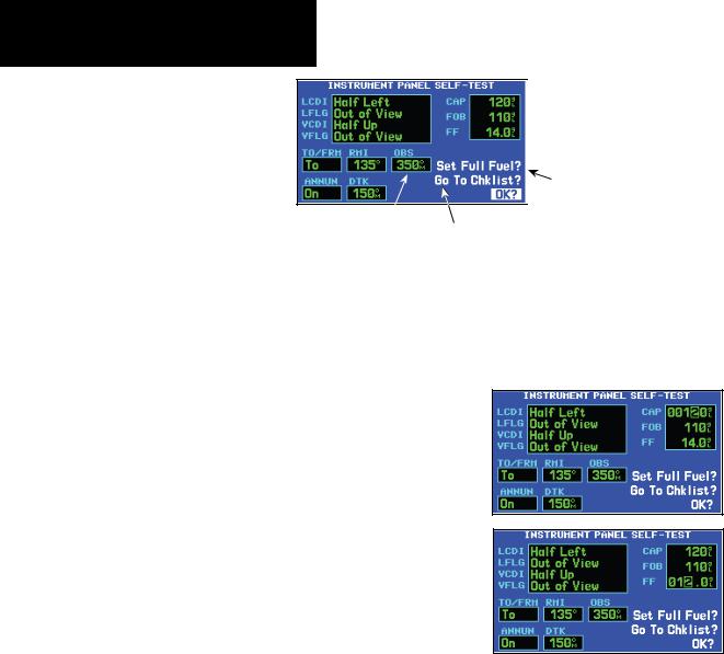
Instrument Panel Self-Test
Once the database has been acknowledged, the instrument panel self-test page will appear. To ensure that your 400W-series unit and any connected instruments are working properly, check for the following indications on your CDI/HSI, RMI, external annuncia- tors and other connected instruments:
•Course deviation
•Glideslope
•TO/FROM flag
•Time to destination
•Bearing to destination
•Desired track
•Distance to dest.
•Ground speed
•All external annunciators (if installed)
The instrument panel self-test page indicates the currently selected OBS course, fuel capacity (CAP), fuel on board (FOB) and fuel flow (FF). The fuel capacity, fuel on board and fuel flow may be manually entered if your installation does not include connection to sensors which automatically provide these figures.
|
} |
Fuel Figures: May be |
|
entered manually if no |
|
|
sensor present |
|
|
|
Select to Set Fuel Level |
|
|
to Full Capacity |
|
|
|
Select to display |
|
|
Checklists Page |
|
|
To enter fuel capacity, fuel on board or fuel flow figures (if not provided by sensors):
1.Turn the large right knob to select the “CAP”, “FOB” or “FF” field.
2.Turn the small and large right knobs to enter the desired figure, then press ENT.
Enter the fuel capacity, fuel on board or fuel flow figures directly onto the appropriate field of the instrument panel self-test page. These figures will automatically be provided if your installation includes connection to external sensors.
6 |
190-00356-00 Rev E |

Fuel On Board and Checklists
The instrument panel self-test page includes selections to set fuel on board (FOB) to full capacity and access the checklists page. This allows you to quickly set fuel to full limits and display any checklists you’ve entered, such as start up or takeoff checklists.
To set fuel on board to full (if not provided by sensor):
1.Turn the large right knob to highlight “Set Full Fuel?”.
Select “Set Full Fuel?” to set fuel on board (FOB) to full capacity.
2.Press ENT and verify that fuel on board (“FOB”) now matches the fuel capacity (CAP) figure. Fuel on board will now be reduced, over time, based on the fuel flow (FF) figure.
TAKEOFF TOUR
Fuel On Board & Checklists
To view the checklists page:
1.Turn the large right knob to highlight “Go To Chklist?” and press ENT.
Select “Go To Chklist?” to display the checklist page and any available checklists. The 400W-series unit can hold up to nine checklists with up to 30 entries in each checklist.
2.Turn the large right knob to select the desired checklist, then follow the steps in Section 9 - Aux Pages - Utility Page to execute each step in the selected checklist.
3.Once you complete the desired checklist(s), press the small right knob to return to the checklists page. Press the small right knob again to return to normal operation on the satellite status or map pages.
Once you’ve verified instrument operation with the instrument panel self-test page displayed, press the ENT key.
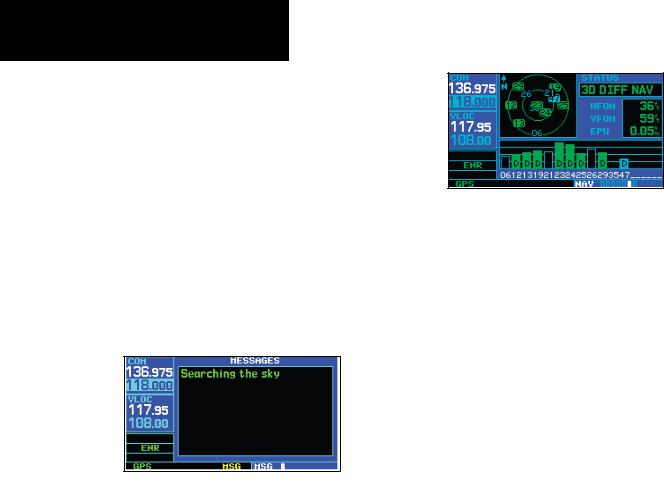
The satellite status page will appear as the 400Wseries unit begins to collect satellite information. An “Acquiring” status will be displayed on the satellite status page, and the signal strength of any satellites received will appear as “bar graph” readings. This is a good indication that you are receiving signals and a position fix will be determined. Following the firsttime use of your 400W-series unit, the time required for a position fix will vary—within two minutes.
190-00356-00 Rev E |
7 |
TAKEOFF TOUR
Acquiring Satellites / Messages
Acquiring Satellites/Messages
If the 400W-series unit has not been operated for a period of six months or more, it may have to “Search the Sky” to collect new data. This means the unit is acquiring satellite data to establish almanac and satellite orbit information, which can take 5 to 10 minutes. The Satellite Status Page displays a “Searching Sky” status, and the message annunciator (MSG) above the MSG key also flashes to alert you of a system message, “Searching the Sky”.
The Time and other data may not be displayed until the unit has acquired enough satellites for a fix.
To view a system message, press the MSG key.
Message Page
The message page will appear and display the status or warning information applicable to the receiver’s current operating condition.
To return to the previous page after viewing a message, press the MSG key again.
The satellite status page shows the ID numbers for the satellites and the relative signal strength of each satellite received (as a “bar graph” reading.
“Searching Sky” indicates that satellite almanac data is not available. The data is recollected from the first available satellite.
“Acquiring” indicates that satellites have been located and information is being acquired, but the receiver does not have enough satellites for a 3-dimen- sional position.
“3D NAV” indicates that a 3-dimensional position is available.
“3D DIFF NAV” indicates when a 3-dimensional position is available and differential corrections are being used.
The “INTEG” annunciator (bottom left corner of the screen) indicates that satellite coverage is insufficient to pass built-in integrity monitoring tests.
8 |
190-00356-00 Rev E |
420W / 430W Only
TAKEOFF TOUR
Selecting COM and VLOC Frequencies
Selecting COM and VLOC Frequencies
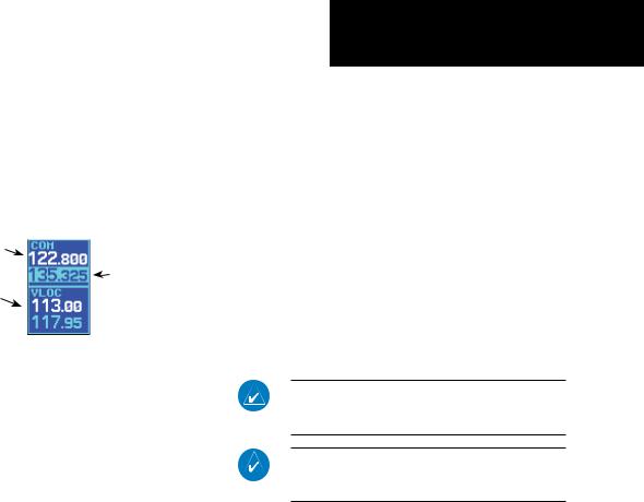
While the 400W-series unit is acquiring a position, let’s take a minute to dial in the active and standby frequencies you’ll be using for the first phase of your flight. The 400W-series display is divided into separate “windows” (or screen areas), including a COM window,
VLOC window, and the GPS window.
COM Window: |
|
|
|
|
|
Active Frequency |
|
COM Window: |
|
|
|
VLOC Window: |
|
Standby Frequency |
|
with tuning cursor |
|
Active Frequency |
|
|
|
|
|
|
|
|
Pushing the small left knob activates the tuning cursor in the desired frequency window. To select the active frequency, you must first enter the frequency in the standby field, and use the COM flip-flop (or VLOC flip-flop) key to move it to the active field.
To change the standby communication (COM) or VLOC frequency:
1.If the tuning cursor is not currently in the desired window (COM or VLOC), press the small left knob momentarily to switch the highlight between the COM and VLOC windows.Adjusting the frequencies with the large and small left knobs will affect the standby frequency.
2.Turn the large left knob to select the desired megahertz (MHz) value. For example, the “135” portion of the frequency “135.325”.
3.Turn the small left knob to select the desired kilohertz (kHz) value. For example, the “.325” portion of the frequency “135.325”.
4.To activate the selected frequency, press the appropriate flip-flop key—COM for communication frequencies or VLOC for VOR/Localizer frequencies.
Once you’ve entered the active frequency, simply repeat steps 1 through 3, above, to enter the standby frequency. After both communication frequencies have been entered, you may elect to keep the COM window ‘hot’ by leaving the cursor on the standby frequency, or move the cursor to the VLOC window by pressing the small left knob.
Once you’ve entered the active frequency, simply repeat steps 1 to 3, above, to enter the standby frequency. After both communication frequencies have been entered, you may elect to keep the COM window “hot” by leaving the cursor on the standby frequency, or move the cursor to the VLOC window by pressing the small left knob.
NOTE: When selecting VLOC frequencies, the tuning cursor automatically returns to the COM window after 30 seconds of inactivity.
NOTE: GPS level of service annunciations (LPV, ENR, etc.) are not applicable to the external CDI (or HSI) when VLOC is active.
These features are only available in the 420W/430W units.
190-00356-00 Rev E |
9 |

TAKEOFF TOUR
Page Groups
Page Groups |
|
|
|
|
|
|
|
|
|
|
|||
|
|
|
|
|
|
D |
|
|
|
|
|||
|
|
|
|
(Large right knob to change page groups) |
|
||||||||
|
|
|
|
|
|
|
|
|
|
|
|
|
|
|
|
NAV Group |
|
|
|
|
|
WPT Group |
|
||||
|
|
|
|
|
|
|
|
||||||
|
|
|
|
|
|
|
|
|
|
|
|
|
|
|
|
|
|
|
|
|
|
|
|
|
|
|
|
|
|
|
|
|
|
|
|
|
|
|
|
|
|
A (Small right knob to select pages within the group)
Default NAV
Map
Terrain
NAVCOM
Position
Satellite Status
VNAV
Arpt Location
Arpt Runway
Arpt Frequency
Arpt Approach
Arpt Arrival
Arpt Departure
Intersection
NDB
VOR
User Waypoint
Selection of any main page is performed using the large and small right knobs. The large right knob selects the page group: NAV, WPT, AUX or
NRST. The small right knob selects the desired page within a group. To quickly select the default NAV page, press and hold the CLR key.
10 |
190-00356-00 Rev E |
A (Large right knob to select pages with the group)
TAKEOFF TOUR
Page Groups
D |
|
(Large right knob to change page groups) |
|
AUX Group |
NRST Group |
|
|
|
|
|
Flight Planning |
|
Nrst Airport |
|
Nrst User Waypnt |
|
|
|
|
|
|
|
|
|
|
Utility |
|
Nrst Intersection |
|
Nrst Center |
|
|
|
|
|
|
|
|
|
|
Setup 1 |
|
Nrst NDB |
|
Nrst Flight Service |
|
|
|
|
|
|
|
|
|
|
Setup 2 |
|
|
|
Nearest VOR |
Nrst Airspace |
|
|
|
|
|
|
FPL Group
Flight plan pages are selected by pressing the FPL key and using the small right knob to select the desired page.
PROC Group
The Procedures pages are selected by pressing the
PROC key and using the small or large right knobs to select a procedure.
|
|
|
|
|
|
|
|
|
|
|
|
|
|
|
|
|
|
|
|
|
|
|
|
Active Flight Plan |
|
Flight Plan Catalog |
|
|
|
|
|
|
|
|
|
|
|
|
|
|
Procedure |
||
|
|
|
|
|
|
|
|
|
|
|
|
|
|
|
|
|
|
|
|
|
|
190-00356-00 Rev E |
11 |
TAKEOFF TOUR
Nav Pages
Nav Pages
The map page is one of seven, or more, pages avail- able under the NAV group*:
• Default NAV page |
• Map page |
• Terrain page |
• NAVCOM page |
• Position page |
• Satellite status page |
• Vertical navigation page
To select the desired NAV page, turn the small right knob until the desired page is displayed.
If you are currently viewing a page that is not part of the NAV group, you can quickly return to the NAV group using the CLR key.
To select the NAV group and display the default NAV page, press and hold CLR.
NAV
7+ available pages* (see list above)
AUX
4 available pages (see Section 9)
WPT
10 available pages (see Section 6)
NRST
8 available pages (see Section 7)
MAIN PAGE GROUPS
In addition to the NAV group of pages, additional groups of pages are available for waypoint information
(WPT), auxiliary (AUX) functions such as flight plan- ning or unit settings, and listings for nearest (NRST) airports or other facilities.
To select the desired page group, turn the large right knob until a page from the desired group is displayed.
To select the desired page within the group, turn the small right knob until the desired page is displayed.
The bottom right corner of the screen indicates the page group currently being displayed (e.g., NAV or NRST), the number of screens available within that group (indicated by square icons) and the placement of the current screen within that group (indicated by a highlighted square icon). To select a different page within the group, turn the small right knob.
* Seven, or more, NAV Pages are available when the 400W-series installation includes connection to traffic, XM radio, and/or weather information sources. See the 400W/500W Series Display Interfaces Pilot’s Guide Addendum, part number 190-00356-31 and the 400W/500W Series Garmin Optional Displays Pilot’s Guide Addendum, part number 190-00356-30.
12 |
190-00356-00 Rev E |
Default Nav Page
During most flights, the default NAV, map and
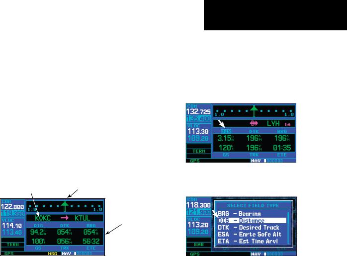
NAVCOM pages will be the primary pages used for navigation. The default NAV page displays a graphic course deviation indicator (CDI), the active leg of your flight plan (as defined by the current “from” and “to” waypoints), and six user-selectable data fields. The default settings for these fields are distance to waypoint (DIS), desired track (DTK), bearing to waypoint (BRG), ground speed (GS), ground track (TRK) and estimated time en route (ETE). See Section 11 for definitions of these navigation terms. The default NAV page is selected by pressing and holding the CLR key or turning the small right knob.
Active Leg of |
Course Deviation Indicator (CDI) |
Flight Plan |
Userselectable Data Fields
Default NAV Page
TAKEOFF TOUR
Default Nav Page
To change the data fields in the corners of the Default NAV Page:
1.Press MENU (with the Map Page displayed).
2.Turn the large right knob to highlight “Change Fields?” and press ENT.
3.Turn the large right knob to highlight the data field you wish to change.
4.Turn the small right knob to select the type of data you want to appear on this field and press ENT.
5.Press the small right knob to remove the cursor.
190-00356-00 Rev E |
13 |
TAKEOFF TOUR
Map Page
Map Page
The map page displays your present position (using an airplane symbol) relative to nearby airports, VORs, NDBs, intersections, user waypoints and airspace boundaries—and your route displayed as a solid line.
Data fields for destination waypoint (WPT), distance to waypoint (DIS), desired track (DTK) and ground speed (GS) appear on the right hand side of the display. These fields are user-selectable to allow you to configure the unit to your own preferences. Available settings include: altitude, bearing, en route safe altitude, estimated time of arrival, minimum safe altitude, and ground track. See Section 11 for definitions of these navigation terms.
Map Display
Data
Fields
Map |
Present |
Desired Track |
Scale with |
Position |
|
declutter |
Map Page |
|
value |
|
The map page combines a moving map display and navigation data for complete situational awareness. Map setup pages are provided to designate the maximum scale at which each map feature will appear. These settings provide an automatic decluttering of the map (based upon your
preferences) as you adjust the scale.
While viewing the map page, you can quickly declutter and remove many of the background map details by pressing the CLR key (repeatedly) until the desired detail is depicted.
To change the map scale, press the or sides of the RNG key.
14 |
190-00356-00 Rev E |

NavCom Page
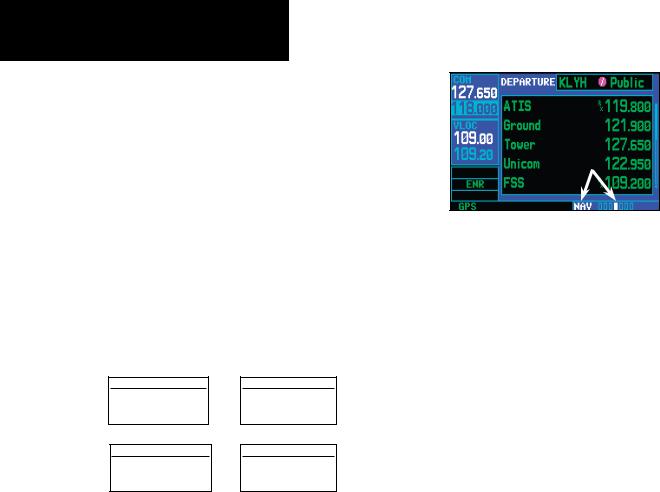
From the default NAV page, simply turn the small right knob to display the map page and again to display the NAVCOM page. The NAVCOM page displays the available frequencies (communications and navigation) for the departure airport, any en route airports that are included in your flight plan, and the final destination airport. When using the direct-to function, frequencies will be listed for the airport nearest to your starting position and the destination airport.
A frequency listed on the NAVCOM page can be quickly transferred to the standby field of the COM or VLOC windows. This time-saving process prevents having to “re-key” a frequency already displayed elsewhere on the screen.
To display the frequency list for the active flight plan or direct-to airport:
1.In the Nav function, turn the small right knob to reach the NAVCOM page.
2.Push the small right knob to activate the cursor on the airport identifier field (in the GPS window). Turn the small right knob to display the list of airports (departure, arrival and en route) for your flight plan or direct-to. Continue to turn the small right knob until the desired airport is selected.
3.Press ENT to display the frequency list for the selected airport.
Press ENT to show the frequencies for the selected airport.
TAKEOFF TOUR
NAVCOM Page
To select a communication or navigation frequency:
1.On the NAVCOM page, push the small right knob to activate the cursor in the GPS window.
2.Turn the large right knob to select the desired frequency from the list.
Selecting a frequency on the NAVCOM page.
3.Press ENT to transfer the selected frequency to the standby field in the COM or VLOC window. COM frequencies will automatically go to the standby field of the COM window and navigation frequencies will automatically go to the standby field of the VLOC window, regardless of which window is currently highlighted by the cursor.
4.To activate the selected frequency, press the
COM flip-flop (or VLOC flip-flop) key.
Swap the standby COM frequency into the active Com frequency location.
190-00356-00 Rev E |
15 |
TAKEOFF TOUR
Direct-To Navigation
Direct-To Navigation
The 400W-series unit can use direct point-to-point navigation to guide you from takeoff to touchdown, even in the IFR environment. Once a destination
is selected, the unit will provide speed, course and distance data based upon a direct course from your present position to your destination. A destination can be selected from any page with the direct-to key.
Destination
Waypoint Identifier
Field
“Activate?” Function Field
Select Direct-To Waypoint Page
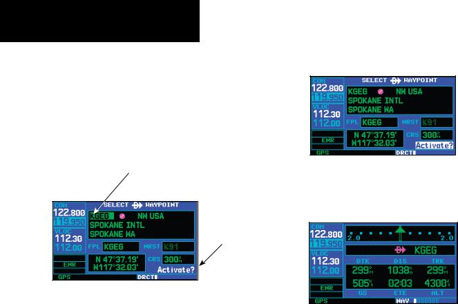
To select a direct-to destination:
1.Press the direct-to key. The Select Direct-To Waypoint page will appear with the destination field highlighted. The direct-to waypoint may also be selected by facility or city name. See Section 3 for more information.
2.Turn the small right knob to enter the first letter of the destination waypoint identifier.The destination waypoint may be an airport, VOR, NDB, intersection or user waypoint, as long as it is in the database or stored in memory as a user waypoint.
3.Turn the large right knob to the right to move the cursor to the next character position.
4.Repeat steps 2 and 3 to spell out the rest of the waypoint identifier.
5.Press ENT to confirm the identifier. The “Activate?” function field will be highlighted.
Confirm the selected direct-to destination by highlighting “Activate?” and pressing ENT.
6.Press ENT to activate a direct-to course to the selected destination.
Once a direct-to destination is selected, press and hold CLR to display the default NAV page.
You can then press and hold the CLR key to return to the default NAV page, as desired.
16 |
190-00356-00 Rev E |
IFR Procedures
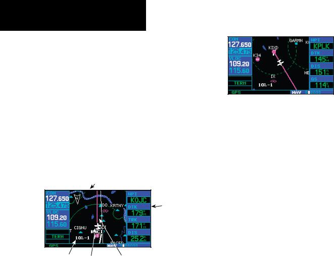
Once the direct-to or flight plan is confirmed, the whole range of instrument procedures is available to you. Departures (SIDs), arrivals (STARs), non-preci- sion and precision approaches are stored within the
NavData card and available using the PROC (procedures) key.
To display the procedures page, press PROC.
The steps required to select and activate an approach, departure or arrival are identical. In this introductory section, we’ll show examples of the steps required to select an approach, but keep in mind the same process also applies to departures and arrivals.
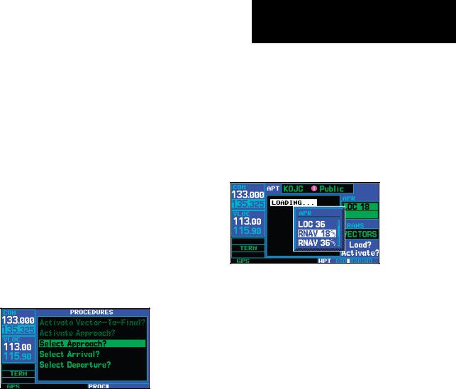
To select an approach, departure, or arrival:
1.Turn the small right knob to select the desired option (“Select Approach?”, “Select Arrival?” or “Select Departure?”) from the procedures page.
Press the PROC key to display the procedures page. Turn the large right knob to select the desired option.
2.Press ENT to display a list of available procedures for the arrival (when using approaches or STARs) or departure (when using SIDs) airport.
3.Turn the small right knob to select the desired procedure and press ENT.
TAKEOFF TOUR
IFR Procedures
4.For approaches, a window appears to select the desired initial approach fix (IAF) or provide a “vectors” option to select just the final course segment of the approach.Turn the small right knob to select the desired option and press ENT. Vectors guidance is relative to the final inbound course. A line is drawn beyond the final approach fix, allowing you to intercept the final course segment beyond its normal limits.
A window will appear to select the desired procedure. Use the large right knob to make your selection.
5.For departures and arrivals, a window appears to select the desired transition. Turn the small right knob to select the desired option and press ENT.
6.With “Load?” highlighted, press ENT to add the procedure to the flight plan or direct-to.
In your flight plan or direct-to, the departure or arrival airport is replaced with the sequence of waypoints contained within the selected procedure.
190-00356-00 Rev E |
17 |

TAKEOFF TOUR
Nearest Pages
Nearest (NRST) Pages
The NRST main page groups provides listings for nearest airports or other facilities. The NRST group provides detailed information on the 25 nearest airports, VORs, NDBs, intersections and user-created waypoints within 200 NM of your current position. In addition, pages are also provided to display the five nearest center (ARTCC/FIR) and Flight Service Station (FSS) points of communication, plus alert you to any special-use or controlled airspace you may be in or near.
The nearest airport page is one of eight pages available under the NRST group:
•Nearest airport page
•Nearest intersection page
•Nearest NDB page
•Nearest VOR page
•Nearest user waypoints page
•Nearest ARTCC page
•Nearest FSS page
•Nearest airspace page
To display the NRST pages:
1.If necessary, press the small right knob to remove the cursor from the page.
2.Turn the large right knob to select the NRST page group, as indicated by “NRST” appearing in the lower right corner of the screen.
To display a list of nearby airports, turn the large right knob to select the NRST page group and (if needed) the small right knob to select the nearest airport page.
3.Press and then turn the large right knob to select the desired NRST page.
To scroll through the list, press the small right knob, then turn the large right knob.
18 |
190-00356-00 Rev E |

Nearest Airport
You may examine both the communication frequencies and runway information directly from the nearest airport page. As discussed earlier for the NAVCOM page, you may also place any displayed frequency into the standby COM or VLOC field by highlighting the frequency with the cursor and pressing ENT.
To view additional information for a nearby airport from the Nearest Airport page:
1.Press the small right knob to activate the cursor.
2.Turn the large right knob to select the desired airport from the list.
3.Press ENT to display waypoint (WPT) information pages for the selected airport.
Additional information for a nearby airport is available by highlighting an identifier on the list and pressing ENT.
4.To display runway and frequency information, press the small right knob to remove the cursor and turn the small right knob to display the desired information page.
TAKEOFF TOUR
Nearest Airport
The nearest airport page may be used in conjunction with the direct-to key to quickly set a course to a nearby facility in an in-flight emergency. Selecting a nearby airport as a direct-to destination will override your flight plan or cancel a previously selected directto destination. You’ll still have the option of returning to your flight plan by cancelling the direct-to.
To select a nearby airport as a direct-to destination:
From the nearest airport page...
1.Press the small right knob to activate the cursor.
2.Turn the large right knob to select the desired airport from the list.
3.Press direct-to, ENT, and ENT (again) to navigate to the nearby airport.
To select a nearby airport as a new destination, highlight its identifier, press direct-to, ENT, and ENT (again).
From an airport information page...
1.Press direct-to, ENT, and ENT (again) to navigate to the nearby airport.
190-00356-00 Rev E |
19 |

TAKEOFF TOUR
Nearest Airspace
Nearest Airspace Page
The last page in the NRST group, the nearest airspace page, provides information for up to nine controlled or special-use airspaces near or in your flight path. Airspace information appears on this page based upon the same criteria used for airspace alert messages. Nearby airspace information and airspace alert messages are provided according to the following conditions:
•If your projected course will take you inside an airspace within the next ten minutes, the message “Airspace ahead -- less than 10 minutes” will appear.
•If you are within two nautical miles of an airspace and your current course will take you inside, the message “Airspace near and ahead” will appear.
•If you are within two nautical miles of an airspace and your current course will not take you inside, the message “Near airspace less than 2NM” will appear.
•If you have entered an airspace, the message
“Inside Airspace” will appear.
By default, airspace alert messages are turned off. When turned on, the message (MSG) annunciator located directly above the MSG key will flash to alert you to the airspace message. (See Section 9 Aux Pages - Setup 1 for information on enabling airspace alert messages.)
To view an airspace alert message:
1.Press the MSG key.The message page appears with the alert message.
When an airspace alert occurs, the message (MSG) annunciator will flash. Press MSG to view the alert message.
2.Press MSG again to return to the previous display.
To view nearest airspace information:
1.Turn the large right knob to reach the NRST function.
To view additional information about the airspace, select the nearest airspace page. Detailed information is available by highlighting the airspace name and pressing ENT.
2. Turn the small right knob to reach the Nearest Airspace page.
Note that the airspace alerts are based upon threedimensional data (latitude, longitude and altitude) to avoid nuisance alerts. The alert boundaries for controlled airspace are also sectorized to provide complete information on any nearby airspace. Additional information about a nearby airspace—such as controlling agency, frequency and floor/ceiling limits—is available
20 |
190-00356-00 Rev E |
Loading...