


G500
Cockpit
Reference Guide
© 2009 Garmin Ltd. or its subsidiaries. All rights reserved.
This manual reflects the operation of System Software version 3.00, or later. Some differences in operation may be observed when comparing the information in this manual to later software versions.
Garmin International, Inc., 1200 East 151st Street, Olathe, Kansas 66062, U.S.A.
Tel: 913/397.8200 |
Fax: 913/397.8282 |
Garmin AT, Inc., 2345 Turner Road SE, Salem, OR 97302, U.S.A. |
|
Tel: 503/391.3411 |
Fax 503/364.2138 |
Garmin (Europe) Ltd., Liberty House, Bulls Copse Road, Hounsdown Business Park, Southampton, SO40 |
|
9RB, U.K. |
|
Tel. +44 (0) 870 850 1243 |
Fax +44 (0) 238 052 4004 |
Garmin Corporation, No. 68, Jangshu 2nd Road, Shijr, Taipei County, Taiwan |
|
Tel: 886/02.2642.9199 |
Fax: 886/02.2642.9099 |
www.garmin.com
At Garmin, we value your opinion. For comments about this guide, please e-mail: Techpubs.Salem@garmin.com.
Except as expressly provided herein, no part of this manual may be reproduced, copied, transmitted, disseminated, downloaded or stored in any storage medium, for any purpose without the express written permission of Garmin. Garmin hereby grants permission to download a single copy of this manual and of any revision to this manual onto a hard drive or other electronic storage medium to be viewed for personal use, provided that such electronic or printed copy of this manual or revision must contain the complete text of this copyright notice and provided further that any unauthorized commercial distribution of this manual or any revision hereto is strictly prohibited.
Garmin®, Garmin SVT™, and GDU™ 620®,are registered trademarks of Garmin Ltd. or its subsidiaries. FliteCharts®, and SafeTaxi® are registered trademarks of Garmin Ltd. or its subsidiaries. These trademarks may not be used without the express permission of Garmin.
NavData® is a registered trademark of Jeppesen, Inc.; SkyWatch® is a registered trademark of L-3 Communications; and XM® is a registered trademark of XM Satellite Radio, Inc.
June 2009 |
Printed in the U.S.A. |

LIMITED WARRANTY
This Garmin product is warranted to be free from defects in materials or workmanship for two years from the date of purchase. Within this period, Garmin will, at its sole option, repair or replace any components that fail in normal use. Such repairs or replacement will be made at no charge to the customer for parts and labor, provided that the customer shall be responsible for any transportation cost. This warranty does not cover failures due to abuse, misuse, accident, or unauthorized alterations or repairs.
THE WARRANTIES AND REMEDIES CONTAINED HEREIN ARE EXCLUSIVE AND IN LIEU OF ALL OTHER WARRANTIES EXPRESS OR IMPLIED OR STATUTORY, INCLUDING ANY LIABILITY ARISING UNDER ANY WARRANTY OF MERCHANTABILITY OR FITNESS FOR A PARTICULAR PURPOSE, STATUTORY OR OTHERWISE. THIS WARRANTY GIVES YOU SPECIFIC LEGAL RIGHTS, WHICH MAY VARY FROM STATE TO STATE.
IN NO EVENT SHALL GARMIN BE LIABLE FOR ANY INCIDENTAL, SPECIAL, INDIRECT OR CONSEQUENTIAL DAMAGES, WHETHER RESULTING FROM THE USE, MISUSE, OR INABILITY TO USE THIS PRODUCT OR FROM DEFECTS IN THE PRODUCT. Some states do not allow the exclusion of incidental or consequential damages, so the above limitations may not apply to you.
Garmin retains the exclusive right to repair or replace the unit or software, or to offer a full refund of the purchase price, at its sole discretion. SUCH REMEDY SHALL BE YOUR SOLE AND EXCLUSIVE REMEDY FOR ANY BREACH OF WARRANTY.
To obtain warranty service, contact your local Garmin Authorized Service Center. For assistance in locating a Service Center near you, visit the Garmin web site at http://www.garmin.com or contact Garmin Customer Service at 800.800.1020.
190-01102-03 Rev B |
G500 Cockpit Reference Guide |
i |

WARNINGS, CAUTIONS, AND NOTES
WARNINGS, CAUTIONS, AND NOTES
Warnings, Cautions, & Notes
WARNING: Navigation and terrain separation must NOT be predicated upon the use of the terrain function.The GDU 620 Terrain Proximity feature is NOT intended to be used as a primary reference for terrain avoidance and does not relieve the pilot from the responsibility of being aware of surroundings during flight. The Terrain Proximity feature is only to be used as an aid for terrain avoidance and is not certified for use in applications requiring a certified terrain awareness warning system. Terrain data is obtained from third party sources. Garmin is not able to independently verify the accuracy of the terrain data.
WARNING: The displayed minimum safe altitudes (MSAs) are only advisory in nature and should not be relied upon as the sole source of obstacle and terrain avoidance information. Always refer to current aeronautical charts for appropriate minimum clearance altitudes.
WARNING: The Garmin GDU 620 has a very high degree of functional integrity. However, the pilot must recognize that providing monitoring and/ or self-test capability for all conceivable system failures is not practical. Although unlikely, it may be possible for erroneous operation to occur without a fault indication shown by the GDU 620. It is thus the responsibility of the pilot to detect such an occurrence by means of cross-checking with all redundant or correlated information available in the cockpit.
WARNING: The altitude calculated by GPS receivers is geometric height above Mean Sea Level and could vary significantly from the altitude displayed by pressure altimeters, such as the output from the GDC 74A Air Data Computer, or other pressure altimeters in aircraft. GPS altitude should never be used for vertical navigation. Always use pressure altitude displayed by the GDU 620 PFD or other pressure altimeters in aircraft.
WARNING: Do not use outdated database information. Databases used in the G500 system must be updated regularly in order to ensure that the information remains current. Pilots using an outdated database do so entirely at their own risk.
ii |
G500 Cockpit Reference Guide |
190-01102-03 Rev B |

WARNINGS, CAUTIONS, AND NOTES
WARNING: Do not use basemap (land and water data) information for primary navigation. Basemap data is intended only to supplement other approved navigation data sources and should be considered as an aid to enhance situational awareness.
WARNING: Traffic information shown on the GDU 620 Multi-Function Display is provided as an aid in visually acquiring traffic. Pilots must maneuver the aircraft based only upon ATC guidance or positive visual acquisition of conflicting traffic.
WARNING: XM Weather should not be used for hazardous weather penetration.Weather information provided by the GDL 69/69A is approved only for weather avoidance, not penetration.
WARNING: NEXRAD weather data is to be used for long-range planning purposes only. Due to inherent delays in data transmission and the relative age of the data, NEXRAD weather data should not be used for short-range weather avoidance.
WARNING: For safety reasons, GDU 620 operational procedures must be learned on the ground.
WARNING: To reduce the risk of unsafe operation, carefully review and understand all aspects of the G500 Pilot’s Guide. Thoroughly practice basic operation prior to actual use. During flight operations, carefully compare indications from the GDU 620 to all available navigation sources, including the information from other NAVAIDs, visual sightings, charts, etc. For safety purposes, always resolve any discrepancies before continuing navigation.
WARNING: Never use the G500 to attempt to penetrate a thunderstorm. Both the FAA Advisory Circular, Subject: Thunderstorms, and the Airman’s Information Manual (AIM) recommend avoiding “by at least 20 miles any thunderstorm identified as severe or giving an intense radar echo”.
WARNING: Exceeding 200 deg/second in pitch or roll may invalidate AHRS attitude provided to the GDU 620. Exceeding 450 KIAS may invalidate ADC information provided to the GDU 620.
NOTES AND CAUTIONS, WARNINGS,
190-01102-03 Rev B |
G500 Cockpit Reference Guide |
iii |

WARNINGS, CAUTIONS, AND NOTES
WARNINGS, CAUTIONS, AND NOTES
WARNING: Because of anomalies in the earth’s magnetic field, operating the G500 within the following areas could result in loss of reliable attitude and heading indications. North of 70° North latitude and south of 70° South latitude.An area north of 65° North latitude and between longitude 75° West and 120° West. An area south of 55° South latitude between longitude 120° East and 165° East.
WARNING: Do not use Terrain-SVT information for primary terrain avoidance. Terrain-SVT is intended only to enhance situational awareness.
CAUTION: The United States government operates the Global Positioning System and is solely responsible for its accuracy and maintenance. The GPS system is subject to changes which could affect the accuracy and performance of all GPS equipment. Portions of the Garmin GDU 620 utilize GPS as a precision electronic NAVigation AID (NAVAID). Therefore, as with all NAVAIDs, information presented by the GDU 620 can be misused or misinterpreted and therefore, become unsafe.
CAUTION: The Garmin GDU 620 does not contain any user-serviceable parts. Repairs should only be made by an authorized Garmin service center. Unauthorized repairs or modifications could void both the warranty and pilot’s authority to operate this device under FAA/FCC regulations.
CAUTION: The GDU 620 PFD and MFD displays use a lens coated with a special anti-reflective coating that is very sensitive to skin oils, waxes, and abrasive cleaners. CLEANERS CONTAINING AMMONIA WILL HARM THE ANTI-REFLECTIVE COATING. It is very important to clean the lens using a clean, lint-free cloth and an eyeglass lens cleaner that is specified as safe for anti-reflective coatings.
NOTE: Interference from GPS repeaters operating inside nearby hangars can cause an intermittent loss of attitude and heading displays while the aircraft is on the ground. Moving the aircraft more than 100 feet away from the source of the interference should alleviate the condition.
iv |
G500 Cockpit Reference Guide |
190-01102-03 Rev B |

WARNINGS, CAUTIONS, AND NOTES
NOTE: All visual depictions contained within this document, including screen images of the GDU 620 bezel displays, are subject to change and may not reflect the most current G500 system. Depictions of equipment may differ slightly from the actual equipment.
NOTE: This product, its packaging, and its components contain chemicals known to the State of California to cause cancer, birth defects, or reproductive harm. This notice is being provided in accordance with California’s Proposition 65. If you have any questions or would like additional information, please refer to our web site at www.garmin.com/ prop65.
NOTE: This device complies with part 15 of the FCC Rules. Operation is subject to the following two conditions: (1) this device may not cause harmful interference, and (2) this device must accept any interference received, including interference that may cause undesired operation.
NOTE: Terrain data is not displayed when the aircraft latitude is greater than 75° North or 60° South.
NOTE: Terrain-SVT is standard when the Synthetic Vision Technology™ (SVT) option is installed. The TAWS option will take precedence over Terrain-SVT.
NOTES AND CAUTIONS, WARNINGS,
190-01102-03 Rev B |
G500 Cockpit Reference Guide |
v |

Record of Revisions
Part Number |
Revision |
Date |
Page |
Description |
|
Range |
|||||
|
|
|
|
||
|
|
|
|
|
|
190-01102-03 |
A |
5/28/09 |
All |
Production Release |
|
190-1102-03 |
B |
6/18/09 |
Cover |
Updated logo to meet |
|
|
|
|
|
guidelines and added Garmin |
|
|
|
|
|
to SVT™. |
|
|
|
|
|
|
vi |
G500 Cockpit Reference Guide |
190-01102-03 Rev B |

TABLE OF CONTENTS
Contents |
|
Warnings, Cautions, & Notes ............................................................................ |
ii |
Introduction...................................................................................................... |
1 |
Primary Flight Display (PFD)............................................................................. |
2 |
Airspeed Tape.............................................................................................................................. |
4 |
Altitude Tape............................................................................................................................... |
5 |
Barometric Pressure..................................................................................................................... |
5 |
Barometric Minimums Bug........................................................................................................... |
6 |
Altitude Bug................................................................................................................................ |
7 |
Wind Vectors............................................................................................................................... |
8 |
Vertical Speed (V/S) ..................................................................................................................... |
8 |
Vertical Deviation Indicator (VDI) ................................................................................................. |
9 |
Outside Air Temperature (OAT)..................................................................................................... |
9 |
Attitude Indicator ...................................................................................................................... |
10 |
Horizontal Situation Indicator (HSI): Aircraft Heading .................................................................. |
11 |
Adjusting the Course Pointer ..................................................................................................... |
12 |
HSI Bearing Pointers .................................................................................................................. |
12 |
Autopilot (AP)................................................................................................. |
15 |
Heading .................................................................................................................................... |
15 |
Autopilot Test............................................................................................................................ |
15 |
Altitude Capture (Optional Interface) ......................................................................................... |
16 |
Autopilot Navigation ................................................................................................................. |
16 |
Autopilot Operation with the GDU 620 Emulating GPSS............................................................. |
17 |
Additional Features ........................................................................................ |
18 |
Garmin Synthetic Vision Technology™ (Optional)......................................................................... |
18 |
Displaying Garmin SVT™ Terrain................................................................................................. |
19 |
Displaying Heading on the Horizon ............................................................................................ |
19 |
Displaying Airport Signs............................................................................................................. |
19 |
Multi-Function Display (MFD)......................................................................... |
20 |
Page Navigation - Moving Between Pages ................................................................................. |
21 |
Changing Settings within a Page................................................................................................ |
21 |
Default Map Page...................................................................................................................... |
21 |
MFD Soft Key Map..................................................................................................................... |
22 |
Map Group ..................................................................................................... |
23 |
Navigation Map 1 and Navigation Map 2 Pages......................................................................... |
23 |
Decluttering (DCLTR) the Map Pages .......................................................................................... |
24 |
Traffic Map Page (Optional) ....................................................................................................... |
27 |
Terrain Page .............................................................................................................................. |
31 |
Terrain Pop-Up Alerts................................................................................................................. |
33 |
WX Group ....................................................................................................... |
34 |
WX Data Link Map Pages .......................................................................................................... |
34 |
CONTENTS OF TABLE
190-01102-03 Rev B |
G500 Cockpit Reference Guide |
vii |

TABLE OF CONTENTS
TABLE OF CONTENTS
Customizing the Weather Map................................................................................................... |
34 |
Displaying Surface Data and Winds Aloft.................................................................................... |
36 |
Weather Radar (Optional) .............................................................................. |
37 |
Weather Radar Map Page.......................................................................................................... |
37 |
Airborne Color Weather Radar ................................................................................................... |
38 |
Aux Group ...................................................................................................... |
41 |
System Setup Page .................................................................................................................... |
41 |
XM® Information Page (Optional) .............................................................................................. |
46 |
XM® Radio Page (Optional) ....................................................................................................... |
47 |
System Status Page ................................................................................................................... |
49 |
Flight Plan Group ........................................................................................... |
50 |
Active Flight Plan Page .............................................................................................................. |
50 |
Viewing Your Active Flight Plan .................................................................................................. |
50 |
Waypoint Information Page........................................................................................................ |
51 |
Charts Page (Optional) .............................................................................................................. |
52 |
Change Day/Night View............................................................................................................. |
52 |
Viewing Charts and Panning...................................................................................................... |
52 |
Viewing NOTAMs ...................................................................................................................... |
53 |
Selecting a Chart....................................................................................................................... |
53 |
Selecting Other Charts............................................................................................................... |
54 |
Chart Information...................................................................................................................... |
55 |
Alerts .............................................................................................................. |
56 |
On Screen Alerts........................................................................................................................ |
56 |
Terrain-SVT™ Alerts ................................................................................................................... |
58 |
Symbols .......................................................................................................... |
59 |
Map Page Symbols .................................................................................................................... |
59 |
SafeTaxi® Symbols ..................................................................................................................... |
60 |
Traffic Symbols .......................................................................................................................... |
60 |
Terrain Obstacle Symbols ........................................................................................................... |
61 |
Map Toolbar Symbols ................................................................................................................ |
61 |
XM® Weather Toolbar Symbols................................................................................................... |
62 |
Miscellaneous Symbols .............................................................................................................. |
63 |
viii |
G500 Cockpit Reference Guide |
190-01102-03 Rev B |
PRIMARY FLIGHT DISPLAY (PFD)
Introduction
This reference guide covers the operation of the GDU 620 as integrated in the G500 system. The G500 Avionics Display System is an advanced technology avionics suite designed to replace the traditional flight instrument cluster. The system combines primary flight instrumentation, navigational information, and a moving map all displayed on dual 6.5 inch color screens. The G500 system is composed of sub-units or Line Replaceable Units (LRUs). LRUs have a modular design and can be installed directly behind the instrument panel or in a separate avionics bay if desired. This design greatly eases troubleshooting and maintenance of the G500 system. A failure or problem can be isolated to a particular LRU, which can be replaced quickly and easily. Each LRU has a particular function, or set of functions, that contributes to the system’s operation. For more details on the G500 system, refer to the G500 Pilot’s Guide, P/N 190-01102-02 Rev. A or later.
PFD/MFD
DISPLAY FLIGHT PRIMARY
190-01102-03 Rev B |
G500 Cockpit Reference Guide |
1 |
PRIMARY FLIGHT DISPLAY (PFD)
PRIMARY FLIGHT DISPLAY
Primary Flight Display (PFD)
1
 18
18
17
2
3 |
|
4 |
16 |
|
|
5 |
15 |
|
|
6 |
14 |
|
|
7 |
|
8 |
13 |
9 |
10 |
11 |
12 |
Primary Flight Display (PFD)
2 |
G500 Cockpit Reference Guide |
190-01102-03 Rev B |

PRIMARY FLIGHT DISPLAY (PFD)
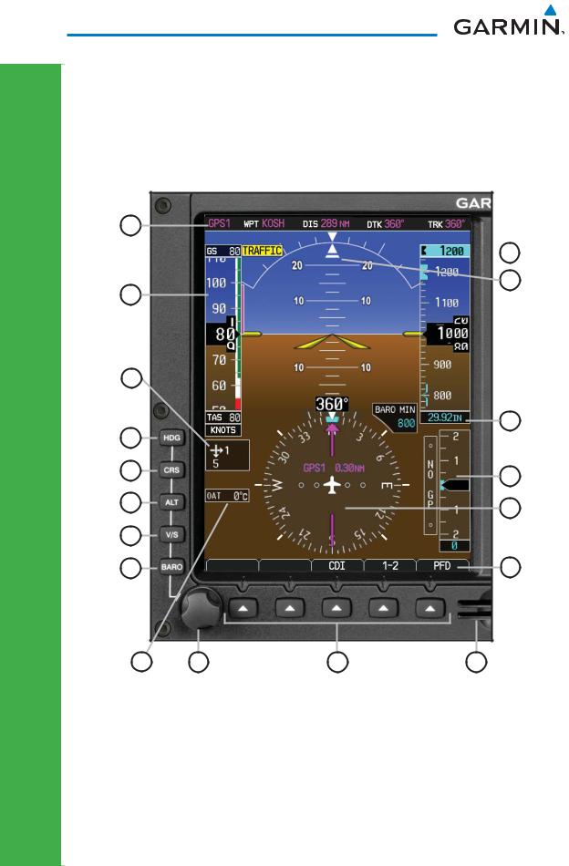
1 |
NAV Status Bar: Displays which GPS is selected as the Active Source, Active Waypoint |
|
(WPT), Distance to Waypoint (DIS), Desired Track (DTK) and Current Track (TRK). |
||
|
||
2 |
Airspeed Tape: Displays Groundspeed (GS), Airspeed Trend, Current Airspeed, |
|
and True Airspeed (TAS). |
||
|
3Wind Vector: Displays direction and speed of wind.
4Heading Select Key: Press HDG and turn PFD knob to set heading bug.
5
Course Select Key: Press CRS and turn PFD knob to set the course of the selected source (VOR1, VOR2, GPS1, or GPS2).
6Altitude Select Key: Press ALT and turn PFD knob to set altimeter bug.
7V/S (Vertical Speed) Select Key: Press V/S and turn PFD knob to set V/S bug.
8
Barometer Select Key: Press BARO and turn PFD knob to change barometric setting.
9 Outside Air Temperature (OAT): Displays the current outside air temperature.
10
PFD Knob: Turn PFD knob to change bug settings, Heading Bug, Course, Altitude Bug, V/S Bug, and Barometer setting.
11 Soft Keys: Used to select available options on PFD or MFD.
12
SD Card Slots, Upper and Lower: The upper slot is used for updating databases or software, the lower slot is for the database card.
Soft Key Labels: Located on the bottom screen of the PFD and MFD. Selection is done by pressing the corresponding soft key. Soft keys that are available
13have the labels shown as white text on a black background. Soft keys that are selected have the labels shown as black text on a gray background. Soft keys that are unavailable have the labels shown as gray text on a black background.
14
Horizontal Situation Indicator (HSI): Displays the Selected Heading Box, Current Heading, Turn Rate Markings, and Heading Trend.
15Vertical Speed Tape: Displays Vertical Speed and the Vertical Speed Bug
16Barometric (BARO) Setting: Displays the current setting of barometric pressure. Roll Pointer and Slip/Skid Indicator: The slip/skid indicator is the bar beneath the
17roll pointer. The indicator moves with the roll pointer and laterally away from the pointer to indicate lateral acceleration (slip/skid).
18
Altitude Tape: Displays Current Altitude, Altitude Trend, Altitude Bug, Altitude Minimums Bug, and BARO setting.
DISPLAY FLIGHT PRIMARY
190-01102-03 Rev B |
G500 Cockpit Reference Guide |
3 |

PRIMARY FLIGHT DISPLAY (PFD)
PRIMARY FLIGHT DISPLAY
Airspeed Tape
The upper left portion of the PFD display provides Groundspeed, Airspeed Trend, Current Airspeed, and True Airspeed information. Current Airspeed is normally shown in white on the black pointer. The Trend Indicator (magenta line) indicates what the airspeed will be in six seconds, if the current rate of acceleration is maintained. If the current acceleration will cause the airspeed to exceed VNE in six seconds, the airspeed is displayed in yellow. If the current airspeed exceeds VNE, the pointer changes to red with white text.
Groundspeed
VNE
VN0
VFE |
|
|
|
Trend Indicator |
|
|
|
Current
VS1 Airspeed
VS0
True Airspeed
Typical Airspeed Tape Markings |
Airspeed Tape |
VLE
VYSE
Overspeed 
VMCA
Overspeed Indication |
Additional Reference Markings |
4 |
G500 Cockpit Reference Guide |
190-01102-03 Rev B |
PRIMARY FLIGHT DISPLAY (PFD)
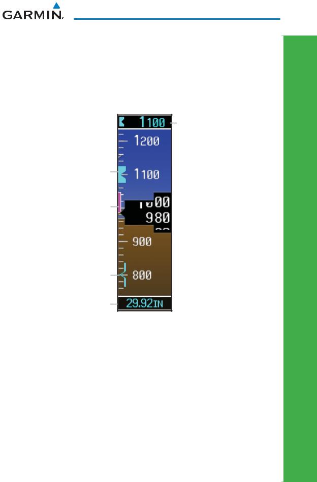
Altitude Tape
The upper right portion of the PFD displays the Altitude Bug setting, Current Altitude, Altitude Trend, Altitude Minimums Bug, and the current BARO Setting. The Altitude Trend indicates what the altitude will be in six seconds if the current vertical speed is maintained.
Altitude Bug Setting
Altitude Bug
Altitude Trend
 Current Altitude
Altitude Minimums Bug
BARO Setting
Altitude Tape
Barometric Pressure
The Barometric Pressure (BARO setting) is displayed at the bottom of the altitude tape. To change the BARO setting, press the BARO key and turn the PFD knob to the desired pressure. To select standard pressure (29.92IN), press the PFD knob.
DISPLAY FLIGHT PRIMARY
190-01102-03 Rev B |
G500 Cockpit Reference Guide |
5 |
PRIMARY FLIGHT DISPLAY (PFD)
PRIMARY FLIGHT DISPLAY
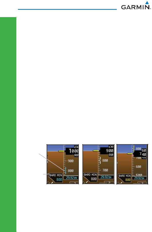
Barometric Minimums Bug
For altitude awareness, a barometric Altitude Minimums Bug commonly referred to as the Minimums Bug, can be set. When active and within 2500 feet of the selected minimums altitude, the minimums bug setting is displayed to the bottom left of the altimeter. When set, a bug appears parked at the bottom of the altitude tape and moves up the tape as the set altitude comes into view.
•When the aircraft altitude descends to within 2500 feet of the selected altitude minimums setting, the BARO MIN box appears with the altitude value in cyan text. Once in range, the Minimums Bug appears in cyan on the altitude tape. A portion of the Minimums Bug will
be displayed at the bottom of the altitude tape if the selected altitude minimums bug is off of the tape.
•When the aircraft is within 100 feet of the selected altitude minimums setting, the bug and the altitude text turn white.
•Once the aircraft reaches the selected altitude minimums setting, the bug and the altitude text turn yellow and the aural alert, “Minimums, minimums” is heard one time.
Bug and text are |
Bug and text are |
Bug and text |
|
are yellow when |
|||
cyan within 2500 ft |
white within 100 ft |
||
altitude Reached |
|||
|
|
Minimums
Bug
Minimums
Box
Minimums Annunciations
Alerting is inhibited while the aircraft is on the ground and also, if a value has been set for altitude alerting, until the aircraft reaches 150 feet above the setting for the alert.
6 |
G500 Cockpit Reference Guide |
190-01102-03 Rev B |

PRIMARY FLIGHT DISPLAY (PFD)
To set the altitude for the Minimums Bug:
1)While viewing the Active Flight Plan page of the FPL Group, press the small MFD knob to activate the cursor.
2)Turn the large MFD knob to the ALTITUDE portion of the MINIMUMS section.
3)Turn the small MFD knob to enter the desired altitude. Press the ENT key to confirm selection.
4)When finished, press the small MFD knob to exit the MINIMUMS box.
NOTE: If you highlight the Altitude Field in the MINIMUMS section on the FPL page and press the CLR key, it will clear the entry and the minimums functionality will be turned off.
Altitude Bug
The Altitude Bug is displayed on the Altitude Tape at the selected altitude bug setting. A portion of the Altitude Bug will be displayed at the top or bottom of the altitude tape if the selected altitude bug is off of the tape.
Altitude Bug
Setting
Altitude Bug
Altitude Bug
The Altitude Bug provides visual and aural altitude alerting. Aural alerting occurs within 200 feet of the Altitude Bug setting or when deviating beyond 200 feet of the bug.
Within 1000 ft Within 200 ft
Deviation of
+/- 200ft
Altitude Bug Indications
DISPLAY FLIGHT PRIMARY
190-01102-03 Rev B |
G500 Cockpit Reference Guide |
7 |

PRIMARY FLIGHT DISPLAY (PFD)
PRIMARY FLIGHT DISPLAY
Wind Vectors
The PFD will display a Wind Vector Field to the left of the HSI when configured by the user. There are four different styles of wind vector displays available. Refer to the System Setup page in the AUX Group section of this guide for instructions on selecting wind vector style. Wind Vectors can only be calculated when the aircraft is in the air.
Wind Vector
Field
Wind Vector Display
Vertical Speed (V/S)
The Vertical Speed Tape and Vertical Speed Bug are displayed below the Altitude Tape.
Current Vertical Speed
Vertical Speed Bug
Vertical Speed Bug Setting
Vertical Speed
8 |
G500 Cockpit Reference Guide |
190-01102-03 Rev B |
PRIMARY FLIGHT DISPLAY (PFD)
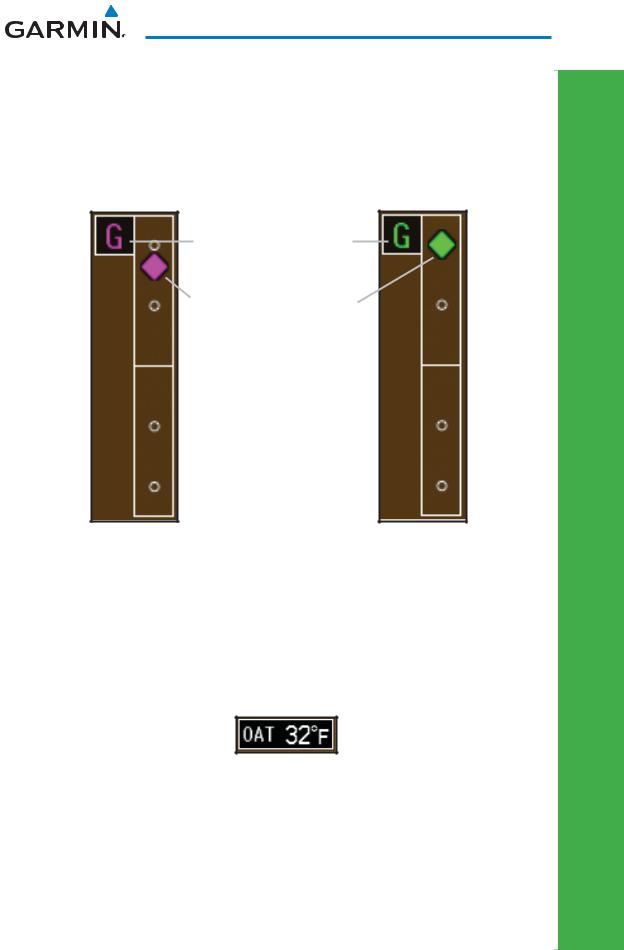
Vertical Deviation Indicator (VDI)
The Vertical Deviation Indicator is displayed for GPS and ILS approaches with vertical guidance. The GPS approach glidepath is shown in magenta (G and indicator), while the ILS approach glideslope is shown in green (G and indicator.)
Vertical Deviation Source
Vertical Deviation Indicator
GPS Approach |
ILS Approach |
Outside Air Temperature (OAT)
The Outside Air Temperature, as sensed from the temperature probe on the aircraft, is displayed to the left of the HSI. This temperature is used in calculating the true airspeed.
DISPLAY FLIGHT PRIMARY
190-01102-03 Rev B |
G500 Cockpit Reference Guide |
9 |

PRIMARY FLIGHT DISPLAY (PFD)
PRIMARY FLIGHT DISPLAY
Attitude Indicator
The standby mechanical Attitude Indicator in your aircraft is either a Ground Pointer or a Roll Pointer configuration. The GDU 620 Attitude Indicator has been configured in either a Ground Pointer or a Roll Pointer configuration to match the configuration of your aircraft’s standby Attitude Indicator.
In an aircraft with an Attitude Indicator that has a Ground Pointer, the pointer above the roll scale shifts with the roll or bank angle of the aircraft to keep the Roll Scale Zero Pointer pointing towards the ground.
 Roll Scale Zero Pointer
Roll Pointer
 Roll Scale
G500 Attitude Indicator with a Ground Pointer Configuration in a Left Turn
In an aircraft with an Attitude Indicator that has a Sky Pointer, the pointer below the roll scale shifts with the roll or bank angle of the aircraft to keep the Roll Pointer pointing towards the sky.
Roll Scale Zero Pointer
Roll Pointer
 Roll Scale
G500 Attitude Indicator with a Sky Pointer Configuration in a Left Turn
10 |
G500 Cockpit Reference Guide |
190-01102-03 Rev B |
PRIMARY FLIGHT DISPLAY (PFD)
The Slip/Skid Indicator is the bar beneath the roll pointer. The indicator moves with the roll pointer and moves laterally away from the pointer to indicate lateral acceleration. Slip/skid is indicated by the location of the bar relative to the pointer. One bar displacement from the roll pointer is equivalent to one ball displacement on a traditional Slip/Skid Indicator.
Roll Scale Zero |
Roll Pointer |
Slip/Skid Indicator |
||
|
|
|
|
|
|
|
|
|
|
|
|
|
|
|
Slip/Skid Indicator
Horizontal Situation Indicator (HSI): Aircraft Heading
The top of the HSI displays current heading, current GPS track (magenta diamond), heading trend, and turn rate markings. The heading trend indicates what the aircraft heading will be in six seconds if the heading rate remains unchanged. The turn rate markings, along with the heading trend, display standard and half-standard rate turns.
Current Heading |
Turn Rate Markings |
|
|
|
|
|
|
|
Current GPS Track |
Heading Trend |
HSI Heading Markings
NOTE: If magnetic heading is lost, GPS ground track will be displayed in place of heading. If magnetic heading and GPS ground track are lost, a red “X” will appear in place of heading.
DISPLAY FLIGHT PRIMARY
190-01102-03 Rev B |
G500 Cockpit Reference Guide |
11 |
PRIMARY FLIGHT DISPLAY (PFD)
PRIMARY FLIGHT DISPLAY
Adjusting the Course Pointer
Press the CRS key and turn the PFD knob to select a course for a VOR or OBS mode course.
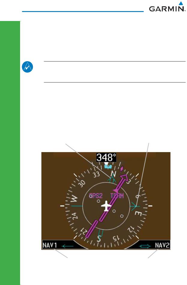
HSI Bearing Pointers
NOTE: The Bearing Pointer for navigation source 1 (BRG1) will be an arrow with a single line. The Bearing Pointer for navigation source 2 (BRG2) will be an arrow with a double line.
To toggle between the available bearing pointers, press the PFD soft key followed by the BRG1 or BRG2 soft keys.
The BRG1 soft key cycles through modes NAV1 and GPS1. Additionally, ADF is available if an ADF source is installed.
The BRG2 soft key cycles through modes, NAV2 and GPS2 if a second NAV or GPS source is available. Additionally, ADF is available if an ADF source is installed.
NAV2 Bearing Pointer |
NAV1 Bearing Pointer |
|
|
|
|
Selected source for |
Selected source for |
BRG 1 bearing pointer |
BRG 2 bearing pointer |
Bearing Pointers on the HSI
12 |
G500 Cockpit Reference Guide |
190-01102-03 Rev B |

PRIMARY FLIGHT DISPLAY (PFD)
GPS1 |
|
|
|
|
|
|
|
|
|
|
|
OCN |
|
|
|
|
|
|
|
|
|
|
|
|
ENR |
||
GPS2 |
|
|
|
|
|
|
|
|
|
|
|
TERM |
|
VOR1 |
|
|
|
|
|
|
|
|
|
|
|
|
APR |
|
|
|
CDI Source |
|
GPS Mode |
|
|
||||||
VOR2 |
|
|
|
|
|
|
|
LNAV |
|||||
|
|
|
|
|
|
|
|
|
|
|
|||
LOC1 |
|
|
|
|
|
|
|
|
|
|
LNAV+V |
||
LOC2 |
|
|
|
|
|
|
|
|
|
|
LNAV/VNAV |
||
|
GPS Advisory |
|
Suspend |
|
|||||||||
|
|
|
|
|
|
LPV |
|||||||
|
|
|
|
|
|
LOI |
|
|
|
|
|
|
|
|
|
|
|
|
|
|
|
|
|
|
|
|
|
|
|
|
|
|
|
|
|
|
|
|
|
|
|
MSG |
OBS |
LOI |
SUSP |
|
PFD HSI Annunciations |
CDI Source
The CDI Source on the HSI will display which navigation source is selected.
Navigation sources available: GPS1, VOR1, or LOC1.
Navigation sources available: GPS2, VOR2, or LOC2, if a second source is available.
GPS Mode
The GPS Mode annunciation on the HSI will be the same as what is annunciated on the interfaced GPS unit. See the GPS/GNS Pilot’s Guide for a description of each mode.
GPS Advisory
MSG: Displays when a new advisory message is displayed on the GNS. LOI (Loss of Integrity): Displays when GPS integrity is lost.
Suspend
OBS: Displays when OBS mode is activated.
SUSP: Displays when automatic waypoint sequencing on the interfaced GPS unit is suspended.
DISPLAY FLIGHT PRIMARY
190-01102-03 Rev B |
G500 Cockpit Reference Guide |
13 |
 Loading...