


Cessna Nav III
Table of contents
 Loading...
Cessna
Nav III

Garmin G1000 Pilot’s Guide for Cessna Nav III
190-00498-03 Rev. A
Copyright © 2004-2007 Garmin Ltd. or its subsidiaries. All rights reserved.
This manual reflects the operation of System Software version 0563.05 or later for Cessna 172R, 172S, 182T, T182T, 206H, and T206H
aircraft. Some differences in operation may be observed when comparing the information in this manual to earlier or later software
versions.
NOTE: Cessna Nav III aircraft include the Cessna 172R, the Cessna 172S, the normally aspirated Cessna 182 (182),
the turbocharged Cessna 182 (T182), the normally aspirated Cessna 206 (206), and the turbocharged Cessna 206
(T206). Unless otherwise indicated, information in the G1000 Cockpit Reference Guide pertains to all Cessna Nav
III aircraft.
Garmin International, Inc., 1200 East 151st Street, Olathe, Kansas 66062, U.S.A.
Tel: 913/397.8200 Fax: 913/397.8282
Garmin AT, Inc., 2345 Turner Road SE, Salem, OR 97302, U.S.A.
Tel: 503/391.3411 Fax 503/364.2138
Garmin (Europe) Ltd, Liberty House, Bulls Copse Road, Hounsdown Business Park, Southampton, SO40 9RB, U.K.
Tel: 44/0870.8501241 Fax: 44/0870.8501251
Garmin Corporation, No. 68, Jangshu 2nd Road, Shijr, Taipei County, Taiwan
Tel: 886/02.2642.9199 Fax: 886/02.2642.9099
Web Site Address: www.garmin.com
Except as expressly provided herein, no part of this manual may be reproduced, copied, transmitted, disseminated, downloaded or stored
in any storage medium, for any purpose without the express written permission of Garmin. Garmin hereby grants permission to download
a single copy of this manual and of any revision to this manual onto a hard drive or other electronic storage medium to be viewed for
personal use, provided that such electronic or printed copy of this manual or revision must contain the complete text of this copyright notice
and provided further that any unauthorized commercial distribution of this manual or any revision hereto is strictly prohibited.
Garmin
®
and G1000
®
are registered trademarks of Garmin Ltd. or its subsidiaries. FliteCharts™, and SafeTaxi™ are trademarks of Garmin
Ltd. or its subsidiaries. These trademarks may not be used without the express permission of Garmin.
NavData
®
is a registered trademark of Jeppesen, Inc.; Stormscope
®
is a registered trademark of L-3 Communications; and XM
®
is a
registered trademark of XM Satellite Radio, Inc.; Honeywell
®
and Bendix/King
®
are registered trademarks of Honeywell International,
Inc.; CO Guardian is a trademark of CO Guardian, Inc.
November, 2007 190-00498-03 Rev. A Printed in the U.S.A.

190-00498-03 Rev. A
Garmin G1000 Pilot’s Guide for Cessna Nav III
i
LIMITED WARRANTY
LIMITED WARRANTY
This Garmin product is warranted to be free from defects in materials or workmanship for two years from the date of purchase. Within this
period, Garmin will, at its sole option, repair or replace any components that fail in normal use. Such repairs or replacement will be made
at no charge to the customer for parts and labor, provided that the customer shall be responsible for any transportation cost. This warranty
does not cover failures due to abuse, misuse, accident, or unauthorized alterations or repairs.
THE WARRANTIES AND REMEDIES CONTAINED HEREIN ARE EXCLUSIVE AND IN LIEU OF ALL OTHER WARRANTIES EXPRESS OR IMPLIED
OR STATUTORY, INCLUDING ANY LIABILITY ARISING UNDER ANY WARRANTY OF MERCHANTABILITY OR FITNESS FOR A PARTICULAR
PURPOSE, STATUTORY OR OTHERWISE. THIS WARRANTY GIVES YOU SPECIFIC LEGAL RIGHTS, WHICH MAY VARY FROM STATE TO
STATE.
IN NO EVENT SHALL GARMIN BE LIABLE FOR ANY INCIDENTAL, SPECIAL, INDIRECT OR CONSEQUENTIAL DAMAGES, WHETHER
RESULTING FROM THE USE, MISUSE, OR INABILITY TO USE THIS PRODUCT OR FROM DEFECTS IN THE PRODUCT. Some states do not
allow the exclusion of incidental or consequential damages, so the above limitations may not apply to you.
Garmin retains the exclusive right to repair or replace the unit or software, or to offer a full refund of the purchase price, at its sole
discretion. SUCH REMEDY SHALL BE YOUR SOLE AND EXCLUSIVE REMEDY FOR ANY BREACH OF WARRANTY.
To obtain warranty service, contact your local Garmin Authorized Service Center. For assistance in locating a Service Center near you, visit
the Garmin Web site at “http://www.garmin.com” or contact Garmin Customer Service at 800-800-1020.

Garmin G1000 Pilot’s Guide for Cessna Nav III
190-00498-03 Rev. Aii
WARNINGS, CAUTIONS, AND NOTES
WARNING:
Navigation and terrain separation must NOT be predicated upon the use of the terrain function.
The G1000 Terrain Proximity feature is NOT intended to be used as a primary reference for terrain avoidance
and does not relieve the pilot from the responsibility of being aware of surroundings during flight. The
Terrain Proximity feature is only to be used as an aid for terrain avoidance and is not certified for use
in applications requiring a certified terrain awareness system. Terrain data is obtained from third party
sources. Garmin is not able to independently verify the accuracy of the terrain data.
WARNING:
The displayed minimum safe altitudes (MSAs) are only advisory in nature and should not be
relied upon as the sole source of obstacle and terrain avoidance information. Always refer to current
aeronautical charts for appropriate minimum clearance altitudes.
WARNING:
The altitude calculated by G1000 GPS receivers is geometric height above Mean Sea Level and
could vary significantly from the altitude displayed by pressure altimeters, such as the GDC 74A Air Data
Computer, or other altimeters in aircraft. GPS altitude should never be used for vertical navigation. Always
use pressure altitude displayed by the G1000 PFD or other pressure altimeters in aircraft.
WARNING:
Do not use outdated database information. Databases used in the G1000 system must be updated
regularly in order to ensure that the information remains current. Pilots using any outdated database do so
entirely at their own risk.
WARNING:
Do not use basemap (land and water data) information for primary navigation. Basemap data is
intended only to supplement other approved navigation data sources and should be considered as an aid to
enhance situational awareness.
WARNING:
Traffic information shown on the G1000 Multi Function Display is provided as an aid in visually
acquiring traffic. Pilots must maneuver the aircraft based only upon ATC guidance or positive visual
acquisition of conflicting traffic.
WARNING:
Use of the Stormscope is not intended for hazardous weather penetration (thunderstorm
penetration). Stormscope information, as displayed on the G1000 MFD, is to be used only for weather
avoidance, not penetration.
WARNING:
GDL 69 Weather should not be used for hazardous weather penetration. Weather information
provided by the GDL 69 is approved only for weather avoidance, not penetration.
WARNING:
NEXRAD weather data is to be used for long-range planning purposes only. Due to inherent
delays in data transmission and the relative age of the data, NEXRAD weather data should not be used for
short-range weather avoidance.

190-00498-03 Rev. A
Garmin G1000 Pilot’s Guide for Cessna Nav III
iii
WARNINGS, CAUTIONS, AND NOTES
WARNING:
For safety reasons, G1000 operational procedures must be learned on the ground.
WARNING:
The Garmin G1000, as installed in Cessna Nav III aircraft, has a very high degree of functional
integrity. However, the pilot must recognize that providing monitoring and/or self-test capability for all
conceivable system failures is not practical. Although unlikely, it may be possible for erroneous operation
to occur without a fault indication shown by the G1000. It is thus the responsibility of the pilot to detect
such an occurrence by means of cross-checking with all redundant or correlated information available in the
cockpit.
WARNING:
The United States government operates the Global Positioning System and is solely responsible
for its accuracy and maintenance. The GPS system is subject to changes which could affect the accuracy
and performance of all GPS equipment. Portions of the Garmin G1000 utilize GPS as a precision electronic
NAVigation AID (NAVAID). Therefore, as with all NAVAIDs, information presented by the G1000 can be
misused or misinterpreted and, therefore, become unsafe.
WARNING:
To reduce the risk of unsafe operation, carefully review and understand all aspects of the
G1000 Pilot’s Guide documentation. Thoroughly practice basic operation prior to actual use. During flight
operations, carefully compare indications from the G1000 to all available navigation sources, including
the information from other NAVAIDs, visual sightings, charts, etc. For safety purposes, always resolve any
discrepancies before continuing navigation.
WARNING
:
The illustrations in this guide are only examples. Never use the G1000 to attempt to penetrate
a thunderstorm. Both the FAA Advisory Circular, Subject: Thunderstorms, and the Airman’s Information
Manual (AIM) recommend avoiding “by at least 20 miles any thunderstorm identified as severe or giving an
intense radar echo.”
WARNING
:
Because of anomalies in the earth’s magnetic field, operating the G1000 within the following
areas could result in loss of reliable attitude and heading indications. North of 70° North latitude and south
of 70° South latitude. An area north of 65° North latitude between longitude 75º West and 120º West. An
area south of 55° South latitude between longitude 120º East and 165º East.
CAUTION:
The PFD and MFD displays use a lens coated with a special anti-reflective coating that is very
sensitive to skin oils, waxes, and abrasive cleaners. CLEANERS CONTAINING AMMONIA WILL HARM THE
ANTI-REFLECTIVE COATING. It is very important to clean the lens using a clean, lint-free cloth and an
eyeglass lens cleaner that is specified as safe for anti-reflective coatings.
CAUTION: The Garmin G1000 does not contain any user-serviceable parts. Repairs should only be made by an
authorized Garmin service center. Unauthorized repairs or modifications could void both the warranty and the
pilot’s authority to operate this device under FAA/FCC regulations.

Garmin G1000 Pilot’s Guide for Cessna Nav III
190-00498-03 Rev. Aiv
WARNINGS, CAUTIONS, AND NOTES
NOTE: When using Stormscope, there are several atmospheric phenomena in addition to nearby thunderstorms
that can cause isolated discharge points in the strike display mode. However, clusters of two or more discharge
points in the strike display mode do indicate thunderstorm activity if these points reappear after the screen has
been cleared.
NOTE: All visual depictions contained within this document, including screen images of the G1000 panel and displays,
are subject to change and may not reflect the most current G1000 system and aviation databases. Depictions of
equipment may differ slightly from the actual equipment.
NOTE: This device complies with part 15 of the FCC Rules. Operation is subject to the following two conditions: (1)
this device may not cause harmful interference, and (2) this device must accept any interference received, including
interference that may cause undesired operation.
NOTE: The GDU 1040 PFD/MFD may require a warm-up time of up to 30 minutes when exposed to -40˚C for an
extended period. A warm-up time of up to 15 minutes may be required when exposed to -30˚C for an extended
period.
NOTE: This product, its packaging, and its components contain chemicals known to the State of California to cause
cancer, birth defects, or reproductive harm. This notice is being provided in accordance with California’s Proposition
65. If you have any questions or would like additional information, please refer to our web site at www.garmin.
com/prop65.
NOTE: Use of polarized eyewear may cause the flight displays to appear dim or blank.

190-00498-03 Rev. A
Garmin G1000 Pilot’s Guide for Cessna Nav III
v
REVISION INFORMATION
Record of Revisions
Part Number
Revision Date Page Range Description
190-00498-00 A 10/27/05 i - I-4
Reformatted for single part number (all previous part numbers
incorporated into this part number)
Added TAWS-B
Added CO Guardian
Added new fuel totalizer
190-00498-01 A 9/11/06 i - I-6
Added GFC 700 AFCS
Added WAAS and VNAV
Added Chartview, Flitecharts, and SafeTaxi
Added GDU 7.00 parameters
Change manual to larger format
190-00498-02 A 3/8/07 i - I-6
Added Airways
Added ADS-B
Added GDU 8.02 parameters
Various clerical changes
190-00498-03 A 11/6/07 i - I-6
Added GDU 8.20 parameters, including gradient background on the
PFD and GFC 700 for the C172.

Garmin G1000 Pilot’s Guide for Cessna Nav III
190-00498-03 Rev. Avi
REVISION INFORMATION
BLANK PAGE

190-00498-03 Rev. A
Garmin G1000 Pilot’s Guide for Cessna Nav III
vii
TABLE OF CONTENTS
SECTION 1 SYSTEM OVERVIEW
1.1 System Description ..............................................1-1
1.2 Line Replaceable Units (LRU) ..............................1-2
1.3 G1000 Controls .....................................................1-7
PFD/MFD Controls .....................................................1-7
Audio Panel Controls ...............................................1-10
1.4 Secure Digital (SD) Cards ..................................1-12
1.5 System Power-up ................................................1-13
1.6 System Operation ...............................................1-14
Normal Display Operation ........................................1-14
Reversionary Display Operation ................................1-14
AHRS Operation ......................................................1-15
G1000 System Annunciations ...................................1-17
Softkey Function ......................................................1-17
GPS Receiver Operation ...........................................1-23
1.7 Accessing G1000 Functionality ........................1-27
Menus ....................................................................1-27
MFD Page Groups ....................................................1-28
MFD System Pages ..................................................1-32
1.8 Display Backlighting .......................................... 1-40
Automatic Adjustment ............................................. 1-40
Manual Adjustment ................................................. 1-40
SECTION 2 FLIGHT INSTRUMENTS
2.1 Flight Instruments ................................................2-4
Airspeed Indicator .....................................................2-4
Attitude Indicator ......................................................2-6
Altimeter ..................................................................2-7
Vertical Speed Indicator (VSI) ......................................2-8
Vertical Deviation ......................................................2-9
Horizontal Situation Indicator (HSI) ...........................2-10
Course Deviation Indicator (CDI) ............................... 2-15
2.2 Supplemental Flight Data .................................2-22
Outside Air Temperature ...........................................2-22
Wind Data ..............................................................2-23
Vertical Navigation (VNV) Indications ........................2-24
2.3 PFD Annunciations and Alerting Functions .....
2-25
G1000 System Alerting .............................................2-25
Marker Beacon Annunciations ..................................2-26
Traffic Annunciation ................................................. 2-26
TAWS Annunciations ................................................2-27
Altitude Alerting ...................................................... 2-27
Low Altitude Annunciation .......................................2-28
Minimum Descent Altitude/Decision Height Alerting ...2-28
2.4 Abnormal Operations ........................................
2-30
Abnormal GPS Conditions ........................................2-30
Unusual Attitudes .................................................... 2-31
SECTION 3 ENGINE INDICATION SYSTEM (EIS)
3.1 Engine Display ...................................................... 3-3
3.2 Lean Display .......................................................... 3-6
Normally-aspirated Aircraft .........................................3-8
Turbocharged Aircraft .................................................3-9
3.3 System Display ...................................................3-10
SECTION 4 AUDIO PANEL AND CNS
4.1 Overview ...............................................................4-1
MFD/PFD Controls and Frequency Display ....................4-2
Audio Panel Controls .................................................4-4
4.2 COM Operation .....................................................4-6
COM Transceiver Selection and Activation .................... 4-6
COM Transceiver Manual Tuning .................................4-7
Quick-Tuning and Activating 121.500 MHz ...................4-8
Auto-tuning the COM Frequency ................................. 4-9
Frequency Spacing ...................................................4-13
Automatic Squelch ...................................................4-14
Volume ...................................................................4-14
4.3 NAV Operation ....................................................4-15
NAV Radio Selection and Activation ..........................4-15
NAV Receiver Manual Tuning ....................................4-16
Auto-tuning a NAV Frequency from the MFD .............. 4-18
Marker Beacon Receiver ........................................... 4-23
DME Tuning (Optional) ............................................. 4-24
4.4 GTX 33 Mode S Transponder .............................4-25
Transponder Controls ...............................................4-25
Transponder Mode Selection ..................................... 4-26
Entering a Transponder Code ....................................4-29
IDENT Function .......................................................4-30
Flight ID Reporting ..................................................4-31
4.5 Additional Audio Panel Functions ....................4-32
Power-Up ................................................................ 4-32
Mono/Stereo Headsets .............................................4-32
Speaker ..................................................................4-32
Intercom .................................................................4-33
Passenger Address (PA) System .................................4-35

Garmin G1000 Pilot’s Guide for Cessna Nav III
190-00498-03 Rev. Aviii
TABLE OF CONTENTS
Clearance Recorder and Player ..................................4-35
Entertainment Inputs ...............................................4-36
4.6 Audio Panel Preflight Procedure ......................4-37
4.7 Abnormal Operation ..........................................4-38
Stuck Microphone ....................................................4-38
COM Tuning Failure ..................................................4-38
Audio Panel Fail-Safe Operation ................................4-38
Reversionary Mode ..................................................4-38
SECTION 5 FLIGHT MANAGEMENT
5.1 Introduction .......................................................... 5-1
Navigation Status Box ................................................5-3
5.2 Using Map Displays ..............................................5-4
Map Orientation ........................................................5-4
Map Range ............................................................... 5-6
Map Panning .............................................................5-9
Measuring Bearing and Distance ...............................5-13
Topography .............................................................5-14
Map Symbols ..........................................................5-17
Airways ..................................................................5-23
Track Vector ............................................................5-25
Wind Vector ............................................................5-26
Nav Range Ring ......................................................5-27
Fuel Range Ring ......................................................5-28
5.3 Waypoints ............................................................5-29
Airports ..................................................................5-30
Intersections ...........................................................5-36
NDBs ......................................................................5-38
VORs ......................................................................5-40
User Waypoints .......................................................5-42
5.4 Airspaces .............................................................
5-46
5.5 Direct-to-Navigation .........................................5-50
5.6 Flight Planning ....................................................5-55
Flight Plan Creation .................................................5-56
Adding Waypoints To An Existing Flight Plan ..............5-59
Adding Airways to a Flight Plan ................................5-61
Adding Procedures To A Stored Flight Plan .................5-63
Flight Plan Storage ..................................................5-69
Flight Plan Editing ...................................................5-72
Along Track Offsets ..................................................5-75
Parallel Track ...........................................................5-77
Activating a Flight Plan Leg ......................................5-80
Inverting a Flight Plan ..............................................5-81
Flight Plan Views .....................................................5-82
Closest Point of FPL .................................................5-84
5.7 Vertical Navigation ............................................
5-85
Altitude Constraints .................................................5-87
5.8 Procedures ..........................................................5-91
Departures ..............................................................5-91
Arrivals ..................................................................5-94
Approaches ............................................................ 5-96
5.9 Trip Planning .....................................................
5-102
Trip Planning .........................................................5-102
5.10 RAIM Prediction ...............................................5-106
5.11 Navigating a Flight Plan ..................................5-109
5.12 Abnormal Operation ........................................ 5-136
SECTION 6 HAZARD AVOIDANCE
6.1 XM Satellite Weather ...........................................6-1
Activating Services .....................................................6-2
Using XM Satellite Weather Products ...........................6-3
6.2 WX-500
Stormscope (Optional) ........................6-26
Setting Up Stormscope on the Navigation Map ..........6-26
Selecting the Stormscope Page .................................6-30
6.3 Terrain Proximity ................................................6-31
Displaying Terrain Proximity Data ..............................6-32
Terrain Proximity Page ..............................................6-34
6.4 TAWs (Optional) .................................................. 6-36
Displaying TAWS Data ..............................................6-37
TAWS Page .............................................................6-39
TAWS Alerts ............................................................6-41
System Status ..........................................................6-47
6.5 Traffic Information Service (TIS) .......................
6-48
Displaying TRAFFIC Data ..........................................6-49
Traffic Map Page ......................................................6-51
TIS Alerts ................................................................ 6-52
System Status ..........................................................6-53
6.6 Traffic Advisory System (TAS) (Optional) .........6-56
TAS Symbology ........................................................6-56
Operation ...............................................................6-57
Altitude Display .......................................................6-60
Traffic Map Page Display Range ................................6-60

190-00498-03 Rev. A
Garmin G1000 Pilot’s Guide for Cessna Nav III
ix
TABLE OF CONTENTS
TAS Alerts ...............................................................6-62
System Status ..........................................................6-62
6.7 ADS-B Traffic (Optional) .....................................6-64
SECTION 7 AUTOMATIC FLIGHT CONTROL SYSTEM
7.2 Flight Director Operation ....................................7-4
Activating the Flight Director ......................................7-4
AFCS Status Box ........................................................7-5
Command Bars ..........................................................7-6
Flight Director Modes .................................................7-6
7.3 Vertical Modes ......................................................7-7
Pitch Hold Mode (PIT) ................................................7-8
Selected Altitude capture Mode (ALTs) .........................7-9
Altitude hold mode (alt) ........................................... 7-10
Vertical Speed Mode (VS) .........................................7-11
Flight Level Change Mode (FLC) ................................ 7-12
Vertical Navigation Modes (VPTH, ALTV) .................... 7-14
Glidepath Mode (GP) (waas only) ..............................7-19
Glideslope Mode (GS) ..............................................7-20
Go Around (GA) Mode ............................................. 7-21
7.4 Lateral Modes .....................................................7-22
Roll Hold Mode (ROL) ..............................................7-23
Heading Select Mode (HDG) .....................................7-24
Navigation mode (GPS, VOR, LOC) .............................7-25
Approach mode (GPS, VAPP, LOC) ..............................7-27
Backcourse Mode (BC) .............................................7-29
7.5 Autopilot Operation ...........................................7-30
Engaging the Autopilot ............................................ 7-30
Control Wheel Steering ............................................7-31
Disengaging the Autopilot ........................................ 7-31
7.6 Example Procedures ...........................................7-32
Departure ...............................................................7-33
Intercepting a VOR Radial ......................................... 7-35
Flying a Flight Plan/GPS Course ................................7-36
Descent ..................................................................7-37
Approach ................................................................7-41
Go Around/Missed Approach ....................................7-43
7.7 AFCS Annunciations and Alerts ........................7-45
AFCS Status Alerts ...................................................7-45
Overspeed Protection ............................................... 7-46
SECTION 8 ADDITIONAL FEATURES
8.1 SafeTaxi .................................................................8-1
SafeTaxi Cycle Number and Revision ...........................8-4
8.2 ChartView ..............................................................8-7
ChartView Softkeys ....................................................8-7
Terminal Procedures Charts ........................................8-8
Chart Options ..........................................................8-18
Day/Night View .......................................................8-24
ChartView Cycle Number and Expiration Date ............8-26
8.3 FliteCharts ...........................................................8-30
FliteCharts Softkeys .................................................8-30
Terminal Procedures Charts ......................................8-31
Chart Options ..........................................................8-39
Day/Night View .......................................................8-43
FliteCharts Cycle Number and Expiration Date ............8-45
8.4 XM Radio Entertainment (Optional) ................8-49
Activating XM Satellite Radio Services .......................8-49
Using XM Radio ......................................................8-51
Automatic Audio Muting ..........................................8-55
8.5 Scheduler .............................................................8-56
8.5 Abnormal Operation ..........................................8-58
APPENDICES
Annunciations and Alerts ..............................................A-1
Alert Level Definitions ................................................A-2
Nav III Aircraft Alerts ..................................................A-2
CO Guardian Messages ..............................................A-3
G1000 System Annunciations .....................................A-3
Other G1000 Aural Alerts ...........................................A-6
G1000 System Message Advisories ..............................A-6
AFCS Alerts .............................................................A-17
TAWS ALERTS ..........................................................A-18
TAWS System Status Annunciations ...........................A-19
SD Card Use ....................................................................
B-1
Jeppesen Databases ...................................................B-1
Garmin Databases .....................................................B-2
Glossary ...........................................................................C-1
Frequently Asked Questions .........................................D-1
General TIS Information ................................................ E-1
Introduction .............................................................. E-1

Garmin G1000 Pilot’s Guide for Cessna Nav III
190-00498-03 Rev. Ax
TABLE OF CONTENTS
TIS vs. TAS/TCAS ........................................................ E-1
TIS Limitations ..........................................................E-1
Map Symbols .................................................................. F-1
INDEX
Index ................................................................................I-1

190-00498-03 Rev. A
Garmin G1000 Pilot’s Guide for Cessna Nav III
1-1
SYSTEM OVERVIEW
SECTION 1 SYSTEM OVERVIEW
1.1 SYSTEM DESCRIPTION
This section is designed to provide an overview of the G1000 Integrated Flight Deck as installed in Cessna
Nav III aircraft, which include the Cessna 172R, the Cessna 172S, the normally aspirated Cessna 182 (182), the
turbocharged Cessna 182 (T182), the normally aspirated Cessna 206 (206), and the turbocharged Cessna 206
(T206).
The G1000 system is an integrated flight control system that presents flight instrumentation, position, navigation,
communication, and identification information to the pilot through large-format displays. The system consists of
the following Line Replaceable Units (LRUs):
•
GDU 1040/1044B
Primary Flight Display (PFD)
•
GDU 1044B
Multi Function Display (MFD)
•
GIA 63/63W
Integrated Avionics Unit (IAU)
•
GDC 74A
Air Data Computer (ADC)
•
GEA 71
Engine/Airframe Unit
•
GRS 77
Attitude and Heading Reference System
(AHRS)
•
GMU 44
Magnetometer
•
GMA 1347
Audio System with Integrated Marker
Beacon Receiver
•
GTX 33
Mode S Transponder
•
GDL 69A
Satellite Data Link Receiver
•
GDL 90
ADS-B Data Link Transceiver
•
GSA 81
AFCS Servos
•
GSM 85
Servo Mounts
A top-level G1000 system block diagram is shown in Figure 1-
1. See Figure 1-2 for optional/additional
equipment.
NOTE:
Refer to the AFCS section for details on the GFC 700 AFCS.
The GFC 700 Automated Flight Control System (AFCS) provides the flight director (FD) and autopilot (AP)
functions of the G1000 system.

190-00498-03 Rev. A
Garmin G1000 Pilot’s Guide for Cessna Nav III
1-2
SYSTEM OVERVIEW
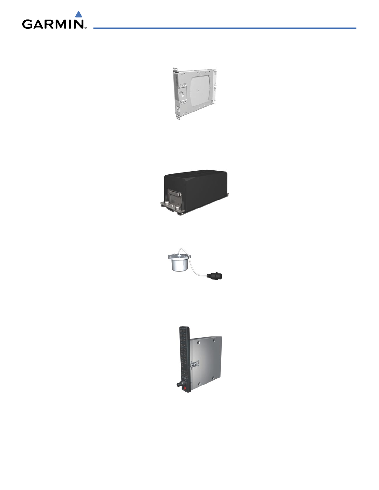
1.2 LINE REPLACEABLE UNITS (LRU)
•
GDU 1040/1044B
– The GDU 1044B features a 10.4-inch LCD display with 1024 x 768 resolution. The left
display is configured as a PFD and the right display is configured as an MFD. Both GDU 1044Bs link and
display all functions of the G1000 system during flight. The displays communicate with each other through a
High-Speed Data Bus (HSDB) Ethernet connection. Each display is also paired via an Ethernet connection with
a GIA 63 or 63W Integrated Avionics Unit. Systems using the Honeywell KAP 140 Autopilot System use the
GDU 1040, which employs the same features as the GDU 1044B without the controls for the Garmin GFC 700
Automatic Flight Control System (AFCS)
•
GIA 63/63W
(2) – Functions as the main communication hub, linking all LRUs with the PFD. Each GIA 63/
63W contains a GPS receiver, VHF COM/NAV/GS receivers, a flight director (FD) and system integration
microprocessors. The GIA 63W contains a GPS WAAS receiver. Each GIA is paired with a respective GDU
1040/1044B display through Ethernet. The GIAs are not paired together and do not communicate with each
other directly.
•
GDC 74A
(1) – Processes data from the pitot/static system as well as the OAT probe. This unit provides
pressure altitude, airspeed, vertical speed and OAT information to the G1000 system, and it communicates with
the GIA 63/63W, GDU 1040/1044B, and GRS 77, using an ARINC 429 digital interface. The GDC 74A also
interfaces directly with the GTP 59.
190-00498-03 Rev. A
Garmin G1000 Pilot’s Guide for Cessna Nav III
1-3
SYSTEM OVERVIEW
•
GEA 71
(1) – Receives and processes signals from the engine and airframe sensors. This unit communicates
with both GIA 63/63Ws using an RS-485 digital interface.
•
GRS 77
(1) – Provides aircraft attitude and heading information via ARINC 429 to both the GDU 1040/1044B
and the GIA 63/63W. The GRS 77 contains advanced sensors (including accelerometers and rate sensors)
and interfaces with the on-side GMU 44 to obtain magnetic field information, with the GDC 74A to obtain
air data, and with both GIAs to obtain GPS information. AHRS modes of operation are discussed later in this
document.
•
GMU 44
(1) – Measures local magnetic field. Data is sent to the GRS 77 for processing to determine aircraft
magnetic heading. This unit receives power directly from the GRS 77 and communicates with the GRS 77,
using an RS-485 digital interface.
•
GMA 1347
– The GMA 1347 Audio Panel integrates NAV/COM digital audio, intercom system and marker
beacon controls. The GMA 1347 also controls manual display reversionary mode (red
DISPLAY BACKUP
button) and is installed between the MFD and the PFD. The GMA 1347 communicates with both GIA 63/
63Ws using an RS-232 digital interface.

190-00498-03 Rev. A
Garmin G1000 Pilot’s Guide for Cessna Nav III
1-4
SYSTEM OVERVIEW
•
GTX 33
(1) – The GTX 33 is a solid-state, Mode-S transponder that provides Modes A, C and S operation. The
GTX 33 is controlled through the PFD and communicates with both GIA 63/63Ws through an RS-232 digital
interface.
•
GDL 69A
(1) – A satellite radio receiver that provides real-time weather information to the G1000 MFD (and,
indirectly, to the inset map of the PFD) as well as digital audio entertainment. The GDL 69A communicates
with the MFD via HSDB connection. A subscription to the XM Satellite Radio service is required to enable the
GDL 69A capability.
•
GDL 90
(1) – A digital data link transceiver designed to transmit, receive and decode ADS-B messages. It
broadcasts aircraft position, velocity, projected track, altitude, and flight identification to other equipped aircraft
in the vicinity, as well as to FAA ground stations.
•
GSA 81
(3), and
GSM 85
(3) – The GSA 81 servos are used for the automatic control of roll, pitch, and pitch
trim. These units interface with each GIA 63/63W.
The GSM 85 servo mount is responsible for transferring the output torque of the GSA 81 servo actuator to the
mechanical flight-control surface linkage.
190-00498-03 Rev. A
Garmin G1000 Pilot’s Guide for Cessna Nav III
1-5
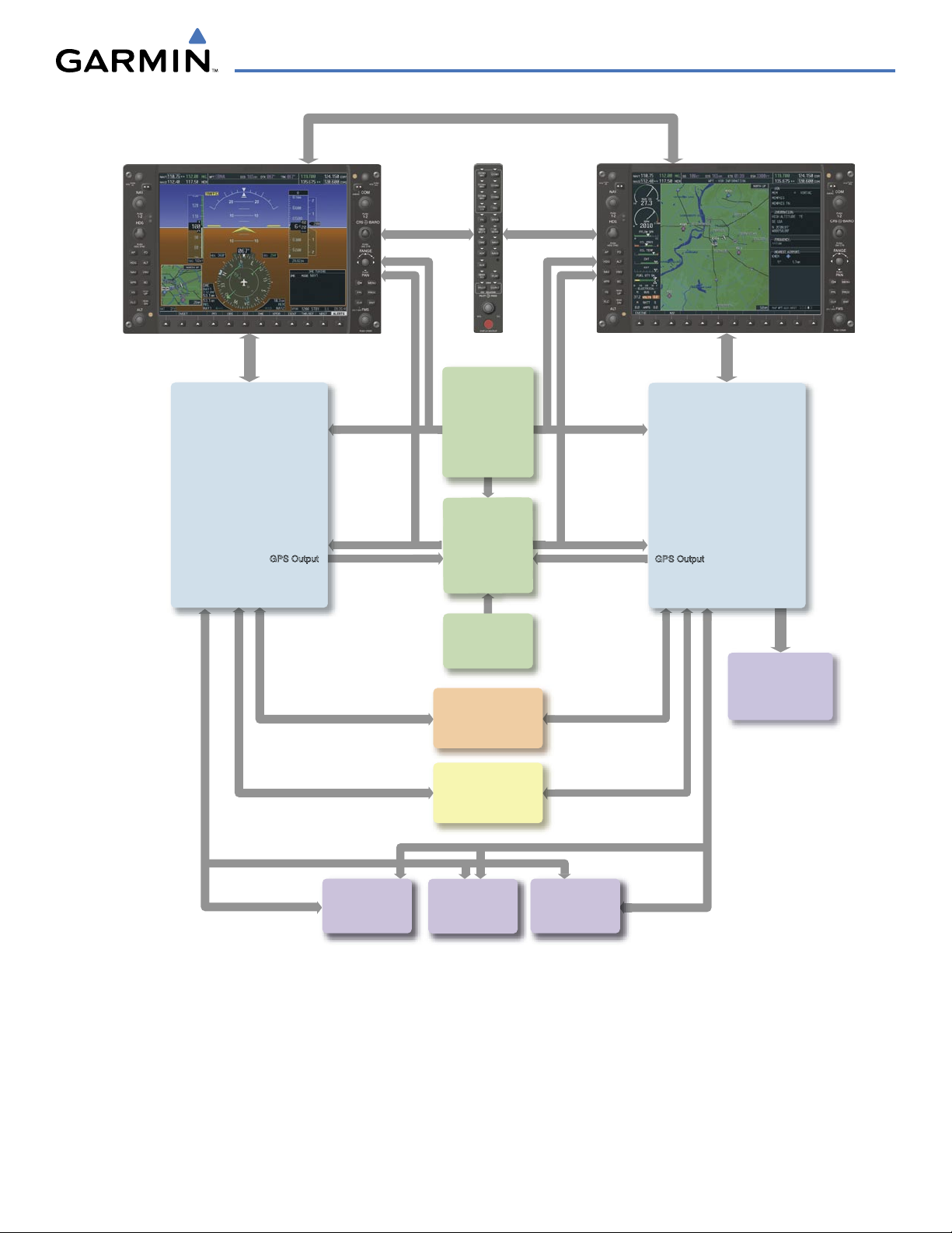
SYSTEM OVERVIEW
Figure 1-1 Basic G1000 System
No. 1 GIA 63/63W
Integrated Avionics Unit
System Inegration Processors
I/O Processors
VHF COM
VHF NAV/LOC
GPS/WAAS
Glideslope
GFC 700 Flight Director
(172S, 182, & 206)
No. 2 GIA 63/63W
Integrated Avionics Unit
System Integration Processors
I/O Processors
VHF COM
VHF NAV/LOC
GPS/WAAS
Glideslope
GTX 33
Transponder
Reversionary
Control
GEA 71
Engine/Airframe
Unit
GDC 74A
Air Data
Computer
OAT
Airspee
d
Altitude
Ve
rtical Speed
GRS 77
AHRS
Attitude
Rate of Turn
Slip/Skid
GMU 44
Magnetometer
Heading
GPS Output
GPS Output
Reversionary
Control
GMA 1347
Audio Panel
PFD
GDU 1040 or
GDU 1044B*
Honeywell
KAP 140
Autopilot
MFD
GDU 1040 or
GDU 1044B*
The GDU 1040 is available in systems using the Honeywell KAP
140 Autopilot. The GDU 1044B is
available in systems using the Garmin GFC 700 Automatic Flight Control System
.
*
GSA 81
Pitch Trim
Autopilot Calculations
(172S, 182, & 206)
GSA 81
Pitch Servo
Autopilot Calculations
(172S, 182, & 206)
GSA 81
Roll Servo
Autopilot Calculations
(172S, 182, & 206)
190-00498-03 Rev. A
Garmin G1000 Pilot’s Guide for Cessna Nav III
1-6
SYSTEM OVERVIEW
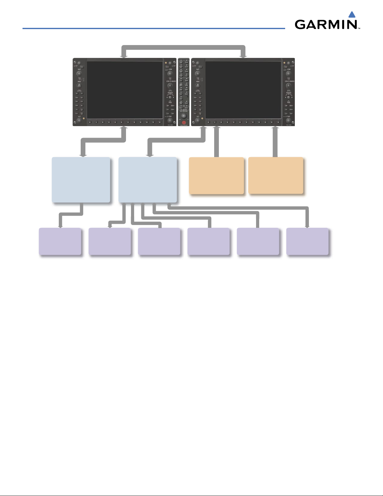
No. 2 GIA 63/63W
Integrated Avionics Unit
System Integration Processors
I/O Processors
VHF COM
VHF NAV/LOC
GPS
Glideslope
L3
Stormscope
Lightning Strike and
Thunderstorm Detection
Honeywell
KR 87
ADF Receiver
Honeywell
KN 63
DME
GDL 69/69A
Data Link
Weather Data
Digital Audio Entertainment
CO Guardian
Carbon Monoxide
Detection
Honeywell
KTA 870
Traffic Avoidance
System
ELT
Emergency Locator
Tr
ansmitter
No. 1 GIA 63/63W
Integrated Avionics Unit
System Integration Processors
I/O Processors
VHF COM
VHF NAV/LOC
GPS
Glideslope
GFC 700 Flight Director
GDL 90
Data Link
ADS-B Traffic Data
Figure 1-2 G1000 Optional/Additional Equipment
190-00498-03 Rev. A
Garmin G1000 Pilot’s Guide for Cessna Nav III
1-7
SYSTEM OVERVIEW
1.3 G1000 CONTROLS
NOTE:
The Audio Panel (GMA 1347) and AFCS controls are described in the CNS & Audio Panel and AFCS
sections respectively.
The G1000 system controls are located on the PFD and MFD bezels and audio panel. The controls for the PFD
and MFD are discussed within the following pages of this section.
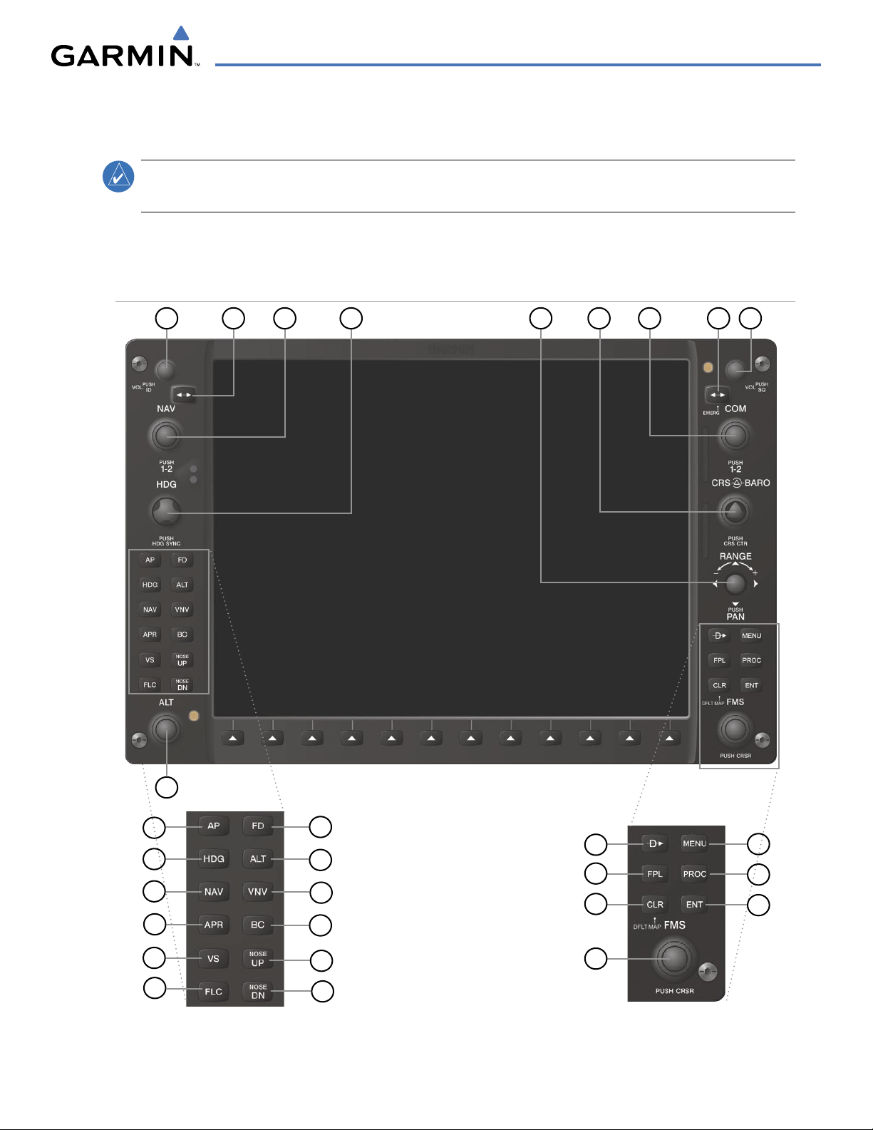
PFD/MFD CONTROLS
Figure 1-3 PFD/MFD Controls
42
1
6
5
7
9
8
3
17
12
13
11
10
27
25
24
28
16
15
14
20
21
19
23
18
22
26
29
GFC 700 AFCS Only

190-00498-03 Rev. A
Garmin G1000 Pilot’s Guide for Cessna Nav III
1-8
SYSTEM OVERVIEW
PFD and MFD controls function the same.
1
NAV VOL/ID Knob
– Controls the NAV audio level. Press to toggle the Morse code identifier ON and OFF.
Volume level is shown in the field as a percentage.
2
NAV Frequency Transfer Key
– Transfers the standby and active NAV frequencies.
3
Dual
NAV Knob
– Tunes the MHz (large knob) and kHz (small knob) standby frequencies for the NAV
receiver. Press to toggle the tuning cursor (light blue box) between the NAV1 and NAV2 fields.
4
Heading Knob
– Turn to manually select a heading on the HSI. When pressed, it synchronizes the heading
bug with the compass lubber line. Selected Heading provides the heading reference to the Flight Director
while operating in Heading Select mode.
5
Joystick
– Changes the map range (distance top to bottom of map display) when rotated. Activates the map
pointer when pressed.
6
CRS/BARO Knob
– The large
knob sets the altimeter barometric pressure and the small
knob adjusts the
course. The course is only adjustable when the HSI is in VOR1, VOR2, or OBS/SUSP mode. Pressing this
knob centers the CDI on the currently selected VOR. Selected Course provides course reference to the Flight
Director when operating in Navigation and Approach modes.
7
Dual COM Knob
– Tunes the MHz (large knob) and kHz (small knob) standby frequencies for the COM
transceiver. Pressing this knob toggles the tuning cursor (light blue box) between the COM1 and COM2
fields.
8
COM Frequency Transfer Key
– Transfers the standby and active COM frequencies. Pressing and holding
this key for two seconds automatically tunes the emergency frequency (121.5 MHz) in the active frequency
field.
9
COM
VOL/SQ Knob
– Controls COM audio level. Audio volume level is shown in the field as a percentage.
Pressing this knob turns the COM automatic squelch ON and OFF.
10
Direct-to Key
– Allows the user to enter a destination waypoint and establish a direct course to the selected
destination (specified by the identifier, chosen from the active route, or taken from the map pointer
position).
11
FPL Key
– Displays the active Flight Plan Page for creating and editing the active flight plan, or for accessing
stored flight plans.
12
CLR
Key (DFLT MAP)
– Erases information, cancels an entry, or removes page menus. To display the
Navigation Map Page immediately, press and hold
CLR
(MFD only).
13
Dual FMS Knob
– Used to select the page to be viewed (only on the MFD). The large
knob selects a page
group (MAP, WPT, AUX, NRST), while the small
knob selects a specific page within the page group. Pressing
the small
knob turns the selection cursor ON and OFF. When the cursor is ON, data may be entered in the
different windows using the small and large
knobs. The large
knob is used to move the cursor on the page,
while the small
knob is used to select individual characters for the highlighted cursor location. When the
G1000 displays a list that is too long for the display screen, a scroll bar appears along the right side of the
display, indicating the availability of additional items within the selected category. Press the small
FMS
Knob
to activate the cursor and turn the large
FMS
Knob to scroll through the list.

190-00498-03 Rev. A
Garmin G1000 Pilot’s Guide for Cessna Nav III
1-9
SYSTEM OVERVIEW
14
MENU Key
– Displays a context-sensitive list of options. This list allows the user to access additional
features, or to make setting changes that relate to certain pages.
15
PROC Key
– Selects approaches, departures and arrivals from the flight plan. If a flight plan is used, available
procedures for the departure and/or arrival airport are automatically suggested. If a flight plan is not used,
the desired airport and the desired procedure may be selected. This key selects IFR departure procedures
(DPs), arrival procedures (STARs) and approaches (IAPs) from the database and loads them into the active
flight plan.
16
ENT Key
– Accepts a menu selection or data entry. This key is used to approve an operation or complete
data entry. It is also used to confirm selections and information entries.
17
Dual
ALT Knob
– Sets the selected altitude in the box located above the Altimeter. The
large
knob selects
the thousands, while the small
knob selects the hundreds. Altitude Select is used by the Automatic Flight
Control System in certain modes, in addition to the standard G1000 Altitude Alerter function.
The following are only available with the GFC 700 AFCS.
18
AP Key
– Engages/disengages the autopilot and flight director. Pressing the
AP
Key activates the flight
director and engages the autopilot in the default pitch axis and roll axis modes. Pressing the
AP
Key again
disengages the autopilot and deactivates the flight director.
19
HDG Key
– Selects/deselects Heading Select Mode.
20
NAV Key
– Selects/deselects Navigation Mode.
21
APR Key
– Selects/deselects Approach Mode.
22
VS Key
– Selects/deselects Vertical Speed Mode.
23
FLC Key
– Selects/deselects Flight Level Change Mode.
24
FD Key
– Activates/deactivates the flight director only. Pressing the
FD
Key turns on the flight director in the
default pitch axis and roll axis modes. Pressing the
FD
Key again deactivates the flight director and removes
the command bars, unless the autopilot is engaged. If the autopilot is engaged, the
FD
Key is disabled.
25
ALT Key
– Selects/deselects Altitude Hold Mode.
26
VNV Key
– Selects/deselects Vertical Navigation Mode.
27
BC Key
– Selects/deselects Back Course Mode.
28 29
NOSE UP/NOSE DN Keys
– Controls the active pitch reference for the Pitch Hold, Vertical Speed, and
Flight Level Change modes.
190-00498-03 Rev. A
Garmin G1000 Pilot’s Guide for Cessna Nav III
1-10
SYSTEM OVERVIEW
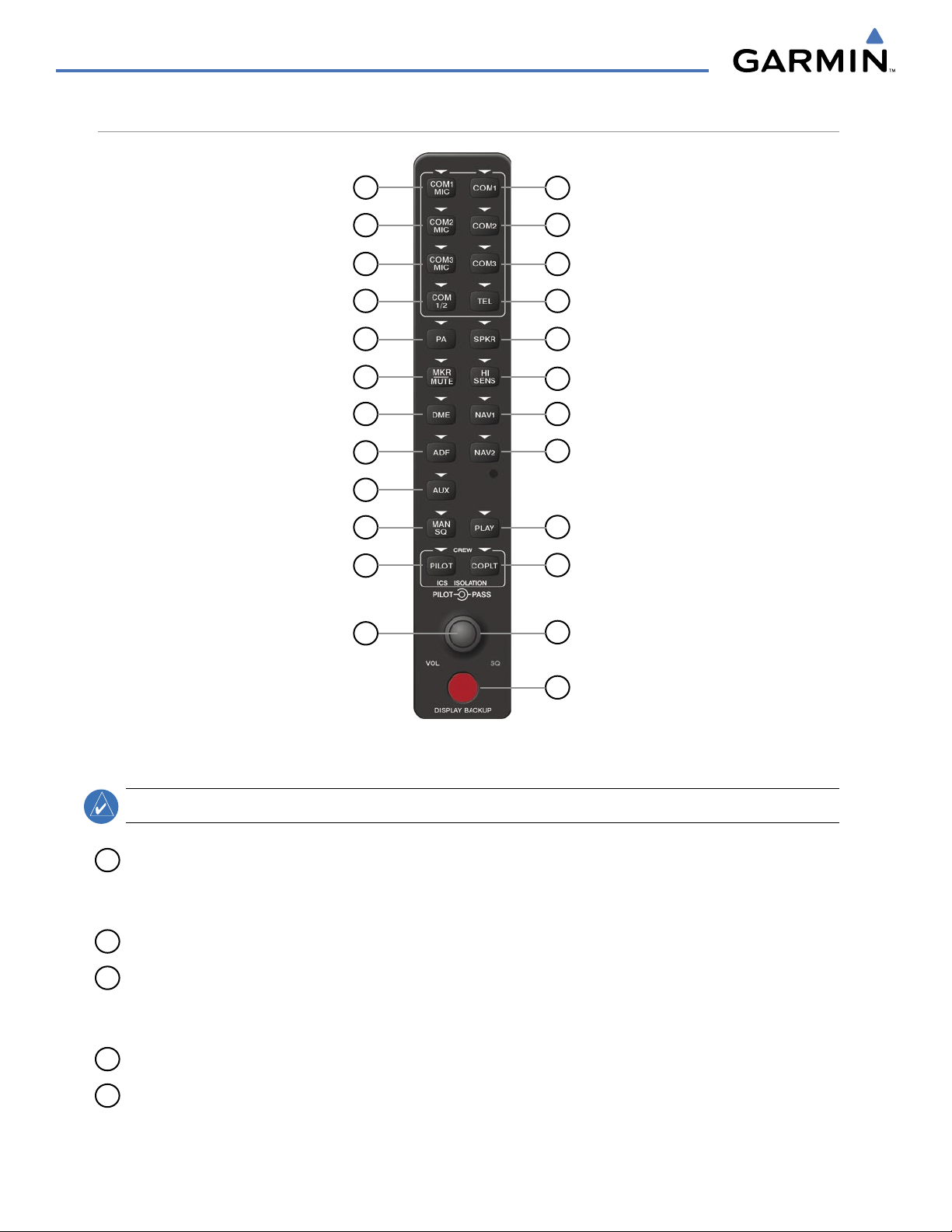
AUDIO PANEL CONTROLS
Figure 1-4 Audio Panel Controls (GMA 1347)
17
18
15
13
11
9
20
7
5
3
1
14
2
16
4
6
8
10
12
22
24
23
21
19
NOTE:
When a key is selected, a triangular annunciator above the key is illuminated.
1
COM1 MIC
– Selects the #1 transmitter for transmitting. COM1 receive is simultaneously selected when
this key is pressed allowing received audio from the #1 COM receiver to be heard. COM2 receiver audio
can be added by pressing the COM2 Key.
2
COM1
– When selected, audio from the #1 COM receiver can be heard.
3
COM2 MIC
– Selects the #2 transmitter for transmitting. COM2 is simultaneously selected when this key
is pressed allowing received audio from the #2 COM receiver to be heard. COM2 can be deselected by
pressing the COM2 Key, or COM1 can be added by pressing the COM1 Key.
4
COM2
– When selected, audio from the #2 COM receiver can be heard.
5
COM3 MIC
– Not used on Cessna Nav III aircraft.

190-00498-03 Rev. A
Garmin G1000 Pilot’s Guide for Cessna Nav III
1-11
SYSTEM OVERVIEW
6
COM3
– Not used on Cessna Nav III aircraft.
7
COM 1/2
– Split COM is disabled on Cessna Nav III aircraft.
8
TEL
– Not used on Cessna Nav III aircraft.
9
PA
– Selects the Passenger Address system. The selected COM transmitter is deselected when the PA Key
is pressed. The Passenger Address system is disabled on the Cessna 172R/S.
10
SPKR
– Selects and deselects the cabin speaker. COM and NAV receiver audio can be heard on the
speaker.
11
MKR/MUTE
– Mutes the currently received marker beacon receiver audio. Unmutes when new marker
beacon audio is received. Also, stops play of the clearance recorder.
12
HI SENS
– Press to increase marker beacon receiver sensitivity. Press again to return to normal.
13
DME
– Pressing turns DME audio on or off.
14
NAV1
– When selected, audio from the #1 NAV receiver can be heard.
15
ADF
– Pressing turns on or off the audio from the ADF receiver.
16
NAV2
– When selected, audio from the #2 NAV receiver can be heard.
17
AUX
– Not used on Cessna Nav III aircraft.
18
MAN SQ
– Press to enable manual squelch for the intercom. When active, press the PILOT Knob to
illuminate ‘SQ’. Turn the PILOT/PASS Knobs to adjust squelch.
19
PLAY
– Press once to play the last recorded audio.
Pressing the PLAY Key during play begins playing the
previously recorded memory block. Each subsequent press of the PLAY Key begins playing the next previously
recorded block
. Press the MKR/MUTE Key to stop play.
20
PILOT
– Pressing selects the pilot intercom isolation. Press again to deselect pilot isolation.
21
COPLT
– Pressing selects the copilot intercom isolation. Press again to deselect copilot isolation.
22
PILOT Knob
– Press to switch between volume and squelch control as indicated by the ‘VOL’ or ‘SQ’ being
illuminated. Turn to adjust intercom volume or squelch. The MAN SQ Key must be selected to allow
squelch adjustment.
23
PASS Knob
– Turn to adjust Copilot/Passenger intercom volume or squelch. The MAN SQ Key must be
selected to allow squelch adjustment.
24
Reversionary Mode Button
– Pressing manually selects Reversionary Mode.

190-00498-03 Rev. A
Garmin G1000 Pilot’s Guide for Cessna Nav III
1-12
SYSTEM OVERVIEW
1.4 SECURE DIGITAL (SD) CARDS
NOTE:
Ensure the G1000 System is powered off before inserting an SD card.
NOTE:
Refer to Appendix B for instructions on updating databases.
The PFD and MFD data card slots use Secure Digital (SD) cards and are located on the upper right side of the
display bezels. Each display bezel is equipped with two SD card slots. SD cards are used for aviation database
and system software updates as well as terrain database storage.
Installing an SD card:
1) Insert the SD card in the SD card slot, pushing the card in until the spring latch engages. The front of the card
should remain flush with the face of the display bezel.
2) To eject the card, gently press on the SD card to release the spring latch.
Figure 1-5 Display Bezel SD Card Slots
SD Card Slots
190-00498-03 Rev. A
Garmin G1000 Pilot’s Guide for Cessna Nav III
1-13
SYSTEM OVERVIEW
1.5 SYSTEM POWER-UP
NOTE:
See the Aircraft Flight Manual (AFM) for specific procedures concerning avionics power application
and emergency power supply operation.
NOTE:
Refer to Appendix A for system-specific annunciations and alerts.
The G1000 System is integrated with the aircraft electrical system and receives power directly from electrical
busses. The G1000 PFD, MFD, and supporting sub-systems include both power-on and continuous built-in test
features that exercise the processor, RAM, ROM, external inputs, and outputs to provide safe operation.
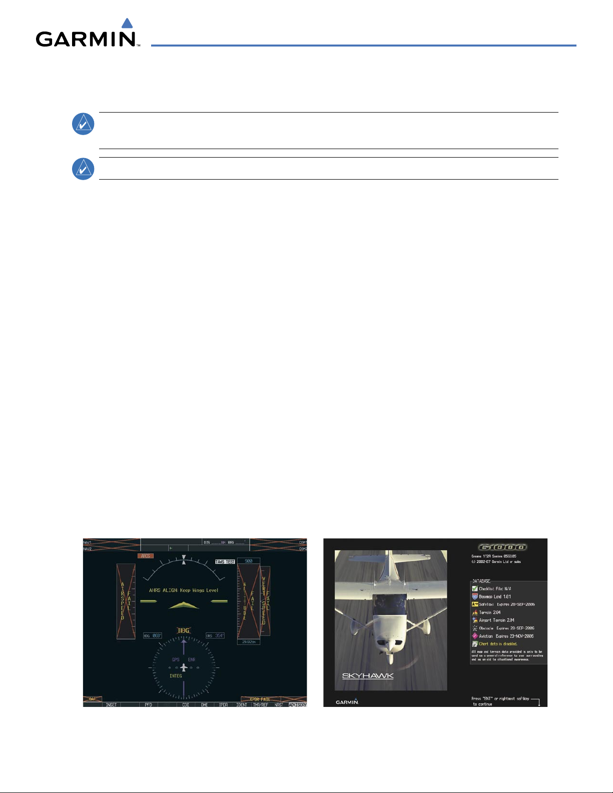
During system initialization, test annunciations are displayed, as shown in Figure 1-6. All system annunciations
should disappear typically within the first minute of power-up. Upon power-up, key annunciator lights also
become momentarily illuminated on the Audio Panel.
On the PFD, the AHRS begins to initialize and displays “AHRS ALIGN: Keep Wings Level”. The AHRS should
display valid attitude and heading fields typically within the first minute of power-up. The AHRS can align itself
both while taxiing and during level flight.
When the MFD powers up, the splash screen (Figure 1-7) displays the following information:
• System version
• Copyright
• Land database name and version
• Obstacle database name and version
• Terrain database name and version
• Aviation database name, version, and effective dates
• SafeTaxi database version and effective dates
• Chartview or FliteCharts database version and
effective dates
Current database information includes valid operating dates, cycle number, and database type. When this
information has been reviewed for currency (to ensure that no databases have expired), the pilot is prompted to
continue.
Pressing the
ENT Key (or right-most softkey) acknowledges this information, and the Navigation Map Page is
displayed upon pressing the key a second time. When the system has acquired a sufficient number of satellites to
determine a position, the aircraft’s current position is shown on the Navigation Map Page.
Figure 1-6 PFD Initialization
Figure 1-7 MFD Power-Up Splash Screen (172R shown)
190-00498-03 Rev. A
Garmin G1000 Pilot’s Guide for Cessna Nav III
1-14
SYSTEM OVERVIEW
1.6 SYSTEM OPERATION
NOTE:
In normal operating mode, backlighting can only be adjusted from the PFD. In reversionary mode, it
can be adjusted from the remaining display.
The displays are connected together via a single Ethernet bus for high-speed communication.
Each IAU is
connected to a single display, as shown in Figure 1-1. This allows the units to share information, enabling true system
integration.
. This section discusses normal and reversionary G1000 display operation, as well as the various AHRS
modes and G1000 System Annunciations.
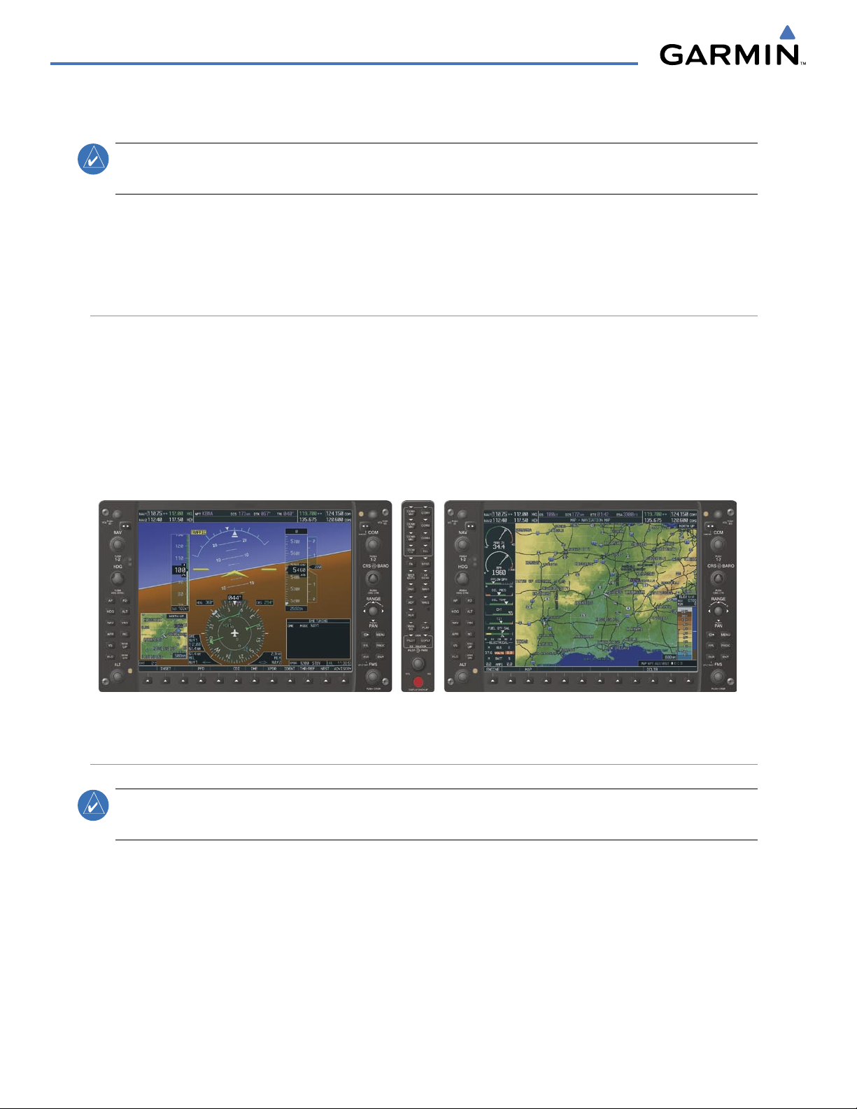
NORMAL DISPLAY OPERATION
In normal operating mode, the PFD presents graphical flight instrumentation (attitude, heading, airspeed,
altitude, vertical speed), replacing the traditional flight instrument cluster (see the Flight Instruments Section
for more information).
The MFD normally displays a full-color moving map with navigation information (see the Flight Management
Section), while the left portion of the MFD is dedicated to the Engine Indication System (EIS; see the EIS
Section).
Both displays offer control for COM and NAV frequency selection.
Figure 1-8 Normal Mode
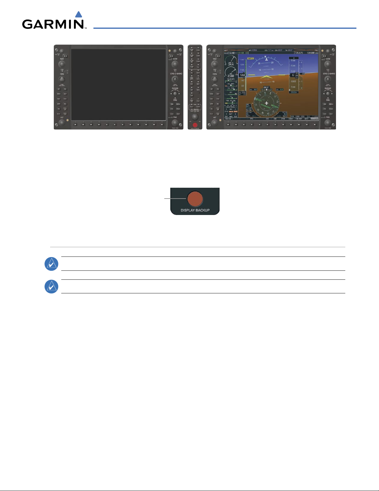
REVERSIONARY DISPLAY OPERATION
NOTE:
The G1000 System alerts the pilot when backup paths are utilized by the LRUs. Refer to Appendix A
for further information regarding system-specific alerts.
In the event of a display failure, the G1000 System automatically switches to reversionary (backup) mode. In
reversionary mode, all important flight information is presented on the remaining display in the same format
as in normal operating mode.
If a display fails, the appropriate IAU Ethernet interface to the display is cut off. Thus, the IAU can no longer
communicate with the remaining display (refer to Figure 1-1), and the NAV and COM functions provided to
the failed display by the IAU are flagged as invalid on the remaining display. The system reverts to backup
paths for the AHRS, ADC, Engine/Airframe Unit, and Transponder, as required. The change to backup paths is
completely automated for all LRUs and no pilot action is required.
190-00498-03 Rev. A
Garmin G1000 Pilot’s Guide for Cessna Nav III
1-15
SYSTEM OVERVIEW
Figure 1-9 Reversionary Mode (Failed PFD)
If the system fails to detect a display problem, reversionary mode may be manually activated by pressing
the Audio Panel’s red
DISPLAY BACKUP
button (refer to the Audio Panel and CNS Section for further details).
Pressing this button again deactivates reversionary mode.
Figure 1-10 DISPLAY BACKUP Button
Pressing the
DISPLAY BACKUP
button activates/deactivates
reversionary mode
AHRS OPERATION
NOTE:
Refer to Appendix A for specific AHRS alert information.
NOTE:
Aggressive maneuvering while AHRS is not operating normally may degrade AHRS accuracy.
The Attitude and Heading Reference System (AHRS) performs attitude, heading, and vertical acceleration
calculations for the G1000 System, utilizing GPS, magnetometer, and air data in addition to information
from its internal sensors. Attitude and heading information are updated on the PFD while the AHRS receives
appropriate combinations of information from the external sensor inputs.
Loss of GPS, magnetometer, or air data inputs is communicated to the pilot by message advisory alerts. Any
failure of the internal AHRS inertial sensors results in loss of attitude and heading information (indicated by red
‘X’ flags over the corresponding flight instruments).
190-00498-03 Rev. A
Garmin G1000 Pilot’s Guide for Cessna Nav III
1-16
SYSTEM OVERVIEW
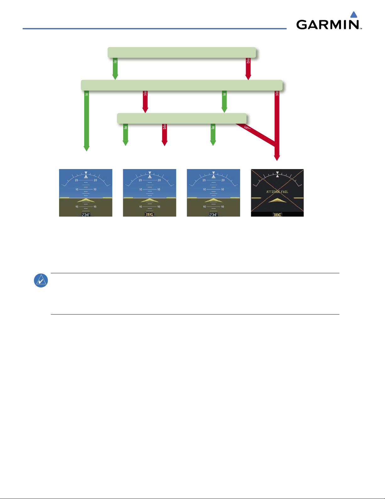
Attitude/Heading Invalid
AHRS
no-GPS
Mode
AHRS Normal
Operation
AHRS no-
Mag Mode
AHRS no-Mag/
no-Air Mode
Heading Invalid
available
available
unavailable
una
v
ail
ab
le
available
unavailable
unavailable
available
Airspeed Data
Magnetometer
unavailable
available
GPS
Figure 1-11 AHRS Operation
GPS INPUT FAILURE
NOTE:
In-flight initialization of AHRS, when operating without any valid source of GPS data and at true
air speed values greater than approximately 200 knots, is not guaranteed. Under these rare conditions, it
is possible for in-flight AHRS initialization to take an indefinite amount of time which would result in an
extended period of time where valid AHRS outputs are unavailable.
Two GPS inputs are provided to the AHRS. If GPS information from one of the inputs fails, the AHRS uses
the remaining GPS input and an alert message is issued to inform the pilot. If both GPS inputs fail, the AHRS
can continue to provide attitude and heading information to the PFD as long as magnetometer and airspeed
data are available and valid.
MAGNETOMETER FAILURE
If the magnetometer input fails, the AHRS continues to output valid attitude information; however, the
heading output on the PFD is flagged as invalid with a red ‘X’.
AIR DATA INPUT FAILURE
Failure of the air data input has no affect on the AHRS output while AHRS is receiving valid GPS
information. Invalid/unavailable airspeed data in addition to GPS failure results in loss of all attitude and
heading information.

190-00498-03 Rev. A
Garmin G1000 Pilot’s Guide for Cessna Nav III
1-17
SYSTEM OVERVIEW
G1000 SYSTEM ANNUNCIATIONS
NOTE:
For a detailed description of all annunciations and alerts, refer to Appendix A. Refer to the Pilot’s
Operating Handbook (POH) for additional information regarding pilot responses to these annunciations.
When an LRU or an LRU function fails, a large red “X” is typically displayed on windows associated with
the failed data (Figure 1-12 displays all possible flags and responsible LRUs). Upon G1000 power-up, certain
windows remain invalid as equipment begins to initialize. All windows should be operational within one
minute of power-up. If any window remains flagged, the G1000 system should be serviced by a Garmin-
authorized repair facility.
Figure 1-12 G1000 System Failure Annunciations
GDC 74A Air
Data Computer
GTX 33 Transponder
OR
GIA 63/W Integrated
Avionics Units
GDC 74A Air
Data Computer
GEA 71 Engine
Airframe Unit
OR
GIA 63/W
Integrated
Avionics Unit
GIA 63/W Integrated
Avionics Units
GRS 77 AHRS
OR
GMU 44
Magnetometer
GIA 63/W
Integrated
Avionics Units
GIA 63/W
Integrated
Avionics Units
SOFTKEY FUNCTION
The softkeys are located along the bottoms of the displays. The softkeys shown depend on the softkey level
or page being displayed. The bezel keys below the softkeys can be used to select the appropriate softkey. When
a softkey is selected, its color changes to black text on gray background and remains this way until it is turned
off, at which time it reverts to white text on black background.
Softkey Names
(Displayed)
Figure 1-13 Softkeys (Second-Level PFD Configuration)
Bezel-Mounted
Softkeys (Press)
Softkey
On

190-00498-03 Rev. A
Garmin G1000 Pilot’s Guide for Cessna Nav III
1-18
SYSTEM OVERVIEW
PFD SOFTKEYS
The
CDI
,
IDENT
,
TMR/REF
,
NRST,
and
ALERTS
softkeys undergo a momentary change to black text on
gray background and automatically switch back to white text on black background when selected.
The PFD softkeys provide control over flight management functions, including GPS, NAV, terrain, traffic,
and lightning (optional). Each softkey sublevel has a
BACK Softkey which can be selected to return to the
previous level. The ALERTS Softkey is visible at all softkey levels (label changes if messages are issued).
INSET
Displays Inset Map in PFD lower left corner
OFF
Removes Inset Map
DCLTR (3)
Selects desired amount of map detail; cycles through declutter levels:
DCLTR (No Declutter): All map features visible
DCLTR-1: Declutters land data
DCLTR-2: Declutters land and SUA data
DCLTR-3: Removes everything except for the active flight plan
TRAFFIC
Displays traffic information on Inset Map
TOPO
Displays topographical data (e.g., coastlines, terrain, rivers, lakes) and
elevation scale on Inset Map
TERRAIN
Displays terrain information on Inset Map
STRMSCP
Displays Stormscope® information on Inset Map
NEXRAD
Displays NEXRAD weather and coverage information on Inset Map (optional
feature)
XM LTNG
Displays XM lightning information on Inset Map (optional feature)
PFD
Displays second-level softkeys for additional PFD configurations
DFLTS
Resets PFD to default settings, including changing units to standard
WIND
Displays softkeys to select wind data parameters
OPTN 1
Wind direction arrows with headwind and crosswind components
OPTN 2
Wind direction arrow and speed
OPTN 3
Wind direction arrow with direction and speed
OFF
Information not displayed
DME
Displays the DME Information Window
BRG1
Cycles the Bearing 1 Information Window through NAV1, GPS/ waypoint
identifier and GPS-derived distance information, and ADF/frequency
HSI FRMT
Provides access to the HSI formatting softkeys
360 HSI
Displays the HSI in a 360 degree view
ARC HSI
Displays the HSI as an arc
BRG2
Cycles the Bearing 2 Information Window through NAV2 or GPS waypoint
identifier and GPS-derived distance information, and ADF/frequency.
Loading...