


No part of this document may be reproduced in any form or by any means without the express written consent of UPS Aviation Technologies, Inc.
UPS Aviation Technologies, Inc., II Morrow, and Apollo are trademarks of UPS Aviation Technologies, Inc.
© 2001 by UPS Aviation Technologies, Inc. All rights reserved. Printed in the U.S.A.
UPS Aviation Technologies, Inc.
2345 Turner Road, S.E. Salem, OR 97302
U.S.A. Toll Free |
800.525.6726 |
Canada Toll Free |
800.654.3415 |
International |
503.391.3411 |
FAX |
503.364.2138 |
Visit our web page at http://www.upsat.com
Send comments about this manual by email to: techpubs@at.ups.com
History of Revisions
Original Release December 2001 Rev. 00
Ordering Information
To receive additional copies of the Apollo SL10 Installation Guide, order part #560-0978-00 and for the Apollo SL10 User’s Guide, order part #560-0973-00a.
|
UPS Aviation Technologies |
|
|
SL10 Series Audio Selector Panel and Intercom System |
|
|
User’s Guide |
|
|
Table of Contents |
|
Section I - General Information ...................................................... |
1 |
|
1.1 |
SCOPE ...................................................................................... |
1 |
1.2 |
Audio Selector (All models) ..................................................... |
1 |
1.2.1 Speaker Amplifier ........................................................... |
2 |
|
1.3 |
Mic Selector Switch (Fail Safe Operation) ............................... |
2 |
1.3.1 Swap Mode (Switch from Com 1 to Com 2 remotely).... |
3 |
|
1.4 |
Split Mode................................................................................. |
3 |
1.5 |
Intercom .................................................................................... |
3 |
1.5.1 Volume Control, Monaural (SL10M SL10) .................... |
3 |
|
1.5.2 Volume Control, Stereo, (SL10S, SL10MS) ................... |
4 |
|
1.5.3Adjusting the VOX-Squelch control, Monaural (SL10, SL10M) 4
1.5.4Adjusting the VOXSquelch control, Stereo (SL10S,
SL10MS)........................................................................................ |
5 |
||
1.5.5 |
Intercom Modes (All versions)........................................ |
5 |
|
1.5.6 |
Push to talk intercom mode ............................................. |
7 |
|
1.6 |
Marker Beacon (SL10M, SL10M-S.......................................... |
8 |
|
1.6.1 |
Middle Marker Sense ...................................................... |
8 |
|
1.6.2 |
External Marker Lights (SL10, SL10S)........................... |
8 |
|
1.6.3 |
Receiver Sensitivity......................................................... |
9 |
|
Section IIWarranty and Service ................................................. |
10 |
||
2.1 |
Warranty ................................................................................. |
10 |
|
2.2 |
Factory Service ....................................................................... |
10 |
|
UPS Aviation Technologies
SL10 Series Audio Selector Panel and Intercom System
User’s Guide
UPS Aviation Technologies
SL10 Series Audio Selector Panel and Intercom System
User’s Guide
Section I - General Information
1.1SCOPE
This section provides detailed operating instructions for the UPS Aviation Technologies SL10, SL10S, SL10M, SL10M-S, SL10C, SL10S-C, SL10M-C, and SL10M-S-C Audio Selector Panel/Intercom Systems. Please read it carefully before using the equipment so that you can take full advantage of its capabilities.
This section is divided into four sections covering the basic operating areas of the SL10 systems. They are: Audio Selector, Transceiver Selection, Intercom, and Marker Beacon Receiver (SL10M and SL10MS only).
1.2Audio Selector (All models)
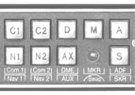
Through the use of two momentary and seven latched, push-button, back-lit switches, it is possible to select any or all receiver audio. C1 and C2 are momentary switches.
When selected, an internal backlight will illuminate indicating which audio source is selected. Because the rotary switch controls what transceiver is being
heard by the pilot and copilot (the crew), "Cl" (Com 1) and "C2" (Com 2) push-buttons are of the momentary type and do not remain in when selected. This is also part of the "auto function." You will always hear the audio from the transceiver that is selected by the rotary mic selector switch.
The users can identify which receivers are selected by noting which push-button switches are illuminated. Push buttons labeled Nl (Nav 1), N2 (Nav 2), D (DME), M (Marker), A (ADF), AX (auxiliary), and S (Speaker) are "latched" type switches. When one of these buttons is pressed, it will stay in the "in" position. Press the switch again and it be in the "out" position and remove that receiver from the audio. While selected, the switch will also be annunciated by an internal lamp. NOTE: In Split Mode, no pushbuttons will be active. The only audio selected is the com 1 and 2, as indicated by their respective lamps.
Page 1
 Loading...