


 Loading...
Garmin 6008, 7212, 7215, 6212, 6012 User Manual
...GPSMAP® 6000/7000 Series Installation Instructions
WARNING
See the Important Safety and Product Information guide in the product box for product warnings and other important information.
Caution
Always wear safety goggles, ear protection, and a dust mask when drilling, cutting, or sanding.
Notice
When drilling or cutting, always check what is on the opposite side of the surface to avoid damaging your boat.
The GPSMAP 6000/7000 series chartplotter and GPS 17x antenna must be properly installed according to the following instructions. You need the appropriate fasteners, tools, and mounts listed in each section. These items are available at most marine dealers.
Contact Garmin® Product Support if you have any questions while installing your GPSMAP 6000/7000 series chartplotter. In the USA, go to www.garmin.com/support, or contact Garmin USA by phone at (913) 397.8200 or (800) 800.1020. In the UK, contact Garmin (Europe) Ltd. by phone at 0808 2380000. In Europe, go to www.garmin.com/support and click Contact Support for in-country support information, or contact Garmin (Europe) Ltd. by phone at +44 (0) 870.8501241.
Before installing your GPSMAP6000/7000 series chartplotter, confirm that the package contains the items listed on the box. If any parts are missing, contact your Garmin dealer immediately.
Product Registration
Help us better support you by completing our online registration today. Go to http://my.garmin.com. Keep the original sales receipt, or a photocopy, in a safe place.
For future reference, write the serial numbers assigned to your GPSMAP 6000/7000 series chartplotter and GPS 17x in the space provided. The serial numbers are located on a sticker on the back of each device.
Chartplotter serial number:
GPS 17x serial number:
To install the GPSMAP 6000/7000 series chartplotter, you must:
1.Mount the GPSMAP 6000/7000 series chartplotter (page 2).
2.Mount the GPS antenna (page 4).
3.Connect the GPSMAP 6000/7000 series chartplotter to power (page 7).
4.Connect the GPSMAP 6000/7000 series chartplotter and the GPS 17x antenna to an existing NMEA 2000 network or create a simple NMEA 2000 network (page 8).
5.Ensure that the chartplotter software is up-to-date (page 17).
The following additional installation options are not necessary in order to use the GPSMAP 6000/7000 chartplotter. They have been included for your convenience:
•Connecting the chartplotter to other Garmin Marine Network compatible devices, such as a sounder or a radar (page 9).
•Connecting the chartplotter to a GPS 17 or GPS 17 HVS antenna (page 15).
•Connecting the chartplotter to other NMEA 0183-compatible devices such as a VHF radio with DSC (page 12).
•Connecting the chartplotter to an external alarm (page 15).
•Connecting the chartplotter to a video input source, to a PC, or to an external video monitor (page 16).
June 2010 |
Part Number 190-01120-02 Rev. C |
Printed in Taiwan |
Mounting the GPSMAP 6000/7000 Series Chartplotter
You can mount the GPSMAP 6000/7000 series chartplotters using one of two methods. You can use the included bracket to bail mount the chartplotter, or you can use the included template and hardware to flush mount the chartplotter.
Mount the GPSMAP 6000/7000 series chartplotter in a location that provides a clear, glare-free view of the display and easy operation of the controls or touch screen.
Note: You cannot bail mount the GPSMAP7015/7215 chartplotters. Because of the larger size of these devices, you must flush mount a
GPSMAP 7015 or a GPSMAP 7215 chartplotter.
Bail Mounting the GPSMAP 6000/7000 Series Chartplotter
Use the included bracket to bail mount a GPSMAP 6008, 6208, 6012, 6212, 7012, or a GPSMAP 7212 chartplotter.
Tools required (not included):
•Drill and drill bits
•Pencil
•Mounting hardware (screws or nuts, washers, and bolts)
Note: The bail-mounting hardware (screws or nuts, washers, and bolts) is not included. The holes on the bail mount are 5/16 in. (7.9 mm) in diameter. Choose mounting hardware that fits the holes in the bail mount and securely attaches it to your specific mounting surface.The size of the drill bit required depends on the mounting hardware you use.
To install the bail-mount bracket:
Note: You cannot bail mount the GPSMAP7015/7215 chartplotters. Because of the larger size of these devices, you must flush mount a
GPSMAP 7015 or a GPSMAP 7215 chartplotter.
1.Using the bail mount as a template, mark the location of the four mounting holes. Be sure to leave at least 5 in. (12.7 cm) of clearance behind the 6000/7000 series chartplotter for the wiring.
NOTE: To avoid interference, mount GPSMAP 6008/6208 chartplotters 15 in. (38.1 cm), GPSMAP 6012/6212 chartplotters 16 in. (40.6 cm), and GPSMAP 7012/7212 chartplotters 25 in. (63.5 cm) from a magnetic compass.
2.Using an appropriately-sized drill bit, drill the pilot holes for your mounting hardware.
3.Secure the bail mount to the surface with screws and washers.
To install the GPSMAP 6000/7000 series chartplotter on the bail-mount bracket:
1.Loosely attach the mounting knobs to the GPSMAP 6000/7000 series chartplotter.
2.Slide the chartplotter onto the bail mount, and tighten the mounting knobs.
Mounting knob
Bail-mount bracket
Installing a GPSMAP 6000/7000 Series Chartplotter on the Bail-mount Bracket
|
GPSMAP 6000/7000 Series Installation Instructions |
Flush Mounting the GPSMAP 6000/7000 Series Chartplotter
Hardware (included):
•Flush-mount template
•Rubber gasket
•Four flush-mount nut-plates
•Four 60 mm M3 × 0.5 screws (to secure the nut plate to the mounting surface)
•Four M4 × 0.7 screws (to secure the chartplotter to the nut plate)
•Four 7 mm nylon washers (for the M4 × 0.7 screws)
Tools required (not included):
•Jigsaw
•Scissors
•Drill
•Drill bits—3/8 in. (9.5 mm), 9/32 in. (7.2 mm), and 9/64 in. (3.5 mm)
•Number 2 Phillips screwdriver
•Center punch and hammer
•File and sandpaper
1.The flush-mount template is included in the product box. Trim the template and ensure that it will fit in the location at which you want to flush mount the chartplotter.
Notes:
•Ensure that the surface on which you mount the chartplotter has enough open space behind it to accommodate the chartplotter and the connected wires. Refer to the diagram on the flush-mount template for the clearance-space needed by your chartplotter.
•Ensure that there is at least 1/2 in. (13 mm) of space on the right side of the chartplotter to access the SD card door, as indicated on the flush-mount template.
•Ensure that enough ventilation is present behind the mounting surface to create sufficient air flow to prevent the chartplotter from overheating.
•To avoid interference, mount GPSMAP 6008/6208 chartplotters 15 in. (38.1 cm), GPSMAP 6012/6212 chartplotters 16 in. (40.6 cm), GPSMAP 7012/7212 chartplotters 25 in. (63.5 cm) and 7015/7215 chartplotters 17 in. (43.2 cm) from a magnetic compass.
2.The flush-mount template has adhesive on the back. Remove the protective liner and apply the template to the location at which you want to flush mount the chartplotter.
3.Using a 3/8 in. (9.5 mm) drill bit, drill one or more of the four pilot holes inside the corner of the template to begin cutting the mounting surface.
4.Using a jigsaw, cut the mounting surface along the inside of the solid line indicated on the flush-mount template. Use a file and sandpaper to refine the size of the hole. Be very careful when cutting this hole. There is only a small amount of clearance between the case and the mounting holes.
5.Place the chartplotter in the hole and ensure that the mounting holes on the chartplotter line up with the larger 9/32 in. (7.2 mm) holes on the flush-mount template after cutting, sanding, and filing the hole. If they do not line up, mark new locations for the larger holes.
6.Using a center punch, indent the center of each of the larger 9/32 in. (7.2 mm) mounting-hole locations.
7.Using a 9/32 in. (7.2 mm) drill bit, drill the four larger holes.
8.Starting in one corner of the template, place a nut plate over the larger hole you drilled in step 7. Ensure that the smaller 9/64 in. (3.5 mm) hole on the nut plate lines up with the smaller hole on the template. If they do not line up, mark a new location for the smaller hole. Repeat this step for each corner of the template.
9.Using a center punch, indent the center of each of the smaller 9/64 in. (3.5 mm) mounting-hole locations.
10.Remove the flush-mount template from the mounting surface.
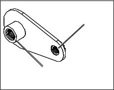
11.Starting in one corner of the mounting location, place a nut plate on the back of the mounting surface, lining up the large and small holes. The raised portion of the nut plate should fit into the larger hole.
12.Secure the nut plate to the mounting surface by fastening an included 60 mm M3 × 0.5 screw through the smaller 9/64 in. (3.5 mm) hole.
Use the 60 mm M3 × 0.5 screw to fasten the nut plate to the mounting surface
Use the 70 mm M4 × 0.7 screw to fasten the chartplotter to the nut plate
Flush-mount Nut Plate
GPSMAP 6000/7000 Series Installation Instructions |
|

70 mm M4×0.7 screw (×4)
Nut plate (×4)
60 mm M3×0.5 screw (×4)
Mounting surface


 Rubber gasket


 (4 pieces)
Flush-mounting a GPSMAP 6000 or 7000 Series Chartplotter
13.Repeat steps 11–12 for each nut plate on the remaining three corners of the mounting surface.
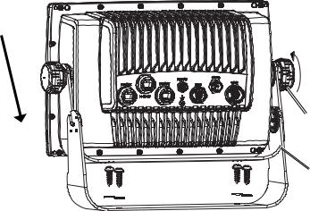
14.Install the rubber gasket on the back of the chartplotter. The top and bottom sections line up with the holes.
15.If you will not have access to the back of the chartplotter after you mount it, connect all necessary cables to the chartplotter before placing it into the cutout.
16.Place the chartplotter into the cutout.
17.Secure the chartplotter to the mounting surface using the included 70 mm M4 × 0.7 screws and 7 mm black nylon washers.
NOTE: To prevent corrosion of the metal contacts, cover unused connectors (page 17) with the attached weather caps.
18.Install the mounting covers by snapping them into place.
Mounting covers (×2)
Mounting the GPS 17x Antenna
You can surface mount the GPS 17x antenna, attach it to a standard 1 in. OD pipe-threaded-pole marine mount (14 threads-per-inch—not included), or install the antenna under fiberglass.
Select a suitable location for the GPS 17x antenna on your boat. To ensure the best reception, mount the GPS 17x antenna in a location that has a clear, unobstructed view of the sky in all directions.
•Avoid mounting the GPS 17x antenna where it is shaded by the superstructure of the boat, a radome antenna, or a mast.
•On a sailboat, avoid mounting the GPS 17x antenna high on the mast to prevent inaccurate speed readings caused by excessive heeling.
•The GPS 17x antenna provides more-stable readings when located nearer to water level.
•Mount the GPS 17x antenna at least 3 ft. (1 m) away from (preferably above) the path of any radar beam or a VHF radio antenna.
Temporarily secure the antenna in the preferred mounting location and test it for correct operation. If you experience interference with other electronics, try a different location. After you verify correct operation, permanently mount the antenna.
Tools required (not included):
•Drill and drill bits
•Screwdrivers
•Marine sealant (optional)
Better |
Best |
|
|
Good |
|
EMI |
SSBARNETT |
|
|
||
EMI (Electromagnetic Interference) |
||
from engine components |
||
Above - best |
|
|
Below - OK |
3 ft. |
|
(1 m) |
||
Radar |
||
VHF Radio Antenna |
||
GPS 17x Placement Considerations
GPSMAP 6000/7000 Series Installation Instructions
Surface-mounting the GPS 17x Antenna
1.Use the surface-mount bracket as your mounting template, using the following steps:.
•Use a center punch to mark the three screw locations on the surface.
•Use a pencil to trace the cable-hole in the center of the bracket.
•Set the surface-mount bracket aside. Do not drill through the surface-mount bracket.
2.Drill 1/8 in. (3 mm) pilot holes at the three marked locations.
Note: If you are mounting the GPS 17x on fiberglass, it is recommended to use a countersink bit to drill a clearance counterbore through the top gelcoat layer (but no deeper). This will help to avoid cracking in the gelcoat layer when the screws are tightened.
3.Use a 1 in. (25 mm) hole saw to cut the cable hole in the center.
4.Place the seal pad on the bottom of the surface-mount bracket. Make sure that the screw holes align.
5.Use the included M4 screws to attach the surface-mount bracket to the mounting surface.
|
|
|
|
GPS 17x |
|
antenna |
||
|
|
|
Surface-mount |
Rubber |
|
gasket |
||
bracket |
||
|
||
Seal pad |
|
|
Mounting |
|
|
surface |
|
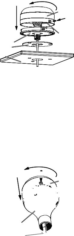
6.Route the NMEA 2000 cable through the 1 in. (25 mm) cable hole and connect it to the GPS 17x.
7.Make sure the large gasket is in place on the bottom of the GPS 17x antenna, place the antenna on the surface-mount bracket , and twist it clockwise to lock it in place .
8.Secure the antenna to the mounting bracket with the included M3 set screw .
9.Route the NMEA 2000 drop cable away from sources of electronic interference, and connect it to your NMEA 2000 network (page 8).
Pole Mounting the GPS 17x Antenna
With the pole-mount adapter attached to the GPS 17x, you can install the GPS 17x on a standard 1 in. OD pipe-threaded-pole marine mount (14 threads per inch—not included). You can run the NMEA 2000 cable through the pole or outside the pole.
To mount the GPS 17x with the cable run outside the pole:
1.Route the NMEA 2000 drop cable through the pole-mount adapter, and place the cable in the vertical slot along the base of the pole-mount adapter.
2.Thread the pole-mount adapter onto a standard 1 in. OD pipe-threaded-pole marine mount (14 threads per inch—not included). Do not overtighten the adapter.
3.Connect a NMEA 2000 drop cable to the GPS 17x antenna.
4. Place the GPS 17x antenna on the pole-mount adapter and twist it clockwise to lock it in place .
5.Secure the antenna to the adapter with the included M3 set screw .
6.(Optional) With the GPS 17x installed on the pole mount, fill the remaining gap in the vertical cable slot with a marine sealant.
7.Attach the marine mount to the boat if it is not already attached.
8.Route the cable away from sources of electronic interference, and connect it to your NMEA 2000 network (page 8).
To mount the GPS 17x with the cable run through the pole:
1.Position a standard 1 in. OD pipe-threaded-pole marine mount (14 threads per inch—not included) in the preferred location, and mark the approximate center of the pole.
2.Drill a hole using a 3/4 in. (19 mm) drill bit for the cable to pass through.
3.Fasten the marine mount to the boat.
4.Thread the pole-mount adapter onto the pole. Do not overtighten the adapter.
5.Route a NMEA 2000 drop cable through the pole and connect it to the GPS 17x antenna.


Pole-mount
adapter
Vertical cable 

 slot
slot 
GPS 17x
antenna
6.Place the GPS 17x antenna on the pole-mount adapter and twist it clockwise to lock it in place .
7.Secure the antenna to the adapter with the included M3 set screw .
8.(Optional) With the GPS 17x installed on the pole mount, fill the vertical cable slot with a marine sealant.
9.Route the NMEA 2000 drop cable away from sources of electronic interference, and connect it to your NMEA 2000 network (page 8).
GPSMAP 6000/7000 Series Installation Instructions
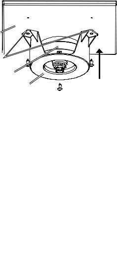
Under-deck-mounting the GPS 17x Antenna
The GPS 17x antenna can be mounted under a fiberglass surface with the adhesive pads attached to the under-deck mounting bracket.The GPS 17x will not acquire satellite signals through metal—you can only use the under-deck mount under a fiberglass surface.
1.Determine the location on the fiberglass surface where you want to mount the GPS 17x.
2.Place the adhesive pads on the under-deck mounting bracket.
3.Place the GPS 17x in the under-deck mounting bracket.
4.Adhere the under-deck mounting bracket to the mounting surface.
5.Secure the under-deck mount to the mounting surface with screws. Use extreme care to ensure that the screws do not penetrate the upper surface of the deck.
6.Connect a NMEA 2000 drop cable to the GPS 17x.
7.Route the NMEA 2000 drop cable away from sources of electronic interference, and connect it to your NMEA 2000 network (page 8).
Mounting
surface
Adhesive 
pads
GPS 17x antenna
Under-deck- mounting bracket
Installing Cables
The GPSMAP 6000/7000 series chartplotter is packaged with the following cables:
•A two-pin power cable
•A 19-pin NMEA 0183 data cable
•A 17-pin marine video cable (the GPSMAP 7015/7215 chartplotter is packaged with two different marine video cables)
•NMEA 2000 cables and connectors
Installing Locking Rings on the Cables
To help make the cable-routing process easier, the locking rings are packaged separately from the cables. Each locking ring is packaged in a small bag with a number on the label for easy identification.After you route the cables, use the following table to identify the correct locking ring for each cable:
Cable |
Connector |
Locking Ring |
|
Color |
Number |
Power |
Red |
|
|
|
|
NMEA 0183 |
Blue |
|
|
|
|
Video |
Yellow |
|
|
|
|
Video 2 |
Purple |
|
(7015/7215 only) |
|
|
Notes:
•The NMEA 2000 cables and connectors come with the locking rings pre-installed. Do not remove the locking ring from a NMEA 2000 cable while routing the cable.
•Optional Garmin Marine Network components use specialized Garmin Network cables (not included). Each network cable is also
packaged with a separate locking ring, in a bag labeled with a .Anetwork-cable specific locking ring should not be used with a
GPSMAP 6000/7000 cable.
Installing a locking ring on a cable:
1. Route the cable away from sources of electronic interference so that the cable connector is at the mounting location of the chartplotter.
GPSMAP 6000/7000 Series Installation Instructions
Loading...