


 Loading...
Instructions for Continued Airworthiness
for the Garmin G500H Installation in Eurocopter AS350
Garmin Ltd. Or its subsidiaries c/o Garmin International, Inc.
1200 E. 151st Street
Olathe, Kansas 66062 USA
Dwg. Number:
190-00792-12 Rev. 1
Confidential
This drawing and the specifications contained herein are the property of Garmin Ltd. or its subsidiaries and may not be reproduced or used in whole or in part as the basis for manufacture or sale of products without written permission.
Rev. |
Date |
Description of Change |
1 |
2/14/2014 |
Initial release. |
Note: Document was RSG P/N 16E06310001 Rev. A |
||
Table of Contents |
|
Section 01-00-00 |
|
Introduction......................................................................................................... |
4 |
CHAPTER 4.................................................................................................................................. |
5 |
Section 04-00-00 |
|
Airworthiness Limitations .................................................................................. |
5 |
CHAPTER 5.................................................................................................................................. |
6 |
Section 05-00-00 |
|
Continued Airworthiness Inspections ................................................................ |
6 |
Section 05-20-10 |
|
Continued Airworthiness Scheduled Inspections .............................................. |
9 |
Section 05-20-20 |
|
Continued Airworthiness Special Inspections ................................................... |
17 |
CHAPTER 6.................................................................................................................................. |
19 |
Section 06-00-00 |
|
Dimensions and Access ....................................................................................... |
19 |
CHAPTER 8.................................................................................................................................. |
26 |
Section 8-00-00 |
|
Weight and Balance Information ........................................................................ |
26 |
CHAPTER 12................................................................................................................................ |
27 |
Section 12-00-00 |
|
Servicing Maintenance Practices ........................................................................ |
27 |
Section 12-10-00 |
|
Return-to-Service Practices ................................................................................ |
28 |
Section 12-20-00 |
|
Calibration Requirements................................................................................... |
29 |
CHAPTER 20................................................................................................................................ |
30 |
Section 20-00-00 |
|
Standard Practices............................................................................................... |
30 |
Section 20-10-00 |
|
Torques Maintenance Practices.......................................................................... |
31 |
Section 20-30-00 |
|
Painting Maintenance Practices.......................................................................... |
35 |
Section 20-40-00 |
|
Corrosion Control Maintenance Practices.......................................................... |
36 |
Section 20-50-00 |
|
Mechanical Fastener Sealing Methods................................................................ |
39 |
Section 20-90-00 |
|
Dye Penetrant Inspection Methods..................................................................... |
40 |
CHAPTER 31................................................................................................................................ |
41 |
Section 31-00-00 |
|
Instruments ......................................................................................................... |
41 |
Section 98-00-00 |
|
Wiring Diagrams and Pitot-Static System Schematics ....................................... |
71 |
Section 98-10-00 |
|
Wiring Diagrams.................................................................................................. |
72 |
Instructions for Continued Airworthiness |
190-00792-12 Rev 1 |
for the Garmin G500H Installation in Eurocopter AS350 |
Page 2 of 80 |
Section 98-20-00 |
|
Pitot-Static System Schematic ............................................................................. |
80 |
Instructions for Continued Airworthiness |
190-00792-12 Rev 1 |
for the Garmin G500H Installation in Eurocopter AS350 |
Page 3 of 80 |
CHAPTER 1
Section 01-00-00 Introduction
These are accepted Instructions for Continued Airworthiness for modifications performed in accordance with Eurocopter AS350 Garmin G500H Flight Display System Installation STC. All references to the G500H in this document will refer to the Garmin G500H Flight Display System Installation and other related components specified in these Instructions for Continued Airworthiness (ICA). A STC permission letter and Instructions for Continued Airworthiness (ICA) should be supplied to the owner/operator of the STC at the time of completion. Subsequent accepted changes to the ICA will be distributed to owners and operators of the STC.
This, Instructions for Continued Airworthiness, is intended to supplement the Model AS350 rotorcraft maintenance manuals provided by Eurocopter. The information, procedures, requirements, and limitations contained in this, Instructions for Continued Airworthiness, for this type design change supersedes the information, procedures, requirements, and limitations contained in the rotorcraft’s maintenance manual when the type design change is installed on the Type Certificate Holder’s rotorcraft.
01-00-00
Instructions for Continued Airworthiness |
190-00792-12 Rev 1 |
for the Garmin G500H Installation in Eurocopter AS350 |
Page 4 of 80 |
CHAPTER 4
Section 04-00-00 Airworthiness Limitations
There are no additional Airworthiness Limitations as defined in 14 CFR Part 27, Appendix A. A27.4 that result from this modification. The Airworthiness Limitations section is FAA approved and specifies inspections and other maintenance required under 14 CFR §§ 43.16 and 91.403 of the Federal Aviation Regulations unless an alternative program has been FAA approved.
04-00-00
Instructions for Continued Airworthiness |
190-00792-12 Rev 1 |
for the Garmin G500H Installation in Eurocopter AS350 |
Page 5 of 80 |
CHAPTER 5
Section 05-00-00 Continued Airworthiness Inspections
1. General
This chapter contains time limit intervals for the Component Overhaul Schedule and Scheduled Inspections for the G500H Installation. This chapter is to be added to the approved scheduled inspection for the rotorcraft.
2. Component Overhaul Schedule
The system does not require overhaul at a specific time period. Power on self-test and continuous BIT will monitor the health of the G500H system. If any LRU indicates an internal failure, the unit may be removed and replaced.
3. Scheduled Inspections Overview
The G500H Installation requires a 90 Day Inspection that must be performed 90 days after installation and then afterwards within 90 days of the last G500H Installation 90 day inspection. The 90 Day Inspection requirements are specified in Table 5-01.
The G500H Installation requires an Annual Inspection that must be performed within 1 year (12 months) of initial installation and then afterwards within 1 year (12 months) of the last G500H Installation annual inspection. The annual inspection requirements are specified in Table 5-02.
The G500H Installation requires a 5 Year Inspection that must be performed within 60 months of initial installation and then afterwards within 60 months of the last G500H Installation inspection. The 5 Year Inspection requirements are specified in Table 5-03.
The G500H Installation requires a 10 Year/2000 Flight Hours Inspection that must be performed within 120 months or 2000 flight hours, whichever occurs first, of initial installation and then afterwards within 120 months or 2000 flight hours, whichever occurs first, of the last G500H Installation 10 year/2000 flight inspections. The 10 Year/2000 Flight Hour Inspection requirements are specified in Table 5-04.
4. Special Inspection Practices
Conditions may arise from incidents or accidents that may warrant additional inspection requirements. A Special Inspection is required if the aircraft is involved in a hard landing or is subjected to total immersion in water. If either of these conditions occurs, the G500H Installation must be inspected using the same procedures called out in the Annual Inspection Procedures in Table 5-02.
05-00-00
Instructions for Continued Airworthiness |
190-00792-12 Rev 1 |
for the Garmin G500H Installation in Eurocopter AS350 |
Page 6 of 80 |
The G500H Installation has a Post-Lightning Strike Inspection that must be performed in the event of a suspected or actual lightning strike to the aircraft. The Post-Lightning Strike Inspection requirements are specified in Table 5-05.
5.Definitions and Acronyms
•The following is short descriptions of words and terms used in the procedures for the required scheduled inspections.
•Examine – Look carefully to find the condition of the component. Find how that condition is related to a specific standard.
•Condition – The state of an item or component compared to a known standard.
•Standard – A specified rule or measure that is used to find the condition of a component.
•Damage – Physical deterioration of a component.
•Inspection – A procedure that includes checking, inspecting, and examining a system or component.
•Scheduled Inspection – An inspection procedure that must occur at a specified calendar interval or at specified operational time intervals. Scheduled Inspections are required to help ensure the rotorcraft stays airworthy.
•Maintenance – The servicing and / or repair of a rotorcraft, a system, or a component that keeps it serviceable.
•Security – Term used for inspection of hardware and components to make sure they are properly attached and tightened.
Acronyms
FOV- Field of View
ICA- Instructions for Continued Airworthiness
PFD- Primary Flight Display
MFD- Multifunction Display
VOM- Volt Ohm Meter
GDC- Garmin Data Computer
GRS- Garmin Reference System
GMU- Garmin Magnetometer Unit
GDU- Garmin Display Unit
05-00-00
Instructions for Continued Airworthiness |
190-00792-12 Rev 1 |
for the Garmin G500H Installation in Eurocopter AS350 |
Page 7 of 80 |
OAT- Outside Air Temperature
GTP- Garmin Temperature Probe
ADC- Air Data Computer
STC- Supplemental Type Certificate
AHRS- Attitude Heading Reference System
05-00-00
Instructions for Continued Airworthiness |
190-00792-12 Rev 1 |
for the Garmin G500H Installation in Eurocopter AS350 |
Page 8 of 80 |
Section 05-20-10 Continued Airworthiness Scheduled Inspections
1. General
This section contains requirements for scheduled inspections. Also included is a list of special tools required to perform the scheduled inspections. If any part of the installation appears to be functioning improperly, consult the troubleshooting guide. If a major component is damaged or continues to malfunction, the component in question should be returned to the manufacturer for replacement.
2. Scheduled Inspection Program
The G500H Installation requires scheduled inspections in order to maintain continued airworthiness. Every effort should be made to perform the inspections with the aircraft placed in a clean well lit environment. There are four different scheduled inspections required for the G500H Installation.
a) 90 Day Inspection
The 90 day inspection is required to be performed every 90 day period of calendar elapsed time, regardless of hours of operation. Inspection Table 5-01 specifies the requirements of the 90 day inspection.
b) 1 Year (Annual) Inspection
The 1 year (annual) inspection is required to be performed every 1 year period of calendar elapsed time, regardless of hours of operation. Inspection Table 5-02 specifies the requirements of the 1 year (annual) inspection.
c) 5 Year Inspection
The 5 year inspection is required to be performed every 5 year period of calendar elapsed time, regardless of hours of operation. Inspection Table 5-03 specifies the requirements of the 5 year inspection
d) 10 Year / 2000 Flight Hours
The 10 year /2000 Flight Hour inspection is required to be performed at a 10 year period of calendar elapsed time, or at 2000 flight hours of operation, whichever occurs first. Inspection Table 5-04 specifies the requirements of the 10 year/2000 flight hour inspection.
3. Tools and Special Tools for Scheduled Inspection
Although not necessarily considered special tools, the adjustable ball swivel mirror and bright flashlight and / or drop light are standard requirements for doing inspections. These items should be used freely and frequently to enhance inspection quality and help ensure
05-20-10
Instructions for Continued Airworthiness |
190-00792-12 Rev 1 |
for the Garmin G500H Installation in Eurocopter AS350 |
Page 9 of 80 |

discrepancies are not missed. It is important to have adequate lighting for all phases of the inspection.
The special tools necessary for the G500H inspection are listed as follows:
a) Milliohm meter (for electrical bonding testing).
Table 5-01 -90 Day Inspection
Registration No. |
Serial No. |
Helicopter Total Hours |
|
|
|
90 Day Scheduled Inspection
• The 90 Day Inspection shall be accomplished at least at an interval of once every 90 days of elapsed calendar time.
• Initial each item after accomplishing the inspection.
• Record all findings and attach a copy of findings to this inspection form.
• After correction of all findings, make maintenance record entry.
|
90 Day Pre-inspection |
|
|
|
|
Requirement |
Initial |
|
|
|
|
1. |
Review Airworthiness Directives. |
|
|
|
|
|
90 Day Inspection |
|
|
|
|
Requirement |
Initial |
|
|
|
|
|
GDC 74H ADC |
|
|
|
|
1. Access GDC 74H (reference Section 6-00-00- Dimensions and Access). Drain the pitot- |
|
|
static system by removing the safety wire, nut and plug. |
|
|
|
|
|
2. |
Re-install the plug, nut and safety wire. |
|
|
|
|
3. |
Reference Section 12-10-00 Return-to-Service Practices for the GDC 74H |
|
|
|
|
05-20-10
Instructions for Continued Airworthiness |
190-00792-12 Rev 1 |
for the Garmin G500H Installation in Eurocopter AS350 |
Page 10 of 80 |
Table 5-02 -1 year (Annual) Inspection
Registration No. |
Serial No. |
Helicopter Total Hours |
|
|
|
1 Year (Annual) Scheduled Inspection
• The 1 Year inspection shall be accomplished at least at an interval of once every year of elapsed calendar time.
• Initial each item after accomplishing the inspection.
• Record all findings and attach a copy of findings to this inspection form.
• After correction of all findings, make maintenance record entry.
1 year (Annual) Pre-inspection
Requirement |
Initial |
1. Review Airworthiness Directives.
1 year (Annual) Inspection
Requirement |
Initial |
|
|
GDU 620
1.Locate GDU 620 (reference Section 6-00-00 Access and Dimension). Inspect all knobs and buttons for legibility.
2.Inspect instrument panel for damage, corrosion, and security. If damaged, replace damaged or cracked Instrument panel. Treat and repair corrosion as required in Section 20-40-00 Corrosion Control Maintenance Practices. Tighten any loose hardware to values listed in Section 20-10-00.
3.Inspect unit for security of attachment. Replace the damaged or corroded hardware.
Replace any missing hardware. Torque all screws in accordance with Section 20-10-00 Torques Maintenance Practice.
4.Conduct visual inspection of wires, backshells, and connectors looking for signs of wear, deterioration or damage. Replace as required.
5.Inspect harness connections in back of unit. Secure any loose connections and support unsecure wiring harness with additional clamping and / or tie rap supports if required.
GRS 77H AHRS
1. Access GRS 77H (reference Section 6-00-00- Dimensions and Access). Inspect AHRS and mount for physical damage cracks, and corrosion. Treat and repair corrosion as required in Section 20-40-00 Corrosion Control Maintenance Practices.
05-20-10
Instructions for Continued Airworthiness |
190-00792-12 Rev 1 |
for the Garmin G500H Installation in Eurocopter AS350 |
Page 11 of 80 |

2.Conduct visual inspection of wires, backshells, and connectors looking for signs of wear, deterioration or damage. Replace as required.
3.Inspect harness connections in back of unit. Secure any loose connections and support unsecure wiring harness with additional clamping and / or tie rap supports if required.
4.Inspect unit for security of attachment. Replace the damaged or corroded hardware.
Replace any missing hardware. Torque all screws in accordance with Section 20-10-00 Torques Maintenance Practice.
GMU 44 Magnetometer Installation
1.Access GMU 44 (reference Section 6-00-00- Dimensions and Access). Inspect GMU 44 and mount for physical damage cracks, and corrosion. Treat and repair corrosion as required in Section 20-40-00 Corrosion Control Maintenance Practices.
2.Conduct visual inspection of wires, backshells, and connectors looking for signs of wear, deterioration or damage. Replace as required.
3.Inspect hardware. Replace the damaged or corroded hardware. Replace any missing hardware. Torque all screws in accordance with Section 20-10-00 Torques Maintenance Practice.
4.Inspect harness connections in back of unit. Secure any loose connections and support unsecure wiring harness with additional clamping and / or tie rap supports if required.
Shelf Installation
1.Access Shelf Installation (reference Section 6-00-00- Dimensions and Access). Inspect for physical damage cracks, and corrosion. Treat and repair corrosion as required in Section 20- 40-00 Corrosion Control Maintenance Practices
2.Inspect hardware. Replace the damaged or corroded hardware. Replace any missing hardware. Torque all screws in accordance with Section 20-10-00 Torques Maintenance Practice.
GDC 74H ADC Installation
1.Access GDC 74H (reference Section 6-00-00- Dimensions and Access). Inspect GDC 74H and mount for physical damage cracks, and corrosion. Treat and repair corrosion as required in Section 20-40-00 Corrosion Control Maintenance Practices.
2.Inspect unit for security of attachment. Replace the damaged or corroded hardware.
Replace any missing hardware. Torque all screws in accordance with Section 20-10-00 Torques Maintenance Practice.
3.Conduct visual inspection of wires, backshells, and connectors looking for signs of wear, deterioration or damage. Replace as required.
4.Inspect harness connections in back of unit. Secure any loose connections and support unsecure wiring harness with additional clamping and / or tie rap supports if required.
5.Inspect Pitot-Static System for damage. Replace parts as needed. Complete the 90 Day
Inspection found in Table 5-01.
05-20-10
Instructions for Continued Airworthiness |
190-00792-12 Rev 1 |
for the Garmin G500H Installation in Eurocopter AS350 |
Page 12 of 80 |

GTP 59 OAT Probe Installation
1.Access GTP 59 OAT Probe (reference Section 6-00-00- Dimensions and Access). Inspect
GTP 59 OAT and mount for physical damage cracks, and corrosion. Treat and repair corrosion as required in Section 20-40-00 Corrosion Control Maintenance Practices.
2.Inspect harness connections in back of unit. Secure any loose connections and support unsecure wiring harness with additional clamping and / or tie rap supports if required.
3.Inspect unit for security of attachment. Replace the damaged or corroded hardware.
Replace any missing hardware. Torque all screws in accordance with Section 20-10-00 Torques Maintenance Practice.
Terminal Block Installation
1.Access Terminal Block Installation (reference Section 6-00-00- Dimensions and Access).
Inspect installation for physical damage cracks, and corrosion. Treat and repair corrosion as required in Section 20-40-00 Corrosion Control Maintenance Practices.
2.Inspect unit for security of attachment. Replace the damaged or corroded hardware.
Replace any missing hardware. Torque all screws in accordance with Section 20-10-00 Torques Maintenance Practice.
05-20-10
Instructions for Continued Airworthiness |
190-00792-12 Rev 1 |
for the Garmin G500H Installation in Eurocopter AS350 |
Page 13 of 80 |

Table 5-03 -5 Year Inspection
Registration No. |
Serial No. |
Helicopter Total Hours |
|
|
|
5 Year Scheduled Inspection
•The 5 Year Inspection shall be accomplished at least at an interval of once every 5 years of elapsed calendar time.
•Initial each item after accomplishing the inspection.
•Record all findings and attach a copy of findings to this inspection form.
•After correction of all findings, make maintenance record entry.
5 Year Pre-inspection
Requirement |
Initial |
1. Review Airworthiness Directives.
5 Year Inspection
Requirement |
Initial |
|
|
GRS 77H AHRS
1. The GRS 77 utilizes an Earth magnetic field model which is updated once every five years as part of the Aviation Database maintained by the owner/operator. If the magnetic model is not current, the unit will issue an alert upon startup indicating the model has expired. The model can be updated by inserting an aviation database card with an updated IGRF model and powering on the system. A prompt will direct the user to press ENT to update the model.
05-20-10
Instructions for Continued Airworthiness |
190-00792-12 Rev 1 |
for the Garmin G500H Installation in Eurocopter AS350 |
Page 14 of 80 |

Table 5-04 -10 Year/2000 Flight Hour Inspection
Registration No. |
Serial No. |
Helicopter Total Hours |
|
|
|
10 Year/ 2000 Flight Hour Scheduled Inspection
•The 10 Year/ 2000 Flight Hour Inspection shall be accomplished at least at an interval of once every 10 years of elapsed calendar time or 2000 Flight Hours, whichever occurs first.
•Initial each item after accomplishing the inspection.
•Record all findings and attach a copy of findings to this inspection form.
•After correction of all findings, make maintenance record entry.
10 Year/2000 Flight Hour Pre-inspection
Requirement |
Initial |
1. Review Airworthiness Directives.
10 Year/2000 Flight Hour Inspection
Requirement |
Initial |
GRS 77H AHRS
1.Access GRS 77H, (Reference Section 6-00-00 Dimensions and Access) and disconnect all harness connectors.
2.Measure the resistance between the GRS 77H and a nearby exposed portion of aircraft metallic structure. Verify that the resistance is less than or equal to 20 milliohms. If greater must be restored to the value specified in the G500H STC Installation Manual.
3.Reconnect all disconnected harness connectors and ensure they are secure
GDU 620
4.Access GDU 620, (Reference Section 6-00-00 Dimensions and Access) and disconnect all harness connectors.
5.Measure the resistance between the GDU 620 and a nearby exposed portion of aircraft metallic structure. Verify that the resistance is less than or equal to 40 milliohms. If greater must be restored to the value specified in the G500H STC Installation Manual.
6.Reconnect all disconnected harness connectors and ensure they are secure
05-20-10
Instructions for Continued Airworthiness |
190-00792-12 Rev 1 |
for the Garmin G500H Installation in Eurocopter AS350 |
Page 15 of 80 |

GDC 74H ADC
7.Access GDC 74H, (Reference Section 6-00-00 Dimensions and Access) and disconnect all harness connectors.
8.Measure the resistance between the GDC 74H and a nearby exposed portion of aircraft metallic structure. Verify that the resistance is less than or equal to 20 milliohms. If greater must be restored to the value specified in the G500H STC Installation Manual.
9.Reconnect all disconnected harness connectors and ensure they are secure
GMU 44
10.Access GMU 44, (Reference Section 6-00-00 Dimensions and Access) and disconnect all harness connectors.
11.Measure the resistance between the GMU 44 and a nearby exposed portion of aircraft metallic structure. Verify that the resistance is less than or equal to 20 milliohms. If greater must be restored to the value specified in the G500H STC Installation Manual.
12.Reconnect all disconnected harness connectors and ensure they are secure
GTP 59
13.Access GTP 59, (Reference Section 6-00-00 Dimensions and Access) and disconnect all harness connectors.
14.Measure the resistance between the GTP 59 and a nearby exposed portion of aircraft metallic structure. Verify that the resistance is less than or equal to 5 milliohms. If greater must be restored to the value specified in the G500H STC Installation Manual.
15.Reconnect all disconnected harness connectors and ensure they are secure
4.Post Inspection Maintenance Practices
After completion of the 1 Year (Annual) Inspection, 5 Year Inspection and 10 Year/2000 Flight Hour Inspection and all discrepancies found have been corrected, the Return-to-Service Practices (Reference Section 12-00-00 Return-to-Service Practices) should be accomplished in preparation for returning the rotorcraft to service
05-20-10
Instructions for Continued Airworthiness |
190-00792-12 Rev 1 |
for the Garmin G500H Installation in Eurocopter AS350 |
Page 16 of 80 |
Section 05-20-20 Continued Airworthiness Special Inspections
1. General
This section contains requirements for special inspections. Also included is a list of special tools required to perform the scheduled inspections. If any part of the installation appears to be functioning improperly, consult the troubleshooting guide. If a major component is damaged or continues to malfunction, the component in question should be returned to the manufacturer for replacement.
2. Special Inspection Program
Conditions may arise from incidents or accidents that may warrant additional inspection requirements. A Special Inspection is required if the aircraft is involved in a hard landing or is subjected to total immersion in water. If either of these conditions occurs, the G500H Installation must be inspected using the same procedures called out in the Annual Inspection Procedures in Table 5-02.
The G500H Installation has a Post-Lightning Strike Inspection that must be performed in the event of a suspected or actual lightning strike to the aircraft. The Post-Lightning Strike Inspection requirements are specified in Table 5-05.
3. Tools and Special Tools for Special Inspections
Although not necessarily considered special tools, the adjustable ball swivel mirror and bright flashlight and / or drop light are standard requirements for doing inspections. These items should be used freely and frequently to enhance inspection quality and help ensure discrepancies are not missed. It is important to have adequate lighting for all phases of the inspection.
The special tools necessary for the G500H inspection are listed as follows:
a) Milliohm meter (for electrical bonding testing).
05-20-20
Instructions for Continued Airworthiness |
190-00792-12 Rev 1 |
for the Garmin G500H Installation in Eurocopter AS350 |
Page 17 of 80 |

Table 5-05 -Post-Lightning Strike Inspection
Registration No. |
Serial No. |
Helicopter Total Hours |
|
|
|
Post-Lightning Strike Inspection
• The Post-Lightning Strike Inspection shall be accomplished in the event of a suspected or actual lightning strike to the aircraft.
• Initial each item after accomplishing the inspection.
• Record all findings and attach a copy of findings to this inspection form.
• After correction of all findings, make maintenance record entry.
Post-Lightning Strike Pre-inspection |
|
|
|
Requirement |
Initial |
|
|
1. Review Airworthiness Directives. |
|
|
|
Post-Lightning Strike Inspection |
|
|
|
Requirement |
Initial |
|
|
GTP 59 OAT Probe Installation |
|
|
|
1. Access the GTP 59 OAT Probe Installation. Reference Section 6-00-00 Dimensions and |
|
Access. |
|
|
|
2. Inspect the probe and the doubler (P/N: 115-01812-00) for signs of structural damage. If |
|
there are visible signs of damage, replace the parts as needed. |
|
|
|
Post-Lightning Strike PostInspection |
|
|
|
Requirement |
Initial |
|
|
1. Verify that the OAT is displayed on the GDU 620 PFD normally. |
|
|
|
05-20-20
Instructions for Continued Airworthiness |
190-00792-12 Rev 1 |
for the Garmin G500H Installation in Eurocopter AS350 |
Page 18 of 80 |
CHAPTER 6
Section 06-00-00 Dimensions and Access
1. Access Methods
For removal and installation of specific components, reference Section 31-00-00 Instruments, Removal and Replacement
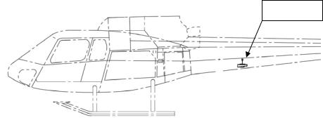
a)GMU 44, Magnetometer
Magnetometer is located in the tail boom between TB 868 and 1578. (Figure 6-01)
GMU 44
|
|
|
|
|
|
|
|
|
|
|
|
|
|
|
TB |
||
TB |
|||||
|
1578 |
||||
868 |
|
||||
|
REF |
||||
REF |
|
||||
|
|
|
|||
|
|
|
|
|
|
Figure 6-01
Access Removal and Installation Methods
i.Removal
1.Un-latch and open the baggage compartment door on the left side of the aircraft.
2.Remove the tail boom closeout panel by loosening the ¼ turn fasteners that hold it in place.
3.If an air conditioner is installed it may be necessary to remove the air conditioner unit to gain access to the magnetometer. Consult the manufacturers Installation and removal instructions for proper removal of unit.
ii.Installation
1.Re-install air conditioner if removed to gain access to the magnetometer. Consult the manufacturers Installation and Removal instructions for proper installation of unit.
2.Re-install tail boom closeout panel by tightening the ¼ turn fasteners that hold it in place.
3.Close the baggage compartment door and latch it.
Caution: Use of power tools during removal or installation of panels and attaching hardware may damage nut plates or deform holes in composite doors, covers, panels, and fairings.
06-00-00
Instructions for Continued Airworthiness |
190-00792-12 Rev 1 |
for the Garmin G500H Installation in Eurocopter AS350 |
Page 19 of 80 |
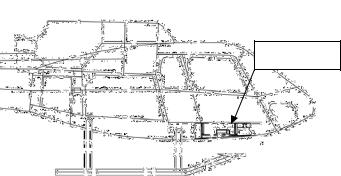
b)GDC 74H, Air Data Computer
GDC 74H is located underneath the cabin floor between station 1790 and 2325 on the left or right side of the aircraft depending on aircraft configuration. (Figure 6-02)
GDC 74H
|
|
|
|
|
|
|
|
|
STA |
STA |
|
|
||
|
|
1790 |
||
2325 |
|
|
||
|
|
REF |
||
REF |
|
|
||
|
|
|
||
|
|
|
|
|
Figure 6-02
Access Removal and Installation Methods
i.Removal
1.Un-latch the Center lower belly access panel.
2.Disconnect the retaining straps that prevent the panel from falling to the floor.
3.If aftermarket items are attached to the Center lower belly panel it may be necessary to remove or disconnect them in order to remove the lower belly panel. Consult the manufacturers Installation and Removal instructions for proper removal of items.
ii.Installation
1.Re-install aftermarket items if removed to gain access to the air data computer. Consult the manufacturers Installation and Removal instructions for proper installation of items.
2.Connect the retaining strap that was disconnected to gain access to the air data computer.
3.Close the Center lower belly access panel and latch it.
Caution: Use of power tools during removal or installation of panels and attaching hardware may damage nut plates or deform holes in composite doors, covers, panels, and fairings.
06-00-00
Instructions for Continued Airworthiness |
190-00792-12 Rev 1 |
for the Garmin G500H Installation in Eurocopter AS350 |
Page 20 of 80 |
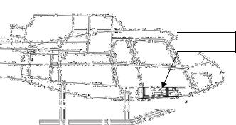
c)GRS 77H, AHRS
GRS 77H is located underneath the cabin floor between station 1790 and 2325 on the left or right side of the aircraft depending on aircraft configuration. (Figure 6-03)
GRS 77H
|
|
|
|
|
|
|
|
|
STA |
STA |
|
|
||
|
|
1790 |
||
2325 |
|
|
||
|
|
REF |
||
REF |
|
|
||
|
|
|
||
|
|
|
|
|
Figure 6-03
Access Removal and Installation Methods
i.Removal
1.Un-screw the Center lower belly access panel.
2.Disconnect the retaining straps that prevent the panel from falling to the floor.
3.If aftermarket items are attached to the Center lower belly panel it may be necessary to remove or disconnect them in order to remove the lower belly panel. Consult the manufacturers Installation and Removal instructions for proper removal of items.
ii.Installation
1.Re-install aftermarket items if removed to gain access to the air data computer. Consult the manufacturers Installation and Removal instructions for proper installation of items.
2.Connect the retaining strap that was disconnected to gain access to the air data computer.
3.Close the Center lower belly access panel and attach screws.
Caution: Use of power tools during removal or installation of panels and attaching hardware may damage nut plates or deform holes in composite doors, covers, panels, and fairings.
06-00-00
Instructions for Continued Airworthiness |
190-00792-12 Rev 1 |
for the Garmin G500H Installation in Eurocopter AS350 |
Page 21 of 80 |
d)Shelf Installation
The shelf installation is located underneath the cabin floor between station 1790 and 2325 on the left or right side of the aircraft depending on aircraft configuration. (Figure 6-04)
Shelf
|
|
|
|
|
|
|
|
|
STA |
STA |
|
|
||
|
|
1790 |
||
2325 |
|
|
||
|
|
REF |
||
REF |
|
|
||
|
|
|
||
|
|
|
||
Figure 6-04
Access Removal and Installation Methods
i.Removal
1.Un-screw the Center lower belly access panel.
2.Disconnect the retaining straps that prevent the panel from falling to the floor.
3.If aftermarket items are attached to the Center lower belly panel it may be necessary to remove or disconnect them in order to remove the lower belly panel. Consult the manufacturers Installation and Removal instructions for proper removal of items.
ii.Installation
1.Re-install aftermarket items if removed to gain access to the air data computer. Consult the manufacturers Installation and Removal instructions for proper installation of items.
2.Connect the retaining strap that was disconnected to gain access to the air data computer.
3.Close the Center lower belly access panel and attach screws.
Caution: Use of power tools during removal or installation of panels and attaching hardware may damage nut plates or deform holes in composite doors, covers, panels, and fairings.
06-00-00
Instructions for Continued Airworthiness |
190-00792-12 Rev 1 |
for the Garmin G500H Installation in Eurocopter AS350 |
Page 22 of 80 |
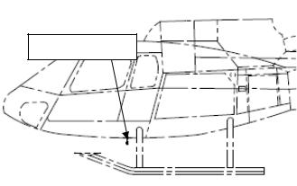
e)Terminal Block Installation
Terminal Block is located underneath the cabin floor between station 1120 and 1502 on the left side of the aircraft. (Figure 6-05)
Terminal Block
|
|
|
|
|
|
|
STA |
STA |
|
|
|
|
|
1502 |
|
1120 |
|
|
|
|
|
REF |
|
REF |
|
|
|
|
|
|
|
|
|
|
|
Figure 6-05
Access Removal and Installation Methods
i.Removal
1.Un-latch the Center lower belly access panel.
2.Disconnect the retaining straps that prevent the panel from falling to the floor.
3.If aftermarket items are attached to the Center lower belly panel it may be necessary to remove or disconnect them in order to remove the lower belly panel. Consult the manufacturers Installation and Removal instructions for proper removal of items.
ii.Installation
1.Re-install aftermarket items if removed to gain access to the air data computer. Consult the manufacturers Installation and Removal instructions for proper installation of items.
2.Connect the retaining strap that was disconnected to gain access to the air data computer.
3.Close the Center lower belly access panel and latch it.
Caution: Use of power tools during removal or installation of panels and attaching hardware may damage nut plates or deform holes in composite doors, covers, panels, and fairings.
06-00-00
Instructions for Continued Airworthiness |
190-00792-12 Rev 1 |
for the Garmin G500H Installation in Eurocopter AS350 |
Page 23 of 80 |
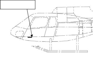
f)GTP 59 OAT Probe Installation
The GTP 59 OAT Probe is located on the existing belly panel between station 2437 and 2351. (Figure 6-06)
GTP 59
|
|
|
|
|
|
|
|
STA |
|
STA |
|
|
||
|
|
2437 |
|
|
2351 |
|
|
|
|
|
|
REF |
|
|
REF |
|
|
|
|
|
|
|
|
|
|
|
|
Figure 6-06 |
|
|
|
|
||
Access Removal and Installation Methods
i.Removal
1.Un-latch the Center lower belly access panel.
2.Disconnect the retaining straps that prevent the panel from falling to the floor.
3.If other aftermarket items are attached to the Center lower belly panel it may be necessary to remove or disconnect them in order to remove the lower belly panel. Consult the manufacturers Installation and Removal instructions for proper removal of items.
ii.Installation
1.Re-install any other aftermarket items if removed to gain access to the air data computer. Consult the manufacturers Installation and Removal instructions for proper installation of items.
2.Connect the retaining strap that was disconnected to gain access to the air data computer.
3.Close the Center lower belly access panel and latch it.
Caution: Use of power tools during removal or installation of panels and attaching hardware may damage nut plates or deform holes in composite doors, covers, panels, and fairings
06-00-00
Instructions for Continued Airworthiness |
190-00792-12 Rev 1 |
for the Garmin G500H Installation in Eurocopter AS350 |
Page 24 of 80 |
Loading...