


Garmin echoMAP 71sv, echoMAP 72sv, echoMAP 73sv, echoMAP 74dv, echoMAP 74sv Installation Instructions
...
echoMAP™ 70/90 Series Installation Instructions
To obtain the best performance and to avoid damage to your boat, install the device according to these instructions.
Read all installation instructions before proceeding with the installation. If you experience difficulty during the installation, contact Garmin® Product Support.
Important Safety Information
 WARNING
See the Important Safety and Product Information guide in the product box for product warnings and other important information.
When connecting the power cable, do not remove the in-line fuse holder. To prevent the possibility of injury or product damage caused by fire or overheating, the appropriate fuse must be in place as indicated in the product specifications. In addition, connecting the power cable without the appropriate fuse in place voids the product warranty.
 CAUTION
Always wear safety goggles, ear protection, and a dust mask when drilling, cutting, or sanding.
NOTICE
When drilling or cutting, always check what is on the opposite side of the surface.
To obtain the best performance and to avoid damage to your boat, install the device according to these instructions.
Read all installation instructions before proceeding with the installation. If you experience difficulty during the installation, contact Garmin Product Support.
Registering Your Device
Help us better support you by completing our online registration today.
•Go to http://my.garmin.com.
•Keep the original sales receipt, or a photocopy, in a safe place.
Contacting Garmin Product Support
•Go to www.garmin.com/support for in-country support information.
•In the USA, call 913-397-8200 or 1-800-800-1020.
•In the UK, call 0808 238 0000.
•In Europe, call +44 (0) 870 850 1241.
Tools Needed
•Drill and drill bits
•#2 Phillips screwdriver
•Jigsaw or rotary tool
•File and sandpaper
•Marine sealant (optional)
Mounting Considerations
The device can be mounted using the included bracket, or it can be mounted flush with the dashboard using a flush-mount kit (may be sold separately).
Before permanently installing any part of your device, you should plan the installation by determining the location of the various components.
•The mounting location must provide a clear view of the screen and access to the keys on the device.
•The mounting location must be sturdy enough to support the device and the mount.
•The cables must be long enough to connect the components to each other and to power.
•The cables can be routed under the bail mount or behind the device.
•To avoid interference with a magnetic compass, the device should not be installed closer to a compass than the compass-safe distance value listed in the product specifications.
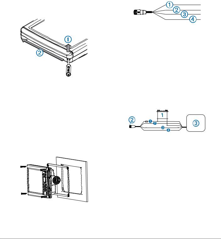
Bail Mounting the Device
NOTICE
If you are mounting the bracket on fiberglass with screws, it is recommended to use a countersink bit to drill a clearance counterbore through only the top gel-coat layer. This will help to avoid any cracking in the gel-coat layer when the screws are tightened.
Stainless-steel screws may bind when screwed into fiberglass and overtightened. Garmin recommends applying an anti-seize lubricant to the screws before installing them.
1Select the mounting hardware appropriate for your mounting surface and for the bail-mount bracket.
2 Using the bail-mount bracket as a template, mark the pilot
À
holes through the screw holes .
Á
3Using a drill bit appropriate for the mounting hardware, drill the four pilot holes.
4Using the selected mounting hardware, secure the bail-mount bracket to the mounting surface.
5 |
Place the device into the cradle Â. |
6 |
Install the bail-mount knobs on the sides of the device. |
|
à |
7Place the cradle in the bail-mount bracket and tighten the bail-mount knobs.
Flush Mounting the Device
NOTICE
Be careful when cutting the hole to flush mount the device. There is only a small amount of clearance between the case and the mounting holes, and cutting the hole too large could compromise the stability of the device after it is mounted.
Using a metal pry tool such as a screwdriver can damage the trim caps and the device. Use a plastic pry tool when possible.
December 2014 |
Printed in Taiwan |
190-01835-02_0B |
A flush-mount template and hardware can be used to mount the device in your dashboard.
1Trim the template and make sure it fits in the location where you want to mount the device.
2 Secure the template to the selected mounting location.
3Using a 9.5 mm (3/8 in.) drill bit, drill one or more of the holes inside the corners of the solid line on the template to prepare the mounting surface for cutting.
4Using a jigsaw or rotary cutting tool, cut the mounting surface along the inside of the solid line indicated on the template.
5 Place the device into the cutout to test the fit.
6If necessary, use a file and sandpaper to refine the size of the hole.
7NOTE: Not all devices have trim caps.
Using a pry tool such as a flat piece of plastic or a screwdriver, carefully pry up the corners of the trim caps
À
and slide the pry tool to the center to remove the trim caps.
Á
18Secure the device to the mounting surface using the included screws.
19Install the trim caps by snapping them in place around the edges of the device.
Wiring Harness
•The wiring harness connects the device to power and NMEA® 0183 devices.
•The device has one internal NMEA 0183 port that is used to connect to NMEA 0183 compliant devices.
•If it is necessary to extend the power and ground wires, you must use .82 mm2 (18 AWG) or larger wire.
•If it is necessary to extend the NMEA 0183 or alarm wires, you must use 22 AWG (.33 mm2) wire.
8Ensure the mounting holes on the device line up with the pilot holes on the template.
9If the mounting holes on the device do not line up, mark the new pilot-hole locations.
10Using a 3.2 mm (1/8 in.) drill bit, drill the pilot holes. 11Remove the template from the mounting surface.
12If you will not have access to the back of the device after you mount it, connect all necessary cables to the device before placing it into the cutout.
NOTE: To prevent corrosion of the metal contacts, cover unused connectors with weather caps.
13Install the rubber gasket pieces on the back of the device.
The pieces of the rubber gasket have adhesive on the back. Make sure you remove the protective liner before installing them on the device.
14Place the device into the cradle.
15Securely connect each cable to a port on the cradle. 16Place the locking bracket over the cables.
17Place the device into the cutout.
Item |
Wire Function |
Wire Color |
À |
NMEA 0183 internal port Rx (in) |
Brown |
|
|
|
Á |
NMEA 0183 internal port Tx (out) |
Blue |
|
|
|
 |
Ground (power and NMEA 0183) |
Black |
|
|
|
à |
Power |
Red |
Connecting the Wiring Harness to Power
1Route the wiring harness to the power source and to the device.
2Connect the red wire to the positive (+) battery terminal, and connect the black wire to the negative (-) battery terminal.
NMEA 0183 Connection Considerations
•The installation instructions provided with your NMEA 0183 compatible device should contain the information you need to identify the transmitting (Tx) and receiving (Rx) A (+) and B (-) wires.
NMEA 0183 Connection Diagram


 +
+ -
-


Item |
Description |
À |
12 Vdc power source |
Á |
Wiring harness |
|
|
 |
NMEA 0183-compliant device |
|
|
Item |
Garmin Wire |
Garmin Wire |
NMEA 0183 Device Wire |
|
Function |
Color |
Function |
Ê |
Power |
Red |
Power |
Ë |
Ground |
Black |
Data ground |
|
|
|
|
Ì |
Tx |
Blue |
Rx/A (+) |
|
|
|
|
Í |
Rx |
Brown |
Tx/A (+) |
Installing the Cables and Connectors
Wiring to Power
1Route the power cable from the swivel mount to the boat battery or fuse block.
2If necessary, extend the wires using .82 mm2 (18 AWG) or larger wire.
3Connect the red wire to the positive terminal on the battery or fuse block, and connect the black wire to the negative terminal.
2
 Loading...