


AIS 600 Instructions
UsetheseinstructionstoprogramandinstalltheGarmin® AIS600marineAutomaticIdentificationSystem(AIS)ClassBtransponderdevice.
Comparethecontentsofthispackagewiththepackinglistonthebox.Ifanypiecesaremissing,contactyourGarmindealerimmediately.
WARNING
Whennavigating,carefullycompareinformationprovidedbytheunittoallavailablenavigationsources,includinginformationfromvisual sightings,localwaterwayrulesandrestrictions,andmaps.Forsafety,alwaysresolveanydiscrepanciesorquestionsbeforecontinuing navigation.
Usethisunitonlyasanavigationalaid.Donotattempttousetheunitforanypurposerequiringprecisemeasurementofdirection,distance, location,ortopography.
Thisproduct,itspackaging,anditscomponentscontainchemicalsknowntotheStateofCaliforniatocausecancer,birthdefects,or reproductiveharm.ThisNoticeisprovidedinaccordancewithCalifornia’sProposition65.Seewww.garmin.com/prop65formoreinformation.
Caution
Wearsafetygogglesandadustmaskwhendrilling,cutting,orsanding.
Notice
Topreventpossibledamagetoyourequipment,theVHFantennamustbeconnectedtotheAIS600beforetransmitting.Thisensuresthatthe poweroutputtotheantennaportdissipatesproperlywhentransmitting.
Electromagnetic Energy Exposure and Antenna Mounting
TheAIS600generatesandradiatesradiofrequency(RF)electromagneticenergy(EME).Failuretoobservetheseguidelinesmayexpose personstoRFradiationabsorptionexceedingthemaximumpermissibleexposure(MPE).
GarmindeclaresanMPEradiusof59in.(1.5m.)forthissystem,whichwasdeterminedusing2wattsoutputtoanomni-directional9dBigain antenna.Theantennashouldbeinstalledsuchthatadistanceof59in.(1.5m)ismaintainedbetweentheantennaandallpersons.
WhensharingtheVHFantennawithaVHFradio,refertothedocumentationprovidedwiththeradioforadditionalMPEinformationspecific totheinstalledVHFradio.
WARNING:
Radiooperatorswithcardiacpacemakers,life-supportmachines,orelectricalmedicalequipmentshouldnotbeexposedtoexcessiveradio- frequencyfields.
Operatethedeviceinaccordancewiththeinstructionssupplied.
notice
Thedevicecomplieswithinternationallyrecognizedstandardscoveringhumanexposuretoelectromagneticfieldsfromradiodevices.
Checkwiththelocalauthoritiesforanyantennaoroperationalrestrictionsthatmayapply.
Safe Compass Distance
EnsurethatyouinstalltheAIS600transceiverboxatleast153/4 in.(40 cm)fromanycompass.Testyourcompasstoverifythatitoperates correctlywhenthedeviceisoperating.
Licensing Requirements
Inmanycountries,theoperationofanAISdeviceisincludedintheVHFlicenseprovisions.Therefore,thevesselonwhichtheAIS600is installedmustpossessacurrentVHFlicensethatliststheAISsystem,thevesselcallsign,andthevesselMaritimeMobileServiceIdentity (MMSI)number.ContacttherelevantauthorityinyourcountrytoensurethatyourVHFlicensecoverstheAIS600device.
May 2012 |
190-01151-00 Rev. E |
Printed in Germany |

Programming the AIS 600
BeforetheAIS600canbeusedonaboat,itmustbeprogrammed withauniqueMMSInumberandwithadditionalvessel-specific staticdata.TheMMSInumbermustbeprogrammedbyan authorizedmarine-electronicsdealerorinstaller.UsetheAIS600 SetupSoftwareontheincludedCD-ROMtoprogramtheAIS600.
Notice
In the USA, it is prohibited under FCC regulations to enter incorrect or improper data, and it is prohibited for any person other than the manufacturer or the installing dealer to input MMSI data.
ItisaviolationoftherulesoftheFederalCommunications CommissiontoinputanMMSIthathasnotbeenproperlyassigned totheuser,ortootherwiseinputanyinaccuratedatainthisdevice.
Preparing the AIS 600 and the PC for Programming
PC Requirements
Microsoft® Windows® 2000ornewer;minimum32MBofRAM; minimum10MBoffreehard-drivespace.
Installing the AIS 600 Setup Software:
1.Insert the CD-ROM provided with theAIS 600 into your computer. The Installation Wizard for theAIS 600 Setup Software runs automatically.
NOTE: To run theAIS 600 programming Setup Software installer manually, run the Setup.exe file on the CD-ROM.
2.Follow the on-screen instructions to install the AIS 600 Setup Software on your computer.
Connecting the AIS 600 to a PC for programming:
1.Connect the AIS 600 transceiver box to a 12 or 24 Vdc power source using the power/data cable (see page 5).
NOTE: To ensure that the AIS 600 device powers on for programming, connect the red wire from the power/data cable to the positive (+) terminal of the 12 or 24 Vdc power source, and connect both the black wire and the yellow wire from the power/ data cable to the negative (-) terminal of the 12 or 24 Vdc power source.
2.Use the included mini USB cable to connect the USB port on the AIS 600 transceiver box to a USB port on your computer. The Windows Found New Hardware Wizard runs automatically.
3.Follow the on-screen instructions to complete the Found New Hardware Wizard.
NOTE: If the Found New Hardware Wizard does not successfully install the driver, open the Driver folder on the CD-ROM and run CDM20600.exe to install the AIS 600 driver on your computer.
Assigning Data to the AIS 600
TheAIS600mustbeprogrammedwithavalidvesselMMSI numberbeforeuse.UntilavalidMMSInumberisprogrammed,the AIS600willoperateinsilentmodeonly.Wheninsilentmode,the AIS600willnottransmitpositiondata,althoughitcanstillreceive AISsignals.Optionally,theAIS600transmitsthefollowingstatic vesseldatawhenassigned:
•Vesselname
•Vesselcallsign
•Vesseltype
•Vesseldimensions(includingthelocationoftheGPSantennaon theboat)
To begin communication with the AIS 600:
1.Ensure that theAIS 600 transceiver box is connected to a 12 or 24 Vdc power source using the power/data cable, and that the AIS 600 is connected to the PC using the included mini USB cable.
2.Launch the AIS 600 Setup Software.An icon was placed on the desktop when you installed the software.
3.Click Connect in the Connection and Status window.
To assign an MMSI number to the AIS 600:
Note:After you save the assigned MMSI number to theAIS 600, the MMSI number cannot be changed.
1.On the Static Data tab of theAIS 600 Setup Software, enter a nine-digit MMSI number in the MMSI field.
2.Click Save data to AIS600.
To program static vessel data on the AIS 600:
Note: Vessel static data, unlike an MMSI number, can be reprogrammed if necessary.
1.On the Static Data tab of theAIS 600 Setup Software, enter the vessel name, the vessel call sign, the type of vessel, and the location of the GPS antenna on the vessel.
2.Click Save data to AIS600.
To complete the programming process:
1.From the File menu of the AIS 600 Setup Software, select Exit.
2.Disconnect the AIS 600 transceiver box from the computer.
2 |
AIS 600 Instructions |

AIS 600 Wiring Layout: AIS 600 Connected to a Chartplotter through a NMEA 2000 Network
GPS 17x GPS antenna*
(not included)
GA 30 GPS antenna* (included)
RF cable to VHF antenna |
RF interconnect cable |
|
(not included) |
||
(included) |
||
|
|
|
|
VHF radio** |
|
|
|
|
(optional - not |
|
|
AIS 600 |
|
included) |
|
|
|
|
||
|
|
page 7 |
|
|
|
|
network— |
Chartplotter |
|
|
|
(optional - not |
||
|
|
included) |
||
|
|
2000 |
||
|
|
|
||
|
|
NMEA |
Chartplotter power |
|
|
|
NMEA 2000 network power |
||
|
- included |
|
||
|
|
(not included) |
||
|
|
powerradio |
||
|
cable |
NMEA 2000 drop cable |
VHF |
|
-mode switch |
(included) |
|||
SRM |
|
|||
|
|
|||
(optional - not included) |
|
|
||
|
|
|
||
SRM message switch |
|
AIS 600 power/data cable |
(included) |
|
|
|
|
||
(optional - not included) |
|
|
|
|
for silentpageSee8 |
|
|
12 or 24 Vdc |
|
mode and SRM |
|
|
||
|
|
|
||
message wiring |
|
|
|
|
assignments |
|
|
|
|
Notes: |
|
|
|
|
* The AIS 600 must be connected to the included GA 30 GPS antenna. The AIS 600 does not share GPS information with any other devices on the boat. If you have a chartplotter |
||||
on your boat, it must receive GPS information from a separate antenna, such as a GPS 17x. |
||||
** The AIS 600 does not need to be installed alongside a VHF radio, but they can share the same VHF antenna if they are both installed on your boat. |
||||
Silent |
|
|
|
|
3
AIS 600 Instructions
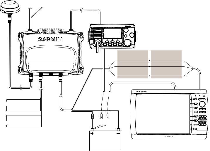
AIS 600 Wiring Layout: AIS 600 Connected to a Garmin Chartplotter through NMEA 0183
GA 30 GPS antenna* |
|
|
(included) |
|
|
RF cable to VHF antenna |
RF interconnect cable |
|
(not included) |
||
(included) |
||
|
VHF radio** (optional - not included)
AIS 600 transceiver box
 Silent-mode switch
  (optional - not included)
SRM switch  (optional - not included)
See page 8 for silent mode and Safety-Related Message (SRM) wiring assignments
Notes:
|
Wire color [function] |
Wire color [function]*** |
|
|
> Gray [Tx A (+)] |
White [Rx A (+)] |
> |
|
> Pink [Tx B (-)] |
Orange/White [Rx B (-)]> |
|
|
Yellow |
Orange |
|
radio VHF |
[power toggle] |
[power toggle] |
|
Chartplotter power |
|
|
|
power |
|
|
|
|
|
Garmin NMEA 0183- |
|
|
|
compatible chartplotter |
|
|
|
(optional - not included) |
|
12 or 24 Vdc
*TheAIS 600 must be connected to the included GA 30 GPS antenna. The AIS 600 does not share GPS information with any other devices on the boat. If you have a chartplotter on your boat, it must receive GPS information from a separate antenna, such as a GPS 17x.
**TheAIS 600 does not need to be installed alongside a VHF radio, but they can share the same VHF antenna if they are both installed on your boat.
***The listed wire colors are for the NMEA 0183 Port 1 input on a Garmin GPSMAP 4000/5000/6000/7000 series chartplotter. Refer to the installation instructions provided with your Garmin chartplotter if you want to wire the AIS 600 to a different model of Garmin chartplotter or to a different NMEA0183 port on a GPSMAP 4000/5000/6000/7000 series chartplotter.
If you are connecting theAIS 600 to a non-garmin chartplotter, see page 8 for detailed wiring assignments.
4 |
AIS 600 Instructions |
 Loading...