


G1000 System
Maintenance Manual
Diamond DA 40
190-00303-03 |
January 2007 |
Revision 6 |

© Copyright 2007
Garmin Ltd. or its subsidiaries All Rights Reserved
Except as expressly provided herein, no part of this manual may be reproduced, copied, transmitted, disseminated, downloaded or stored in any storage medium, for any purpose without the express prior written consent of Garmin. Garmin hereby grants permission to download a single copy of this manual and of any revision to this manual onto a hard drive or other electronic storage medium to be viewed and to print one copy of this manual or of any revision hereto, provided that such electronic or printed copy of this manual or revision must contain the complete text of this copyright notice and provided further that any unauthorized commercial distribution of this manual or any revision hereto is strictly prohibited.
Garmin International, Inc.
1200 E. 151st Street
Olathe, KS 66062 USA
Telephone: 913-397-8200
www.garmin.com
Garmin (Europe) Ltd.
Unit 5, The Quadrangle
Abbey Park Industrial Estate
Romsey, SO51 9DL U.K.
Telephone: 44/1794.519944
RECORD OF REVISIONS
Revision |
Revision Date |
Description |
ECO # |
1 |
06/04/04 |
Experimental Release |
------ |
2 |
6/17/04 |
Update for STC |
26291 |
3 |
6/21/04 |
Update AW Limitations, Add Document Pagination |
26344 |
|
|
Table. |
|
4 |
8/24/04 |
Update for new GTX 33 SW |
27110 |
5 |
9/3/04 |
Update for optional KAP 140 AFCS |
27244 |
6 |
1/25/07 |
Update GDC Testing Process |
42752 |
DOCUMENT PAGINATION
Section |
Pagination |
|
Table of Contents |
i – vi |
|
Section 1 |
1-1 |
– 1-4 |
Section 2 |
2-1 – 2-26 |
|
Section 3 |
3-1 – 3-12 |
|
Section 4 |
4-1 |
– 4-12 |
Section 5 |
5-1 |
– 5-24 |
Section 6 |
6-1 |
– 6-8 |
Section 7 |
7-1 |
– 7-34 |
Section 8 |
8-1 |
– 8-4 |
Appendix A |
A-1 |
– A-6 |
Appendix B |
B-1 |
– B-16 |
Page A |
G1000/DA40 System Maintenance Manual |
Revision 6 |
190-00303-03 |

INFORMATION SUBJECT TO EXPORT CONTROL LAWS
This document may contain information which is subject to the Export Administration Regulations ("EAR") issued by the United States Department of Commerce (15 CFR, Chapter VII, Subchapter C) and which may not be exported, released, or disclosed to foreign nationals inside or outside of the United States without first obtaining an export license. A violation of the EAR may be subject to a penalty of up to 10 years imprisonment and a fine of up to $1,000,000 under Section 2410 of the Export Administration Act of 1979. Include this notice with any reproduced portion of this document.
WARNING
This product, its packaging, and its components contain chemicals known to the State of California to cause cancer, birth defects, or reproductive harm. This Notice is being provided in accordance with California's Proposition 65. If you have any questions or would like additional information, please refer to our web site at www.garmin.com/prop65.
CAUTION
The GDU 1040s use a lens coated with a special anti-reflective coating that is very sensitive to skin oils, waxes and abrasive cleaners. CLEANERS CONTAINING AMMONIA WILL HARM THE ANTIREFLECTIVE COATING. It is very important to clean the lens using a clean, lint-free cloth and an eyeglass lens cleaner that is specified as safe for anti-reflective coatings.
CAUTION
All G1000 screen shots used in this document are current at the time of publication. Screen shots are intended to provide visual reference only. All information depicted in screen shots, including software file names, versions and part numbers, is subject to change and may not be up to date.
G1000/DA40 System Maintenance Manual |
Page i |
190-00303-03 |
Revision 6 |

This page intentionally left blank.
Page ii |
G1000/DA40 System Maintenance Manual |
Revision 6 |
190-00303-03 |

|
TABLE OF CONTENTS |
|
PARAGRAPH |
PAGE |
|
1 |
INTRODUCTION |
|
1.1 |
CONTENT, SCOPE, PURPOSE ........................................................................................................... |
1-1 |
1.2 |
ORGANIZATION .............................................................................................................................. |
1-1 |
1.3 |
DEFINITIONS/ABBREVIATIONS....................................................................................................... |
1-2 |
1.4 |
REFERENCE PUBLICATIONS............................................................................................................ |
1-3 |
1.5 |
DISTRIBUTION ................................................................................................................................ |
1-3 |
2 |
SYSTEM DESCRIPTION |
|
2.1 |
EQUIPMENT DESCRIPTIONS............................................................................................................ |
2-1 |
2.2 |
EQUIPMENT LOCATIONS ................................................................................................................ |
2-8 |
2.3 |
REMOTE AVIONICS ENCLOSURE .................................................................................................... |
2-9 |
2.4 |
ELECTRICAL POWER DISTRIBUTION ............................................................................................ |
2-11 |
2.5 |
LIGHTNING STRIKE PROTECTION ................................................................................................. |
2-12 |
2.6 |
SPIDER GROUNDS....................................................................................................................... |
2-16 |
2.7 |
SENSOR INSTALLATIONS .............................................................................................................. |
2-17 |
2.8 |
G1000 SYSTEM COMMUNICATIONS ............................................................................................. |
2-23 |
3 G1000 CONTROL & OPERATION |
|
|
3.1 |
USER INTERFACE............................................................................................................................ |
3-2 |
3.2 |
G1000 NORMAL MODE .................................................................................................................. |
3-3 |
3.3 |
REVERSIONARY MODE................................................................................................................... |
3-4 |
3.4 |
CONFIGURATION MODE OVERVIEW .............................................................................................. |
3-5 |
3.5 |
CONFIGURATION MODE NAVIGATION ......................................................................................... |
3-11 |
4 |
G1000 CONTINUED AIRWORTHINESS |
|
4.1 |
AIRWORTHINESS LIMITATIONS ...................................................................................................... |
4-1 |
4.2 |
SERVICING INFORMATION.............................................................................................................. |
4-1 |
4.3 |
ON CONDITION SERVICING ............................................................................................................ |
4-1 |
4.4 |
MAINTENANCE REQUIREMENTS .................................................................................................... |
4-3 |
4.5 |
1000 HOUR INSPECTION................................................................................................................. |
4-5 |
4.6 |
ELECTRICAL BONDING TEST.......................................................................................................... |
4-7 |
4.7 |
FUEL TANK PROBE RE-CALIBRATION............................................................................................ |
4-8 |
4.8 |
GRS 77 EARTH MAGNETIC FIELD UPDATES................................................................................ |
4-11 |
5 |
TROUBLESHOOTING |
|
5.1 |
G1000 ALERTING SYSTEM ............................................................................................................. |
5-2 |
5.2 |
SYSTEM ANNUNCIATIONS.............................................................................................................. |
5-4 |
5.3 |
DA 40-SPECIFIC ALERTS................................................................................................................ |
5-8 |
5.4 |
GDU 1040 TROUBLESHOOTING ..................................................................................................... |
5-9 |
5.5 |
GDU 1040 ALERTS ........................................................................................................................ |
5-9 |
5.6 |
GMA ALERTS............................................................................................................................... |
5-12 |
5.7 |
GIA 63 TROUBLESHOOTING......................................................................................................... |
5-13 |
5.8 |
GIA ALERT MESSAGES ................................................................................................................ |
5-14 |
5.9 |
GEA TROUBLESHOOTING ............................................................................................................ |
5-19 |
5.10 |
GTX TROUBLESHOOTING ........................................................................................................... |
5-20 |
5.11 |
GRS 77/GMU 44 TROUBLESHOOTING........................................................................................ |
5-21 |
5.12 |
GDC 74A TROUBLESHOOTING ................................................................................................... |
5-23 |
6 G1000 EQUIPMENT REMOVAL & REPLACEMENT |
|
|
6.1 |
GDU 1040 MFD & PFD................................................................................................................. |
6-2 |
6.2 |
GMA 1347 AUDIO PANEL.............................................................................................................. |
6-2 |
6.3 |
GIA 63 INTEGRATED AVIONICS UNITS .......................................................................................... |
6-3 |
|
|
|
G1000/DA40 System Maintenance Manual |
Page iii |
|
190-00303-03 |
Revision 6 |
|

6.4 |
GEA 71 ENGINE/AIRFRAME UNIT ................................................................................................. |
6-3 |
6.5 |
GTX 33 TRANSPONDER ................................................................................................................. |
6-4 |
6.6 |
GDC 74A AIR DATA COMPUTER ................................................................................................... |
6-4 |
6.7 |
GTP 59 OAT PROBE ...................................................................................................................... |
6-4 |
6.8 |
GRS 77 AHRS ............................................................................................................................... |
6-5 |
6.9 |
GMU 44 MAGNETOMETER............................................................................................................. |
6-5 |
6.10 CONFIGURATION MODULE REMOVAL & REPLACEMENT ............................................................. |
6-6 |
|
6.11 GEA 71 BACKSHELL THERMOCOUPLE REMOVAL & REPLACEMENT........................................... |
6-7 |
|
7 G1000 EQUIPMENT CONFIGURATION & TESTING |
|
|
7.1 |
GDU 1040 MFD & PFD................................................................................................................. |
7-1 |
7.2 |
GMA 1347 AUDIO PANEL.............................................................................................................. |
7-5 |
7.3 |
GIA 63 INTEGRATED AVIONICS UNIT............................................................................................ |
7-8 |
7.4 |
GEA 71 ENGINE/AIRFRAME UNIT ............................................................................................... |
7-14 |
7.5 |
GTX 33 TRANSPONDER ............................................................................................................... |
7-17 |
7.6 |
GDC 74A AIR DATA COMPUTER ................................................................................................. |
7-21 |
7.7 |
GRS 77 AHRS / GMU 44 MAGNETOMETER................................................................................ |
7-25 |
7.8 |
SOFTWARE/CONFIGURATION TROUBLESHOOTING ...................................................................... |
7-34 |
8 SYSTEM RETURN TO SERVICE PROCEDURE |
|
|
8.1 |
GPS FAILURE TEST ........................................................................................................................ |
8-1 |
8.2 |
GIA FAILURE TEST ........................................................................................................................ |
8-2 |
8.3 |
DISPLAY FAILURE TEST ................................................................................................................. |
8-2 |
8.4 |
AHRS/ADC BACKUP PATH TEST .................................................................................................. |
8-3 |
8.5 |
FLIGHT TEST .................................................................................................................................. |
8-4 |
8.6 |
MAINTENANCE RECORDS............................................................................................................... |
8-4 |
APPENDIX A INSTALLATION DATA |
|
|
A.1 G1000 EQUIPMENT LIST .............................................................................................................. |
A-1 |
|
A.2 ADDITIONAL EQUIPMENT REQUIRED........................................................................................... |
A-2 |
|
A.3 |
OPTIONAL EQUIPMENT ................................................................................................................ |
A-2 |
A.4 |
PARTS LIST................................................................................................................................... |
A-3 |
A.5 WEIGHT & BALANCE ................................................................................................................... |
A-5 |
|
APPENDIX B G1000 SOFTWARE/CONFIGURATION PROCEDURE |
|
|
B.1 SYSTEM POWER UP ...................................................................................................................... |
B-2 |
|
B.2 MFD & PFD SOFTWARE LOAD.................................................................................................... |
B-3 |
|
B.3 |
INITIAL G1000 CONFIGURATION ................................................................................................. |
B-4 |
B.4 GIA SOFTWARE LOAD ................................................................................................................. |
B-5 |
|
B.5 |
GIA CONFIGURATION .................................................................................................................. |
B-7 |
B.6 FINAL LRU SOFTWARE LOAD ..................................................................................................... |
B-8 |
|
B.7 FINAL LRU CONFIGURATION .................................................................................................... |
B-14 |
|
B.8 SOFTWARE LOAD CONFIRMATION............................................................................................. |
B-15 |
|
B.9 AVIATION DATABASE LOADING ................................................................................................ |
B-16 |
|
B.10 FINAL SYSTEM TESTING ............................................................................................................ |
B-16 |
|
Page iv |
G1000/DA40 System Maintenance Manual |
Revision 6 |
190-00303-03 |

LIST OF ILLUSTRATIONS
FIGURE |
|
PAGE |
Figure 2-1. |
G1000 / DA 40 Panel Installation .......................................................................................... |
2-2 |
Figure 2-2. DA40 Panel (Rear View) ....................................................................................................... |
2-4 |
|
Figure 2-3. GTP 59 OAT Probe................................................................................................................ |
2-5 |
|
Figure 2-4. GRS 77 Mount ....................................................................................................................... |
2-6 |
|
Figure 2-5. |
GMU 44 Installation............................................................................................................... |
2-7 |
Figure 2-6. G1000 in DA 40 Equipment Locations.................................................................................. |
2-8 |
|
Figure 2-7. Remote Avionics Enclosure ................................................................................................... |
2-9 |
|
Figure 2-8. |
G1000/DA40 Electrical Distribution.................................................................................... |
2-11 |
Figure 2-9. |
TVS & Fuse Installation....................................................................................................... |
2-12 |
Figure 2-10. |
Lightning Protection Components ..................................................................................... |
2-13 |
Figure 2-11. Component Plate Dimensions ............................................................................................ |
2-13 |
|
Figure 2-12. Component Wiring Diagram.............................................................................................. |
2-14 |
|
Figure 2-13. |
SPIDER Ground Installation.............................................................................................. |
2-16 |
Figure 2-14. MAP Sensor ....................................................................................................................... |
2-17 |
|
Figure 2-15. |
Oil Pressure Sensor ............................................................................................................ |
2-17 |
Figure 2-16. |
Oil Temperature Sensor ..................................................................................................... |
2-18 |
Figure 2-17. |
Fuel Pressure Sensor .......................................................................................................... |
2-18 |
Figure 2-18. |
Tachometer Sensor............................................................................................................. |
2-19 |
Figure 2-19. Fuel Flow Sensor & Fire Sleeve ........................................................................................ |
2-19 |
|
Figure 2-20. Fuel Flow Assembled......................................................................................................... |
2-20 |
|
Figure 2-21. |
Fuel Flow Bracket .............................................................................................................. |
2-20 |
Figure 2-22. CHT Probe ......................................................................................................................... |
2-21 |
|
Figure 2-23. EGT Probe.......................................................................................................................... |
2-21 |
|
Figure 2-24. |
Alternator Current Sensor Installation ............................................................................... |
2-22 |
Figure 2-25. |
Flight Instrumentation Interface......................................................................................... |
2-23 |
Figure 2-26. |
G1000 Engine/Airframe Interface...................................................................................... |
2-24 |
Figure 2-27. G1000 Navigation/Communications.................................................................................. |
2-25 |
|
Figure 3-1. GDU 1040 Control Interface.................................................................................................. |
3-1 |
|
Figure 3-2. GMA 1347 Controls............................................................................................................... |
3-1 |
|
Figure 3-3. G1000 Softkeys...................................................................................................................... |
3-2 |
|
Figure 3-4. Normal Mode ......................................................................................................................... |
3-3 |
|
Figure 3-5. MFD Failure Mode................................................................................................................. |
3-4 |
|
Figure 3-6. PFD Failure Mode.................................................................................................................. |
3-4 |
|
Figure 3-7. G1000 LRU Configuration File Storage ................................................................................ |
3-7 |
|
Figure 3-8. GRS/GDC Configuration Settings Storage ............................................................................ |
3-8 |
|
Figure 3-9. SET>ACTV Diagram............................................................................................................. |
3-9 |
|
Figure 3-10. Loss of Communication ..................................................................................................... |
3-10 |
|
Figure 3-11. |
Configuration Status........................................................................................................... |
3-10 |
Figure 3-12. |
Data Transmission Indicators............................................................................................. |
3-10 |
Figure 3-13. |
Configuration Page Navigator............................................................................................ |
3-11 |
Figure 5-1. System Status Page (AUX Group Normal Mode).................................................................. |
5-1 |
|
Figure 5-2. |
Alerts & Annunciations.......................................................................................................... |
5-2 |
Figure 5-3. WARNING Softkey Annunciation ........................................................................................ |
5-3 |
|
Figure 5-4. CAUTION Softkey Annunciation.......................................................................................... |
5-3 |
|
Figure 5-5. ADVISORY Softkey Annunciation ....................................................................................... |
5-3 |
|
Figure 5-6. |
System Annunciations............................................................................................................ |
5-4 |
Figure 5-7. GMA 1347 Data Paths ......................................................................................................... |
5-12 |
|
Figure 5-8. GEA 71 Data Paths .............................................................................................................. |
5-19 |
|
Figure 5-9. GTX 33 Data Paths .............................................................................................................. |
5-20 |
|
Figure 5-10. GRS 77 Data Paths............................................................................................................. |
5-22 |
|
|
|
|
G1000/DA40 System Maintenance Manual |
Page v |
|
190-00303-03 |
Revision 6 |
|

Figure 5-11. GDC 74A Data Paths ......................................................................................................... |
5-23 |
||
Figure 6-1. |
|
System Status Page (Configuration Mode) ............................................................................ |
6-1 |
Figure 6-2. |
Configuration Module Installation ......................................................................................... |
6-6 |
|
Figure 6-3. |
GEA Backshell Thermocouple............................................................................................... |
6-7 |
|
Figure 7-1. |
G1000 Normal Mode Check .................................................................................................. |
7-4 |
|
Figure 7-2. |
G1000 Reversionary Mode Check ......................................................................................... |
7-4 |
|
Figure 7-3. |
Marker Beacon Symbology.................................................................................................... |
7-7 |
|
Figure 7-4. |
|
GPS Signal Status................................................................................................................. |
7-11 |
Figure 7-5. |
G1000 Engine/Airframe Indicators...................................................................................... |
7-16 |
|
|
|
LIST OF TABLES |
|
TABLE |
|
|
PAGE |
Table 1-1. Required Documents ............................................................................................................... |
1-3 |
||
Table 1-2. Reference Documents.............................................................................................................. |
1-3 |
||
Table 4-1. |
Required Maintenance............................................................................................................. |
4-3 |
|
Table 4-2. |
1000 Hour Inspection Procedure ............................................................................................. |
4-5 |
|
Table 6-1. |
Thermocouple Kit (011-00981-00) ......................................................................................... |
6-7 |
|
Page vi |
G1000/DA40 System Maintenance Manual |
Revision 6 |
190-00303-03 |

1 INTRODUCTION
1.1Content, Scope, Purpose
This document provides Instructions for Continued Airworthiness (ICA) for the Garmin G1000 Integrated Cockpit avionics suite as installed in the Diamond Model DA 40 in accordance with the STC issued under FAA STC SA01254WI. This document satisfies the requirements for continued airworthiness as defined by 14 CFR Part 23.1529 and Appendix G. Information in this document is required to maintain the continued airworthiness of the G1000 integrated cockpit system, as installed in the Diamond DA 40.
1.1.1Applicability
This document applies to all Diamond Aircraft Industries, Inc., Model DA 40 aircraft equipped with the G1000 cockpit installed in accordance with the STC issued under FAA STC SA01254 “original issue” configuration. G1000 System Maintenance Manual – Diamond DA40 190-00545-00 applies to later configurations.
1.2Organization
The following outline briefly describes the organization of this manual:
Section 2: System Description
Provides a complete description of the type design change associated with installing the G1000 integrated cockpit system in the Diamond DA 40. An overview of the G1000 system interface is also provided.
Section 3: G1000 Control & Operation
Presents basic control and operation information specifically tailored to maintenance practices. Basic G1000 Configuration Mode operation is also described.
Section 4: G1000 Continued Airworthiness
Provides maintenance instructions for continued airworthiness of the G1000 system.
Section 5: Troubleshooting
Provides troubleshooting information to aid in diagnosing and resolving potential problems with the G1000 system.
Section 6: G1000 Equipment Removal & Replacement
Gives instructions for the removal and replacement of G1000 equipment.
Section 7: G1000 Equipment Configuration & Testing
Gives instructions for loading software, configuring, and testing of G1000 equipment.
Section 8: System Return to Service Procedure
Specifies return-to-service procedures to be performed upon completion of maintenance of the G1000 system.
Appendix A: Installation Data
Gives a complete equipment/parts list and weight/balance data for the G1000 installation in the Diamond DA 40.
Appendix B: G1000 Software/Configuration Procedure
Provides a complete software/configuration loading procedure in cases where the G1000 system as a whole requires complete software/configuration update or reload. This is given in addition to individual LRU configuration instructions presented in Section 7.
G1000/DA 40 System Maintenance Manual |
Page 1-1 |
190-00303-03 |
Revision 6 |

1.3 |
Definitions/Abbreviations |
ADI: |
Attitude Display Indicator |
AHRS: Attitude Heading Reference System |
|
AMM: Airplane Maintenance Manual |
|
CDU: |
Control Display Unit |
CFR: |
Code of Federal Regulations |
EAU: |
Engine/Airframe Unit |
EIS: |
Engine Instrumentation Systems |
HIRF: |
High Intensity Radiated Fields |
HSDB: High-Speed Data Bus (Ethernet) |
|
IAU: |
Integrated Avionics Unit |
ICS: |
Inter-Com System |
LRU: |
Line Replaceable Unit |
MFD: |
Multi-Function Flight Display |
OAT: |
Outside Air Temperature |
PFD: |
Primary Flight Display |
STC: |
Supplemental Type Certificate |
S/W: |
Software |
TC: |
Type Certificate |
TSO: |
Technical Standard Order |
TVS: |
Transient Voltage Suppressor |
VHF: |
Very High Frequency |
1.3.1Units of Measure
Unless otherwise stated, all units of measure are English units.
Page 1-2 |
G1000/DA40 System Maintenance Manual |
Revision 6 |
190-00303-03 |
1.4Reference Publications
The following documents are required by this maintenance manual to perform maintenance:
Table 1-1. Required Documents
|
Document |
Garmin Part Number |
G1000 Cockpit Reference Guide for DA40 |
190-00324-00 |
|
|
|
|
G1000/DA 40 Airplane Flight Manual Supplement |
190-00303-02 |
|
Diamond DA 40 |
Wiring Diagram |
Diamond P/N: |
|
|
DA4-9231-60-1 |
Diamond DA 40 |
Airplane Maintenance Manual |
Diamond P/N |
|
|
6.02.01 (Rev. 4 or later) |
The following documents provide additional information above and beyond the scope of this document:
Table 1-2. Reference Documents
|
Document |
Garmin Part Number |
G1000/DA 40 |
Master Drawing List |
005-C0004-00 |
G1000/DA 40 |
Required Equipment List |
005-00149-28 |
G1000/DA 40 |
Install Drawing |
005-00149-01 |
G1000/DA 40 Post Installation Checkout Procedure |
190-00303-06 |
|
|
|
|
G1000 Configuration Manual |
190-00303-04 |
|
|
|
|
Aircraft Fastener Assembly Torque |
005-00249-00 |
|
Aircraft Contact and Terminal Crimping |
005-00249-01 |
|
Heat Shrink Tubing Application |
005-00249-02 |
|
Aircraft Soldering |
005-00249-03 |
|
|
|
|
1.5Distribution
This document is to be a permanent aircraft record and is distributed with a new G1000-equipped Diamond DA 40. Revisions to this document will be made by Garmin and will be distributed by Garmin per standard documentation revision procedures.
G1000/DA 40 System Maintenance Manual |
Page 1-3 |
190-00303-03 |
Revision 6 |

This page intentionally left blank.
Page 1-4 |
G1000/DA40 System Maintenance Manual |
Revision 6 |
190-00303-03 |

2 SYSTEM DESCRIPTION
G1000 system installation can be accomplished only after the following Diamond aircraft modifications have been installed:
• |
OAM 40-061 |
Autopilot (optional) |
• |
OAM 40-68 |
Essential Bus |
• |
OAM 40-073/b |
Slick Start System |
• |
OAM 40-082/b |
IFR Lightning Protection |
• |
OAM 40-146 |
Remote Avionics Provisions |
• |
OAM 40-161/e |
G1000 Provisions Provisions with KAP 140 AFCS |
|
Or OAM 40-196 |
G1000 Provisions without KAP 140 AFCS |
• |
STC SA1850CH |
Hartzell Propeller |
The G1000 integrated cockpit is installed in the DA 40 using the equipment listed in this section as well as parts listed in Appendix A.
2.1Equipment Descriptions
2.1.1GDU 1040 MFD & PFD
Two Garmin GDU 1040 CDUs are installed in the Diamond instrument panel. One is configured as a PFD and the other as a MFD (Configuration is determined by wiring harness). Both displays provide control and display of nearly all functions of the G1000 integrated cockpit system. The displays are located side-by-side with the GMA 1347 Audio Panel located in the middle (See Figure 2-1).
Electrical power to the PFD is from the ‘Essential’ power bus, whereas the MFD receives power from the ‘Main’ bus. Therefore, both displays power-up immediately when the aircraft master switch is turned on. To provide proper electrical bonding, beryllium copper ‘finger’ strips are installed on the lower lip of the display. This provides sufficient contact area to which the displays can be grounded to the airframe.
Both displays are installed in the Diamond panel using built-in ¼-turn fasteners. Each display uses an existing connector per OAM 40-161. The ‘GDL 69’ and ‘WX500’ circuit breakers, if installed, are pulled, banded with collars, and associated wires are disconnected and dressed with shrink tube.
Two CDU cooling fans are also installed behind the panel as shown in Figure 2-2.
G1000/DA40 System Maintenance Manual |
Page 2-1 |
190-00303-03 |
Revision 6 |

Figure 2-1. G1000 / DA 40 Panel Installation
Page 2-2 |
G1000/DA40 System Maintenance Manual |
Revision 6 |
190-00303-03 |

2.1.2GMA 1347 Audio Panel
The Garmin GMA 1347 Audio Panel is a digital audio panel with integrated marker beacon receiver. The GMA 1347 provides control of all cockpit intercom/mic systems as well as NAV/COM/ILS audio. The unit also provides display reversion mode control through a large red button. Power is received from the ‘Avionics’ bus. The unit only powers up when the avionics master switch is turned on. The GMA 1347 interfaces with the existing marker beacon antenna as well as existing mic and phone jacks.
2.1.3GIA 63 Integrated Avionics Unit (2)
Two Garmin GIA 63 IAUs provide VHF COM, VHF NAV, GPS NAV and other various navigation functions. GIAs provide communication interface to all other G1000 LRUs in the system. Both GIAs are located remotely beneath the baggage compartment in a sheetmetal enclosure, as shown in Figure 2-6 and Figure 2-7. The #1 GIA is powered through the ‘Essential’ power bus and immediately powers up when the aircraft master switch is turned on. The #2 GIA receives power through the ‘Avionics’ bus and powers up when the avionics master switch is turned on. Both GIA 63s interface to the following equipment:
•.....Existing KAP 140 Flight Control System (GIA 2)
•.....Existing VOR/LOC/Glideslope Antenna System
•.....Existing VHF COM 1 & 2 Antennas
•.....Existing GPS 1 & 2 Antennas
2.1.4GEA 71 Engine/Airframe Unit
The Garmin GEA 71 Engine/Airframe Unit provides engine/airframe data to the G1000 system. Data received from transducers/sensors is processed, then sent to GIA 63, and subsequently to the GDU 1040 MFD. In display reversionary mode, engine instrumentation is displayed on the PFD as well. The GEA is located behind the instrument panel and is mounted in a vertical orientation as depicted in Figure 2-2 and Figure 2-6. Power is received from the ‘Essential’ power bus. The GEA interfaces to the following:
•.....Manifold Pressure Sensor (MAP)
•.....Oil Pressure Sensor
•.....Fuel Pressure Sensor
•.....Tachometer Sensor
•.....Oil Temperature Sensor
•.....Fuel Flow Sensor
•.....4 Cylinder Head Temperature (CHT) Sensors
•.....4 Exhaust Gas Temperature (EGT) Sensors
•.....Alternator Current Sensor
•.....Existing Fuel Probes
•.....Existing Pitot Heat System
•.....Existing Open Door Detection Switches
•.....Existing Starter Engage System
2.1.5GTX 33 Mode S Transponder
The Garmin GTX 33 provides Mode A, C, and S altitude and position reporting information to the G1000 system. The unit is mounted in the remote avionics enclosure below the baggage compartment (See Figure 2-6 and Figure 2-7). Power is received from the ‘Essential’ bus. The GTX 33 interfaces with the existing transponder antenna.
G1000/DA40 System Maintenance Manual |
Page 2-3 |
190-00303-03 |
Revision 6 |

Figure 2-2. DA40 Panel (Rear View)
Page 2-4 |
G1000/DA40 System Maintenance Manual |
Revision 6 |
190-00303-03 |

2.1.6GDC 74A Digital Air Data Computer
The Garmin GDC 74A provides digital air data computations to the G1000 system. The unit is mounted horizontally behind the instrument panel and is fastened to a sheetmetal rack. Power is received from the ‘Essential’ bus. The GDC 74A connects to existing pitot/static ports as shown in Figure 2-2 and Figure 2-6.
2.1.7OAT Probe
The Garmin GTP 59 OAT Probe provides the GDC 74A with air temperature data. The OAT probe is mounted to the bottom starboard side of the DA 40 fuselage as shown in Figure 2-3.
Figure 2-3. GTP 59 OAT Probe
G1000/DA40 System Maintenance Manual |
Page 2-5 |
190-00303-03 |
Revision 6 |
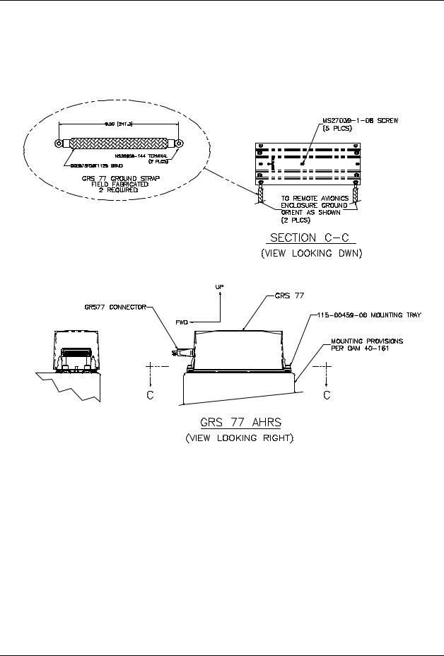
2.1.8GRS 77 Attitude & Heading Reference System
The Garmin GRS 77 AHRS provides attitude and heading information to the G1000 system. The unit is mounted remotely in the baggage compartment, to the starboard side of the remote avionics enclosure (see Figure 2-4 and Figure 2-6). Power is received from the ‘Essential’ bus. The GRS 77 interfaces with and provides power to the GMU 44 Magnetometer. The GRS 77 supplies attitude and heading information directly to the PFD, MFD, and to both GIAs.
Figure 2-4. GRS 77 Mount
Page 2-6 |
G1000/DA40 System Maintenance Manual |
Revision 6 |
190-00303-03 |
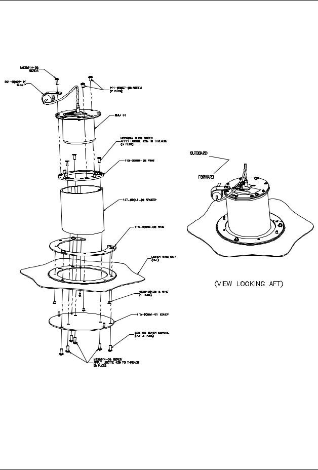
2.1.9GMU 44 Magnetometer
The GMU 44 provides horizontal and vertical magnetic field information to the GRS 77 AHRS. This allows heading to be calculated and provides assistance during AHRS alignment. The GMU 44 is mounted beneath the starboard wing as shown in Figure 2-5 and Figure 2-6.
Figure 2-5. GMU 44 Installation
G1000/DA40 System Maintenance Manual |
Page 2-7 |
190-00303-03 |
Revision 6 |

2.2Equipment Locations
GDC 74A
Figure 2-6. G1000 in DA 40 Equipment Locations
Page 2-8 |
G1000/DA40 System Maintenance Manual |
Revision 6 |
190-00303-03 |
2.3Remote Avionics Enclosure
A remote avionics enclosure allows LRUs to be inserted vertically, from above. The enclosure is also cooled with an avionics fan and duct assembly as shown in Figure 2-6 and Figure 2-7. The enclosure is installed as shown in Figure 2-7. The assembly is grounded to an existing grounding station using a fieldfabricated aluminum ground strap. Two braided grounding straps are also attached to the GRS 77 rack from the enclosure. A Comant diplexer is installed on the enclosure as shown. A field-fabricated component bracket with resistors, voltage suppressors and attached wiring is fastened to the forward portion of the enclosure (see Section 2.5).
Figure 2-7. Remote Avionics Enclosure
G1000/DA40 System Maintenance Manual |
Page 2-9 |
190-00303-03 |
Revision 6 |

Figure 2-7. Remote Avionics Enclosure, Cont.
Page 2-10 |
G1000/DA40 System Maintenance Manual |
Revision 6 |
190-00303-03 |

2.4 Electrical Power Distribution
Distribution of power to the G1000 occurs on three buses:
Essential Bus: The ‘Essential’ bus is tied directly to the aircraft battery via the master switch. When the master switch is turned on, power is immediately supplied the ‘Essential’ bus. The ‘Essential’ bus is tied via a relay switch to the ‘Main’ aircraft bus. There are two circuit breakers on either side of the relay, combined with a single diode, allowing the battery to be charged by the alternator. Only equipment deemed essential for safe flight is connected to this bus.
Main Aircraft Bus: The ‘Main’ bus receives power from the aircraft battery when tied to the ‘Essential’ bus. After the aircraft engine is started, the alternator supplies power to the aircraft ‘Main’ bus, and to the rest of the system. In the event of an alternator or other power failure, the ‘Essential’ bus can be isolated with the ‘Essential Bus’ switch. This causes the ‘Essential’ bus to revert to battery power. Only the MFD receives power from the ‘Main’ bus.
Main Avionics Bus: A ‘Main Avionics’ bus is tied to the ‘Main’ aircraft bus via the ‘Avionics Master’ switch and switch relay. Only the #2 GIA 63 and the GMA 1347 are connected to this bus.
Figure 2-8. G1000/DA40 Electrical Distribution
G1000/DA40 System Maintenance Manual |
Page 2-11 |
190-00303-03 |
Revision 6 |
2.5Lightning Strike Protection
The following modifications to the aircraft provide additional protection of G1000 equipment from the effects of lightning strike.
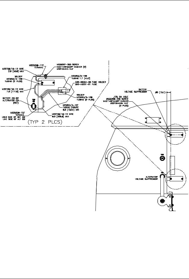
2.5.1Alternator / Battery Voltage Suppressors & Fuses
Two Transient Voltage Suppressors (TVS) are installed behind the instrument panel near the circuit breakers. Voltage suppressors help protect the avionics/electrical equipment against the effects of lighting strike. One voltage suppressor is connected to the load side of the aircraft battery circuit breaker, and the other is connected to the line side of the alternator circuit breaker. One 3.2 Amp slow-blow fuse is wired in line with each voltage suppressor, as shown in Figure 2-9. Fuses are easily removed by twisting the fuse holder cap counter-clockwise and removing the fuse.
Figure 2-9. TVS & Fuse Installation
Page 2-12 |
G1000/DA40 System Maintenance Manual |
Revision 6 |
190-00303-03 |

2.5.2GIA / AHRS Lightning Protection
The GRS 77 and both GIA 63s are uniquely protected from the effects of lightning. A 0.499Ω resistor, a transient voltage suppressor, and a 3.2 Amp slow-blow fuse are used for each GIA and the AHRS. These components are installed on a field-fabricated aluminum block, which is mounted to the front of the remote avionics enclosure (see Figure 2-7 and Figure 2-10). The dimensions for the mounting block are provided in Figure 2-11. Power leads for the AHRS and both GIAs are routed from the aircraft harness to a 9-pin connector (P900), whose mating connector is mounted to the fabricated block (J900). Figure 2-12 shows the wiring setup on the block for one set of components. Power is returned to the LRU after passing through the resistor and voltage suppressor.
Figure 2-10. Lightning Protection Components
Figure 2-11. Component Plate Dimensions
G1000/DA40 System Maintenance Manual |
Page 2-13 |
190-00303-03 |
Revision 6 |
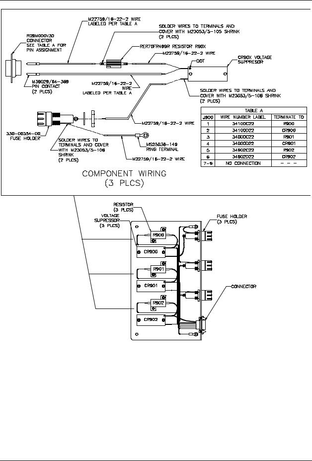
Figure 2-12. Component Wiring Diagram
Page 2-14 |
G1000/DA40 System Maintenance Manual |
Revision 6 |
190-00303-03 |

2.5.3Lightning Strike Maintenance
Proper electrical bonding of all metallic components is critical for the protection against the effects of lighting. Severe corrosion may inhibit a component’s ability to bond to the aircraft’s electrical ground plane. The following summarizes maintenance practices which are implemented to maintain adequate lightning protection for the aircraft. See Section 4, Table 4-1 for exact maintenance requirements and associated intervals:
•A 1000-hour visual inspection of all G1000 equipment, including voltage suppressors, resistors, fuses, etc.
•An electrical bonding check of G1000 equipment every 1000 hours or anytime a lightning strike occurs or is suspected.
•Regular replacement (every 2 years) of all five 3.2 Amp slow-blow fuses ensures they are in fresh condition.
•Replacement of voltage suppressors, resistors, and fuses anytime a lightning strike occurs or is suspected.
G1000/DA40 System Maintenance Manual |
Page 2-15 |
190-00303-03 |
Revision 6 |

2.6SPIDER Grounds
Most G1000 connectors employ a SPIDER grounding system to provide necessary ground reference to shielding and/or transducers. A single 16-gauge wire is connected locally to the airframe. Additional ‘spider’ wires, 24-gauge, are used to connect shield grounds. The assembly is fastened directly to the backshell housing with two screws. Figure 2-13 shows an example SPIDER installation.
Figure 2-13. SPIDER Ground Installation
Page 2-16 |
G1000/DA40 System Maintenance Manual |
Revision 6 |
190-00303-03 |

2.7Sensor Installations
2.7.1Manifold Air Pressure
A Kulite MAP sensor measures manifold air pressure. The sensor, manifold hose, and adapter fittings are installed as shown in Figure 2-14.
Figure 2-14. MAP Sensor
2.7.2Oil Pressure
A Kulite pressure sensor measures oil pressure. The sensor, oil pressure hose, and fittings are installed as shown in Figure 2-15.
Figure 2-15. Oil Pressure Sensor
2.7.3Oil Temperature
A Norwich Aero Products oil temperature sensor is used to measure oil temperature. The sensor is installed as shown in Figure 2-16.
G1000/DA40 System Maintenance Manual |
Page 2-17 |
190-00303-03 |
Revision 6 |

Figure 2-16. Oil Temperature Sensor
2.7.4Fuel Pressure
A Kulite pressure sensor is used to measure fuel pressure. The sensor, fuel hose, O-rings, and associated fittings are installed as shown in Figure 2-17.
Figure 2-17. Fuel Pressure Sensor
2.7.5Tachometer
A tachometer provides engine RPM measurements to the G1000 system. The tachometer is installed as shown in Figure 2-18.
Page 2-18 |
G1000/DA40 System Maintenance Manual |
Revision 6 |
190-00303-03 |
 Loading...