


 Loading...
G1000® Integrated Flight Deck
Pilot’s Guide
Cessna Caravan

SYSTEM OVERVIEW
FLIGHT INSTRUMENTS
EIS
AUDIO PANEL & CNS
FLIGHT MANAGEMENT
HAZARD AVOIDANCE
AFCS
ADDITIONAL FEATURES
APPENDICES
INDEX

Copyright © 2008 Garmin Ltd. or its subsidiaries. All rights reserved.
This manual reflects the operation of System Software version 0767.00 or later for the Cessna Caravan. Some differences in operation may be observed when comparing the information in this manual to earlier or later software versions.
Garmin International, Inc., 1200 East 151st Street, Olathe, Kansas 66062, U.S.A.
Tel: 913/397.8200 |
Fax: 913/397.8282 |
Garmin AT, Inc., 2345 Turner Road SE, Salem, OR 97302, U.S.A. |
|
Tel: 503/391.3411 |
Fax 503/364.2138 |
Garmin (Europe) Ltd., Liberty House, Hounsdown Business Park, Southampton, SO40 9RB, U.K. |
|
Tel: 44/0870.851241 |
Fax: 44/0870.8501251 |
Garmin Corporation, No. 68, Jangshu 2nd Road, Shijr,Taipei County,Taiwan |
|
Tel: 886/02.2642.9199 |
Fax: 886/02.2642.9099 |
Web Site Address: www.garmin.com
Except as expressly provided herein, no part of this manual may be reproduced, copied, transmitted, disseminated, downloaded or stored in any storage medium, for any purpose without the express written permission of Garmin. Garmin hereby grants permission to download a single copy of this manual and of any revision to this manual onto a hard drive or other electronic storage medium to be viewed for personal use,provided that such electronic or printed copy of this manual or revision must contain the complete text of this copyright notice and provided further that any unauthorized commercial distribution of this manual or any revision hereto is strictly prohibited.
Garmin®and G1000® are registered trademarks of Garmin Ltd.or its subsidiaries. WATCH™,FliteCharts™,and SafeTaxi™ are trademarks of Garmin Ltd. or its subsidiaries. These trademarks may not be used without the express permission of Garmin.
Bendix/King® and Honeywell® are registered trademarks of Honeywell International, Inc.; Becker® is a registered trademark of Becker Flugfunkwerk GmbH; NavData® is a registered trademark of Jeppesen, Inc.; XM® is a registered trademark of XM Satellite Radio, Inc.
January 2008 |
190-00749-00 Rev. B |
Printed in the U.S.A. |
Garmin G1000 Pilot’s Guide for the Cessna Caravan |
190-00749-00 Rev. B |

LIMITED WARRANTY
LIMITED WARRANTY
This Garmin product is warranted to be free from defects in materials or workmanship for two years from the date of purchase. Within this period, Garmin will, at its sole option, repair or replace any components that fail in normal use. Such repairs or replacement will be made at no charge to the customer for parts and labor,provided that the customer shall be responsible for any transportation cost. This warranty does not cover failures due to abuse, misuse, accident, or unauthorized alterations or repairs.
THE WARRANTIES AND REMEDIES CONTAINED HEREIN ARE EXCLUSIVE AND IN LIEU OF ALL OTHER WARRANTIES EXPRESS OR IMPLIED OR STATUTORY, INCLUDING ANY LIABILITY ARISING UNDER ANY WARRANTY OF MERCHANTABILITY OR FITNESS FOR A PARTICULAR PURPOSE, STATUTORY OR OTHERWISE. THIS WARRANTY GIVES YOU SPECIFIC LEGAL RIGHTS, WHICH MAY VARY FROM STATE TO STATE.
IN NO EVENT SHALL GARMIN BE LIABLE FOR ANY INCIDENTAL, SPECIAL, INDIRECT OR CONSEQUENTIAL DAMAGES, WHETHER RESULTING FROM THE USE, MISUSE, OR INABILITY TO USE THIS PRODUCT OR FROM DEFECTS IN THE PRODUCT. Some states do not allow the exclusion of incidental or consequential damages, so the above limitations may not apply to you.
Garmin retains the exclusive right to repair or replace the unit or software, or to offer a full refund of the purchase price, at its sole discretion. SUCH REMEDY SHALL BE YOUR SOLE AND EXCLUSIVE REMEDY FOR ANY BREACH OF WARRANTY.
To obtain warranty service, contact your local GarminAuthorized Service Center. For assistance in locating a Service Center near you, visit the Garmin Web site at “http://www.garmin.com” or contact Garmin Customer Service at 800-800-1020.
190-00749-00 Rev. B |
Garmin G1000 Pilot’s Guide for the Cessna Caravan |
i |

WARNINGS, CAUTIONS, AND NOTES
WARNING: Navigation and terrain separation must NOT be predicated upon the use of the terrain function. The G1000Terrain Proximity feature is NOT intended to be used as a primary reference for terrain avoidance and does not relieve the pilot from the responsibility of being aware of surroundings during flight. The Terrain Proximity feature is only to be used as an aid for terrain avoidance and is not certified for use in applications requiring a certified terrain awareness system. Terrain data is obtained from third party sources. Garmin is not able to independently verify the accuracy of the terrain data.
WARNING: The displayed minimum safe altitudes (MSAs) are only advisory in nature and should not be relied upon as the sole source of obstacle and terrain avoidance information. Always refer to current aeronautical charts for appropriate minimum clearance altitudes.
WARNING: The altitude calculated by G1000 GPS receivers is geometric height above Mean Sea Level and could vary significantly from the altitude displayed by pressure altimeters, such as the GDC 74A Air Data Computer, or other altimeters in aircraft. GPS altitude should never be used for vertical navigation. Always use pressure altitude displayed by the G1000 PFD or other pressure altimeters in aircraft.
WARNING:Donotuseoutdateddatabaseinformation.DatabasesusedintheG1000systemmustbeupdated regularly in order to ensure that the information remains current. Pilots using any outdated database do so entirely at their own risk.
WARNING: Do not use basemap (land and water data) information for primary navigation. Basemap data is intended only to supplement other approved navigation data sources and should be considered as an aid to enhance situational awareness.
WARNING: Traffic information shown on the G1000 Multi Function Display is provided as an aid in visually acquiring traffic. Pilots must maneuver the aircraft based only upon ATC guidance or positive visual acquisition of conflicting traffic.
WARNING: XM Weather should not be used for hazardous weather penetration. Weather information provided by the GDL 69 is approved only for weather avoidance, not penetration.
WARNING: NEXRAD weather data is to be used for long-range planning purposes only. Due to inherent delays in data transmission and the relative age of the data, NEXRAD weather data should not be used for short-range weather avoidance.
WARNING: The Garmin G1000, as installed in the Cessna Caravan aircraft, has a very high degree of functional integrity. However, the pilot must recognize that providing monitoring and/or self-test capability for all conceivable system failures is not practical. Although unlikely, it may be possible for erroneous operation to occur without a fault indication shown by the G1000. It is thus the responsibility of the pilot to detect such an occurrence by means of cross-checking with all redundant or correlated information available in the cockpit.
 WARNING: For safety reasons, G1000 operational procedures must be learned on the ground.
ii |
Garmin G1000 Pilot’s Guide for the Cessna Caravan |
190-00749-00 Rev. B |
WARNINGS, CAUTIONS, AND NOTES
WARNING: The United States government operates the Global Positioning System and is solely responsible for its accuracy and maintenance. The GPS system is subject to changes which could affect the accuracy and performance of all GPS equipment. Portions of the Garmin G1000 utilize GPS as a precision electronic NAVigation AID (NAVAID). Therefore, as with all NAVAIDs, information presented by the G1000 can be misused or misinterpreted and, therefore, become unsafe.
WARNING: To reduce the risk of unsafe operation, carefully review and understand all aspects of the G1000 Pilot’s Guide documentation and the Cessna Caravan Pilot’s Operating Handbook. Thoroughly practice basic operation prior to actual use. During flight operations, carefully compare indications from the G1000 to all available navigation sources, including the information from other NAVAIDs, visual sightings, charts, etc. For safety purposes, always resolve any discrepancies before continuing navigation.
WARNING: The illustrations in this guide are only examples. Never use the G1000 to attempt to penetrate a thunderstorm. Both the FAA Advisory Circular, Subject:Thunderstorms, and the Aeronautical Information Manual (AIM) recommend avoiding“by at least 20 miles any thunderstorm identified as severe or giving an intense radar echo.”
CAUTION: The PFD and MFD displays use a lens coated with a special anti-reflective coating that is very sensitive to skin oils, waxes, and abrasive cleaners. CLEANERS CONTAINING AMMONIA WILL HARM THE ANTI-REFLECTIVE COATING. It is very important to clean the lens using a clean, lint-free cloth and an eyeglass lens cleaner that is specified as safe for anti-reflective coatings.
CAUTION: The Garmin G1000 does not contain any user-serviceable parts. Repairs should only be made by an authorized Garmin service center. Unauthorized repairs or modifications could void both the warranty and the pilot’s authority to operate this device under FAA/FCC regulations.
NOTE: All visual depictions contained within this document,including screen images of the G1000 panel and displays, are subject to change and may not reflect the most current G1000 system and aviation databases. Depictions of equipment may differ slightly from the actual equipment.
NOTE:Thisdevicecomplieswithpart15oftheFCCRules. Operationissubjecttothefollowingtwoconditions:
(1) this device may not cause harmful interference,and (2) this device must accept any interference received, including interference that may cause undesired operation.
NOTE: This product, its packaging, and its components contain chemicals known to the State of California to cause cancer, birth defects, or reproductive harm. This notice is being provided in accordance with California’s Proposition 65. If you have any questions or would like additional information, please refer to our web site at www.garmin.com/prop65.
 NOTE: Interference from GPS repeaters operating inside nearby hangars can cause an intermittent loss of attitude and heading displays while the aircraft is on the ground. Moving the aircraft more than 100 feet away from the source of the interference should alleviate the condition.
190-00749-00 Rev. B |
Garmin G1000 Pilot’s Guide for the Cessna Caravan |
iii |

REVISION INFORMATION
|
|
|
Record of Revisions |
|
|
|
|
|
|
Part Number |
Revision |
Date |
Page Range |
Description |
190-00749-00 |
A |
January, 2008 |
All |
Initial release |
|
B |
January, 2008 |
Copyright Page |
Correct system software number |
|
|
|
|
|
iv |
Garmin G1000 Pilot’s Guide for the Cessna Caravan |
190-00749-00 Rev. B |

TABLE OF CONTENTS
|
SECTION 1 SYSTEM OVERVIEW |
|
1.1 |
System Description................................................. |
1 |
1.2 |
Line Replaceable Units (LRU)................................. |
2 |
1.3 |
G1000 Controls........................................................ |
7 |
|
PFD/MFD Controls ........................................................ |
7 |
|
AFCS Controls.............................................................. |
9 |
|
Audio Panel Controls .................................................. |
11 |
1.4 |
Secure Digital Cards ............................................. |
13 |
1.5 |
System Power-up................................................... |
14 |
1.6 |
System Operation.................................................. |
15 |
|
Normal Operation....................................................... |
15 |
|
Reversionary Mode..................................................... |
15 |
|
AHRS Operation ......................................................... |
16 |
|
G1000 SystemAnnunciations ...................................... |
18 |
|
Softkey Function......................................................... |
19 |
|
GPS Receiver Operation .............................................. |
26 |
1.7 |
Accessing G1000 Functionality ........................... |
30 |
|
Menus....................................................................... |
30 |
|
MFD Page Groups....................................................... |
31 |
|
MFD System Pages ..................................................... |
37 |
1.8 |
Display Backlighting............................................. |
45 |
|
AutomaticAdjustment ................................................ |
45 |
|
ManualAdjustment .................................................... |
45 |
|
SECTION 2 FLIGHT INSTRUMENTS |
|
2.1 |
Flight Instruments................................................. |
50 |
|
Airspeed Indicator ...................................................... |
50 |
|
Attitude Indicator....................................................... |
52 |
|
Altimeter ................................................................... |
53 |
|
Vertical Speed Indicator (VSI)....................................... |
57 |
|
Vertical Deviation....................................................... |
57 |
|
Horizontal Situation Indicator (HSI) .............................. |
58 |
|
Course Deviation Indicator (cdi)................................... |
63 |
2.2 |
Supplemental Flight Data .................................... |
71 |
|
Temperature displays.................................................. |
71 |
|
Wind Data ................................................................. |
72 |
|
Vertical Navigation (VNV) Indications........................... |
73 |
2.3 |
PFD Annunciations and Alerting Functions........ |
74 |
|
SystemAlerting.......................................................... |
74 |
|
Marker BeaconAnnunciations ..................................... |
76 |
|
TrafficAnnunciation (optional)..................................... |
76 |
|
TAWSAnnunciations (optional).................................... |
77 |
|
AltitudeAlerting......................................................... |
78 |
|
LowAltitudeAnnunciation .......................................... |
78 |
|
Minimum DescentAltitude/Decision HeightAlerting ...... |
79 |
2.4 |
Abnormal Operations ........................................... |
81 |
|
Abnormal GPS Conditions ........................................... |
81 |
|
UnusualAttitudes....................................................... |
82 |
|
SECTION 3 ENGINE INDICATION SYSTEM (EIS) |
|
3.1 |
Engine Display....................................................... |
86 |
3.2 |
System Display ...................................................... |
88 |
|
Fuel Calculations........................................................ |
91 |
|
SECTION 4 AUDIO PANEL AND CNS |
|
4.1 |
Overview................................................................ |
93 |
|
MFD/PFD Controls and Frequency Display..................... |
94 |
|
Audio Panel Controls .................................................. |
96 |
4.2 |
COM Operation...................................................... |
98 |
|
COMTransceiver Selection andActivation..................... |
98 |
|
COMTransceiver ManualTuning .................................. |
99 |
|
Quick-Tuning andActivating 121.500 MHz.................. |
100 |
|
Auto-Tuning the COM Frequency................................ |
101 |
|
Frequency Spacing.................................................... |
105 |
|
Automatic Squelch.................................................... |
106 |
|
Volume.................................................................... |
106 |
4.3 |
NAV Operation..................................................... |
107 |
|
NAV Radio Selection andActivation ........................... |
107 |
|
NAV Receiver ManualTuning..................................... |
108 |
|
Auto-Tuning a NAV Frequency from the MFD .............. |
110 |
|
Marker Beacon Receiver............................................ |
115 |
|
DMETuning ............................................................. |
116 |
4.4 GTX 33 Mode S Transponder.............................. |
117 |
|
|
Transponder Controls................................................ |
117 |
|
Transponder Mode Selection...................................... |
119 |
|
Entering aTransponder Code..................................... |
121 |
|
IDENT Function ........................................................ |
122 |
|
Flight ID Reporting ................................................... |
123 |
4.5 |
Additional Audio Panel Functions..................... |
124 |
|
Power-Up................................................................. |
124 |
|
Mono/Stereo Headsets.............................................. |
124 |
|
Speaker ................................................................... |
124 |
|
Intercom.................................................................. |
125 |
190-00749-00 Rev. B |
Garmin G1000 Pilot’s Guide for the Cessna Caravan |
v |

TABLE OF CONTENTS
|
PassengerAddress (PA) System.................................. |
127 |
|
Clearance Recorder and Player................................... |
127 |
|
Entertainment Inputs................................................ |
128 |
4.6 Audio Panel Preflight Procedure....................... |
129 |
|
4.7 |
Abnormal Operation........................................... |
130 |
|
Stuck Microphone..................................................... |
130 |
|
COMTuning Failure................................................... |
130 |
|
PFD Failure, Dual System........................................... |
131 |
|
Audio Panel Fail-Safe Operation................................. |
132 |
|
Reversionary Mode................................................... |
132 |
|
SECTION 5 FLIGHT MANAGEMENT |
|
5.1 |
Introduction......................................................... |
133 |
|
Navigation Status Box............................................... |
135 |
5.2 |
Using Map Displays............................................. |
136 |
|
Map Orientation....................................................... |
136 |
|
Map Range.............................................................. |
138 |
|
Map Panning............................................................ |
141 |
|
Measuring Bearing and Distance................................ |
145 |
|
Topography.............................................................. |
146 |
|
Map Symbols ........................................................... |
149 |
|
Airways ................................................................... |
155 |
|
TrackVector ............................................................. |
157 |
|
WindVector............................................................. |
158 |
|
Nav Range Ring ....................................................... |
159 |
|
Fuel Range Ring....................................................... |
160 |
5.3 |
Waypoints............................................................. |
161 |
|
Airports................................................................... |
162 |
|
Intersections ............................................................ |
168 |
|
NDBs....................................................................... |
170 |
|
VORs....................................................................... |
172 |
|
UserWaypoints ........................................................ |
174 |
5.4 |
Airspaces.............................................................. |
178 |
5.5 Direct-to-Navigation .......................................... |
182 |
|
5.6 |
Flight Planning..................................................... |
187 |
|
Flight Plan Creation.................................................. |
188 |
|
AddingWaypoints to an Existing Flight Plan................ |
191 |
|
AddingAirways to a Flight Plan ................................. |
193 |
|
Adding Procedures to a Stored Flight Plan .................. |
195 |
|
Flight Plan Storage ................................................... |
201 |
|
Flight Plan Editing .................................................... |
204 |
|
AlongTrack Offsets................................................... |
207 |
|
ParallelTrack............................................................ |
209 |
|
Activating a Flight Plan Leg....................................... |
212 |
|
Inverting a Flight Plan............................................... |
213 |
|
Flight PlanViews...................................................... |
214 |
|
Closest Point of FPL .................................................. |
216 |
5.7 |
Vertical Navigation............................................. |
217 |
|
Altitude Constraints.................................................. |
219 |
5.8 |
Procedures ........................................................... |
223 |
|
Departures............................................................... |
223 |
|
Arrivals ................................................................... |
226 |
|
Approaches ............................................................. |
228 |
5.9 |
Trip Planning........................................................ |
234 |
|
Trip Planning............................................................ |
234 |
5.10 |
RAIM Prediction .................................................. |
238 |
5.11 |
Navigating a Flight Plan..................................... |
241 |
5.12 |
Abnormal Operation........................................... |
268 |
|
SECTION 6 HAZARD AVOIDANCE |
|
6.1 |
XM Satellite Weather.......................................... |
271 |
|
Activating Services.................................................... |
272 |
|
Using XM SatelliteWeather Products.......................... |
273 |
6.2 |
Airborne Color Weather Radar.......................... |
296 |
|
System Description ................................................... |
296 |
|
Principles of PulsedAirborneWeather Radar............... |
296 |
|
Safe Operating Distance............................................ |
301 |
|
BasicAntennaTilt Setup............................................ |
301 |
|
Weather Mapping and Interpretation ......................... |
303 |
|
Ground Mapping and Interpretation........................... |
316 |
6.3 |
WX-500 Stormscope ........................................... |
317 |
|
Setting Up Stormscope on the Navigation Map ........... |
317 |
|
Selecting the Stormscope Page .................................. |
321 |
6.4 |
Terrain Proximity................................................. |
322 |
|
DisplayingTerrain Proximity Data............................... |
323 |
|
Terrain Proximity Page............................................... |
325 |
6.5 |
TerrainAwareness andWarning System (TAWS)327 |
|
|
DisplayingTAWS Data............................................... |
328 |
|
TAWS Page .............................................................. |
330 |
|
TAWSAlerts............................................................. |
332 |
|
System Status........................................................... |
338 |
6.6 |
Traffic Advisory System (TAS) ............................ |
339 |
|
TAS Symbology......................................................... |
339 |
vi |
Garmin G1000 Pilot’s Guide for the Cessna Caravan |
190-00749-00 Rev. B |

TABLE OF CONTENTS
|
Operation ................................................................ |
340 |
|
DisplayingTraffic Data .............................................. |
340 |
|
Altitude Display........................................................ |
343 |
|
Traffic Map Page Display Range................................. |
343 |
|
TASAlerts................................................................ |
345 |
|
System Status........................................................... |
345 |
SECTION 7 AUTOMATIC FLIGHT CONTROL SYSTEM |
||
7.1 |
AFCS Controls...................................................... |
348 |
|
AdditionalAFCS Controls .......................................... |
349 |
7.2 |
Flight Director Operation................................... |
350 |
|
Activating the Flight Director..................................... |
350 |
|
AFCS Status Box....................................................... |
351 |
|
Flight Director Modes................................................ |
352 |
|
Switching Flight Directors.......................................... |
352 |
|
Command Bars......................................................... |
353 |
7.3 |
Vertical Modes..................................................... |
354 |
|
Pitch Hold Mode (PIT)............................................... |
355 |
|
SelectedAltitude Capture Mode (ALTS)....................... |
356 |
|
Altitude Hold Mode (ALT).......................................... |
357 |
|
Vertical Speed Mode (VS).......................................... |
358 |
|
Flight Level Change Mode (FLC)................................. |
359 |
|
Vertical Navigation Modes (VPTH,ALTV)..................... |
361 |
|
Glidepath Mode (GP) (waas only)............................... |
366 |
|
Glideslope Mode (GS)............................................... |
367 |
|
Takeoff (TO) and GoAround (GA) Modes .................... |
368 |
7.4 |
Lateral Modes...................................................... |
369 |
|
Roll Hold Mode (ROL) ............................................... |
370 |
|
Low Bank Mode....................................................... |
370 |
|
Heading Select Mode (HDG)...................................... |
371 |
|
Navigation Mode (GPS,VOR, LOC) ............................. |
372 |
|
Approach Mode (GPS,VAPP, LOC) .............................. |
374 |
|
Backcourse Mode (BC).............................................. |
376 |
7.5 Autopilot and Yaw Damper Operation............. |
377 |
|
|
Flight Control........................................................... |
377 |
|
Engagement............................................................. |
378 |
|
ControlWheel Steering ............................................. |
378 |
|
Disengagement........................................................ |
379 |
7.6 |
Example Flight Plan ............................................ |
380 |
|
Departure ................................................................ |
381 |
|
Intercepting aVOR Radial.......................................... |
383 |
|
Flying a Flight Plan/GPS Course ................................. |
384 |
|
Descent ................................................................... |
385 |
|
Approach................................................................. |
389 |
|
GoAround/MissedApproach ..................................... |
391 |
7.7 |
AFCS Annunciations and Alerts ......................... |
393 |
|
AFCS StatusAlerts.................................................... |
393 |
|
Overspeed Protection................................................ |
394 |
|
SECTION 8 ADDITIONAL FEATURES |
|
8.1 |
SafeTaxi................................................................ |
395 |
|
SafeTaxi Cycle Number and Revision .......................... |
398 |
8.2 |
ChartView............................................................. |
401 |
|
ChartView Softkeys................................................... |
401 |
|
Terminal Procedures Charts ....................................... |
402 |
|
Chart Options........................................................... |
412 |
|
Day/NightView ........................................................ |
418 |
|
ChartView Cycle Number and Expiration Date............. |
420 |
8.3 |
FliteCharts............................................................ |
424 |
|
FliteCharts Softkeys .................................................. |
424 |
|
Terminal Procedures Charts ....................................... |
425 |
|
Chart Options........................................................... |
433 |
|
Day/NightView ........................................................ |
437 |
|
FliteCharts Cycle Number and Expiration Date............. |
439 |
8.4 |
XM Radio Entertainment.................................... |
443 |
|
Activating XM Satellite Radio Services........................ |
443 |
|
Using XM Radio ....................................................... |
445 |
8.5 |
Scheduler.............................................................. |
449 |
8.6 |
Abnormal Operation........................................... |
451 |
|
APPENDICES |
|
Annunciations and Alerts............................................. |
453 |
|
|
Alert Level Definitions............................................... |
455 |
|
ComparatorAnnunciations........................................ |
456 |
|
Reversionary SensorAnnunciations............................ |
456 |
|
Caravan CASAlerts................................................... |
457 |
|
G1000 SystemAnnunciations .................................... |
459 |
|
G1000 System MessageAdvisories............................. |
461 |
|
AFCSAlerts.............................................................. |
472 |
|
TAWSALERTS........................................................... |
473 |
SD Card Use................................................................... |
475 |
|
|
Jeppesen Databases.................................................. |
475 |
|
Garmin Databases.................................................... |
476 |
Glossary.......................................................................... |
479 |
|
190-00749-00 Rev. B |
Garmin G1000 Pilot’s Guide for the Cessna Caravan |
vii |
TABLE OF CONTENTS
Frequently Asked Questions........................................ |
485 |
Display Symbols............................................................ |
491 |
INDEX |
|
Index ................................................................................ |
I-1 |
viii |
Garmin G1000 Pilot’s Guide for the Cessna Caravan |
190-00749-00 Rev. B |

SYSTEM OVERVIEW
SECTION 1 SYSTEM OVERVIEW
1.1 SYSTEM DESCRIPTION
This section provides an overview of the G1000 Integrated Flight Deck as installed in the Cessna Caravan. The G1000 system is an integrated flight control system that presents flight instrumentation, position, navigation, communication, and identification information to the pilot through large-format displays. The system consists of the following Line Replaceable Units (LRUs):
• GDU 1040A Primary Flight Display (PFD) |
• GTX 33 Mode S Transponder |
• GDU 1040A Multi Function Display (MFD) |
• GDL 69A Satellite Data Link Receiver |
• GIA 63W Integrated Avionics Unit |
• GWX 68 Weather Radar |
• GDC 74A Air Data Computer (ADC) |
• GMC 710 AFCS Control Unit |
• GEA 71 Engine/Airframe Unit |
• GTP 59 Outside Air Temperature (OAT) Probe |
• GRS 77 Attitude and Heading Reference System |
• GSA 80 and GSA 81 AFCS Servos |
(AHRS) |
• GSM 85 and GSM 85A Servo Mounts |
|
•GMU 44 Magnetometer
•GMA 1347 Audio System with Integrated Marker Beacon Receiver
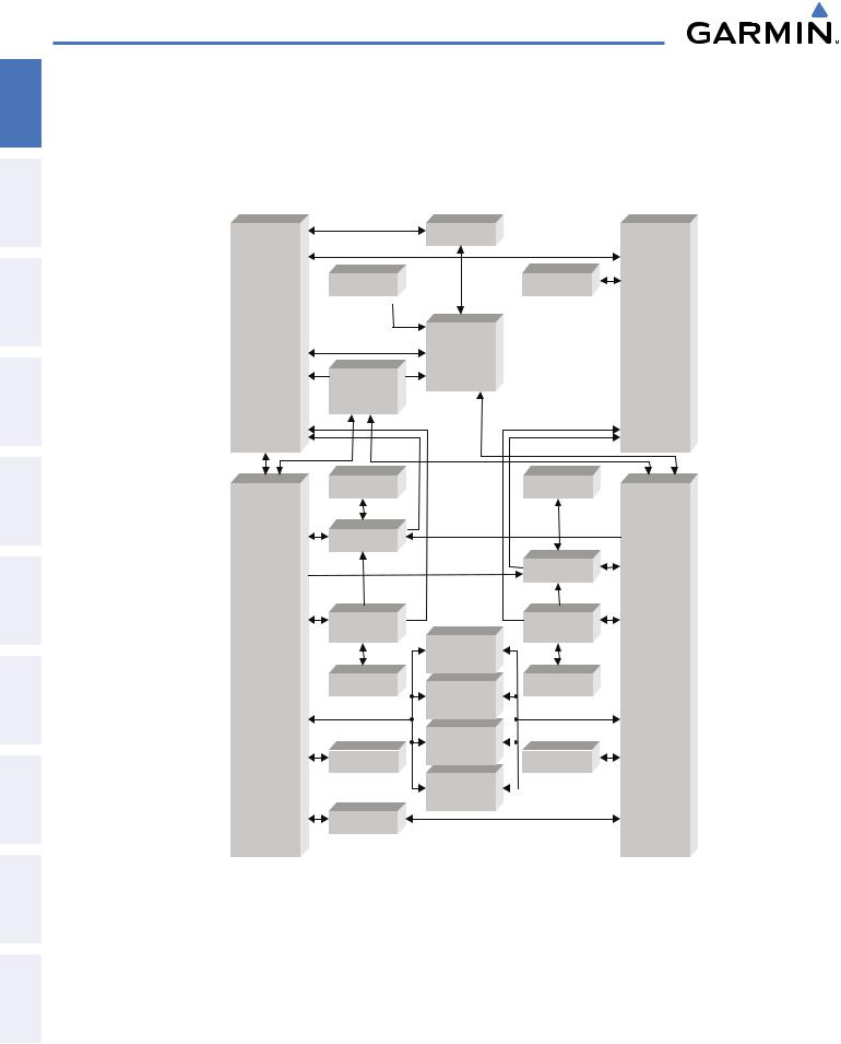
A top-level G1000 system block diagram is shown in Figure 1-1 (it does not include the GSM 85 or 85A).
 NOTE: Refer to the AFCS section for details on the GFC 700 AFCS.
In the Cessna Caravan, the GFC 700 Automated Flight Control System (AFCS) provides the flight director (FD), autopilot (AP), and yaw damper (YD) functions of the G1000 system.
INDEX APPENDICES ADDITIONALFEATURES AFCS AVOIDANCEHAZARD MANAGEMENTFLIGHT PANELCNSAUDIO& EIS INSTRUMENTSFLIGHT OVERVIEWSYSTEM
190-00749-00 Rev. B |
Garmin G1000 Pilot’s Guide for the Cessna Caravan |
1 |
ADDITIONAL HAZARD FLIGHT AUDIO PANEL FLIGHT SYSTEM INDEX APPENDICES FEATURES AFCS AVOIDANCE MANAGEMENT & CNS EIS INSTRUMENTS OVERVIEW
SYSTEM OVERVIEW
1.2 LINE REPLACEABLE UNITS (LRU)
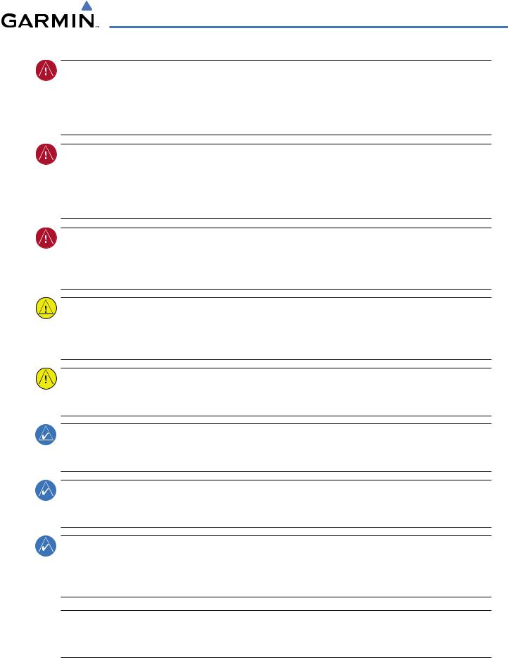
•GDU1040A(3) – Each of the PFDs and the MFD feature a 10.4-inch LCD with 1024 x 768 resolution. The unit installed on the left/pilot side is designated as PFD1. The unit installed on the right/co-pilot side is designated as PFD2. The unit installed in the center of the panel is designated as the MFD. These units communicate with each other and with the GIA 63W Integrated Avionics Units through a High-Speed Data Bus (HSDB) connection.
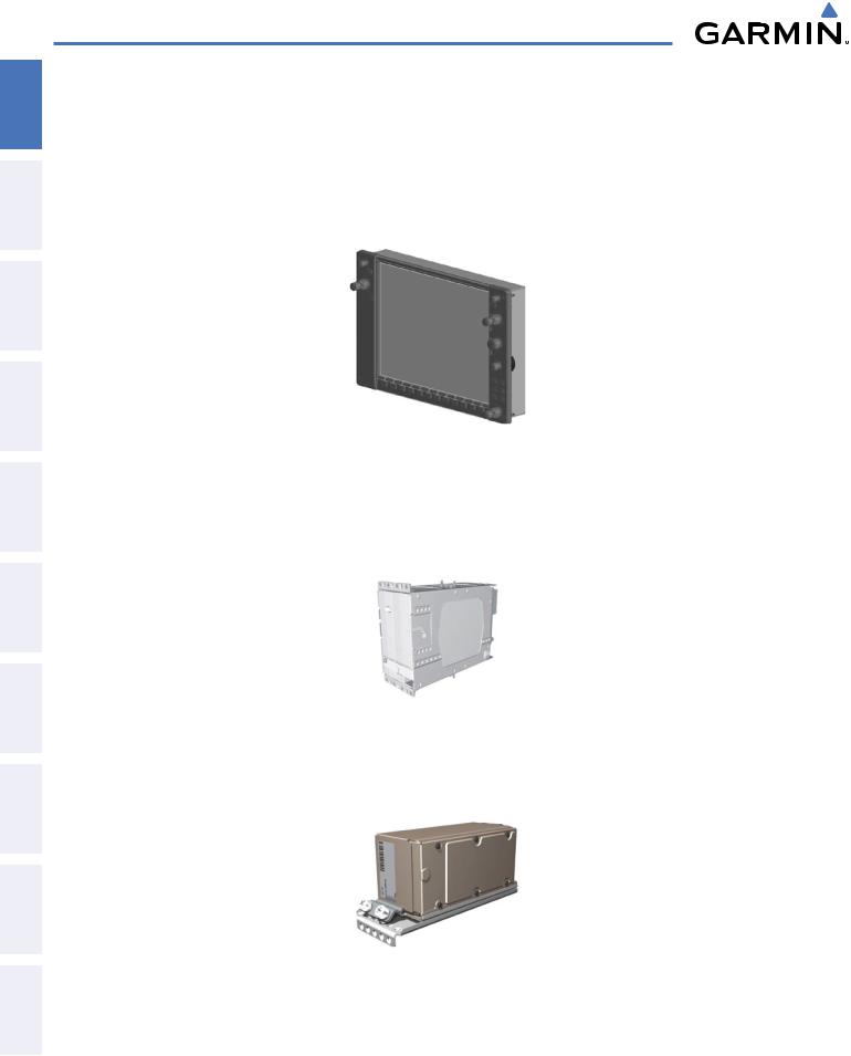
•GIA 63W (2) – Functions as the main communication hub, linking all LRUs with the displays via HSDB connections. Each GIA 63W contains a GPS WAAS receiver, VHF COM/NAV/GS receivers, a flight director (FD) and system integration microprocessors. The GIA 63Ws are not paired together and do not communicate with each other directly.
•GDC74A(2) – Processes data from the pitot/static system as well as the OAT probe. This unit provides pressure altitude, airspeed, vertical speed and OAT information to the G1000 system, and it communicates with the onside GIA 63W, on-side GDU 1040A, on-side GTP59, and on-side GRS 77, using an ARINC 429 digital interface (the pilot’s side GDC 74A also interfaces directly with the MFD).
2 |
Garmin G1000 Pilot’s Guide for the Cessna Caravan |
190-00749-00 Rev. B |
SYSTEM OVERVIEW
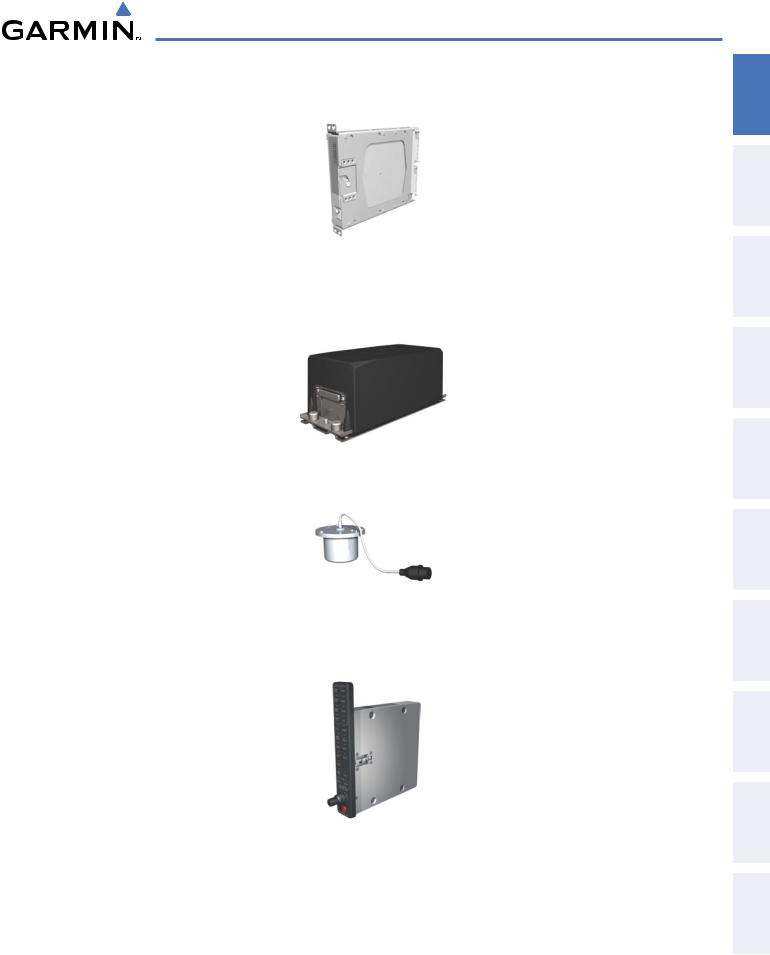
•GEA 71 (1) – Receives and processes signals from the engine and airframe sensors. This unit communicates with both GIA 63Ws using an RS-485 digital interface.
•GRS77(2) – Provides aircraft attitude and heading information via ARINC 429 to both the on-side GDU 1040A and the on-side GIA 63W (the pilot-side GRS 77 also interfaces with the MFD). The GRS 77 contains advanced sensors (including accelerometers and rate sensors) and interfaces with the on-side GMU 44 to obtain magnetic field information, with the GDC 74B to obtain air data, and with both GIA 63Ws to obtain GPS information. AHRS modes of operation are discussed later in this document.
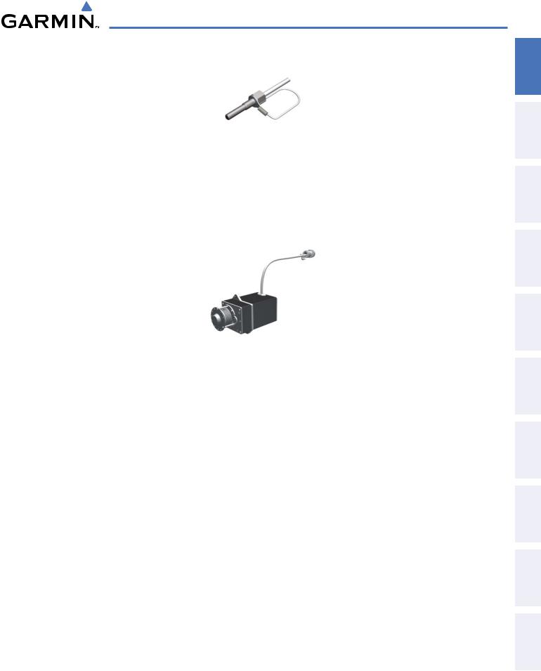
•GMU 44 (2) – Measures local magnetic field. Data is sent to the GRS 77 for processing to determine aircraft magnetic heading. This unit receives power directly from the GRS 77 and communicates with the GRS 77, using an RS-485 and RS-232 digital interface.
•GMA 1347 (1) – Integrates NAV/COM digital audio, intercom system and marker beacon controls, and is installed between PFD1 and the MFD. This unit also enables the manual control of the display reversionary mode (red DISPLAY BACKUP button) and communicates with both GIA 63Ws, using an RS-232 digital interface.
INDEX APPENDICES ADDITIONALFEATURES AFCS AVOIDANCEHAZARD MANAGEMENTFLIGHT PANELCNSAUDIO& EIS INSTRUMENTSFLIGHT OVERVIEWSYSTEM
190-00749-00 Rev. B |
Garmin G1000 Pilot’s Guide for the Cessna Caravan |
3 |

SYSTEM OVERVIEW
ADDITIONAL HAZARD FLIGHT AUDIO PANEL FLIGHT SYSTEM INDEX APPENDICES FEATURES AFCS AVOIDANCE MANAGEMENT & CNS EIS INSTRUMENTS OVERVIEW
•GTX 33 (1 or 2) – Solid-state transponders that provide Modes A, C and S capability. Both transponders can be controlled from either PFD, and only one transponder can be active at a time. Each transponder communicates with the on-side GIA 63W through an RS-232 digital interface.
•GDL 69A (1, optional) – A satellite radio receiver that provides real-time weather information to the G1000 MFD (and, indirectly, to the inset map of the PFD) as well as digital audio entertainment. The GDL 69A communicates with the displays via HSDB connection through PFD2. A subscription to the XM Satellite Radio service is required to enable the GDL 69A capability.
•GWX 68 (1, optional) – Provides airborne weather and ground mapped radar data to the MFD, via HSDB connection.
•GMC 710 (1) – Provides the controls for the GFC 700 AFCS through an RS-232 digital interface allowing communication with the displays.
4 |
Garmin G1000 Pilot’s Guide for the Cessna Caravan |
190-00749-00 Rev. B |
SYSTEM OVERVIEW
•GTP 59 (2) – Provides Outside Air Temperature (OAT) data to the on-side GDC 74A.
•GSA 80 (2), GSA 81(2), GSM 85(1) and GSM 85A(3) – The GSA 80 servos are used for the automatic control of roll and yaw, while the GSA 81 servos are used for the automatic control of pitch and pitch trim. These units interface with each GIA 63W via an RS-485 interface.
The GSM 85 and GSM 85A servo mounts are responsible for transferring the output torque of the GSA 80/81 servo actuator to the mechanical flight-control surface linkage. The GSM 85A servo gearboxes are used when installed in areas that could experience ice or other contamination. The GSM 85 servo gearbox is used for the pitch-trim axis, which is installed in a benign enviroment.
INDEX APPENDICES ADDITIONALFEATURES AFCS AVOIDANCEHAZARD MANAGEMENTFLIGHT PANELCNSAUDIO& EIS INSTRUMENTSFLIGHT OVERVIEWSYSTEM
190-00749-00 Rev. B |
Garmin G1000 Pilot’s Guide for the Cessna Caravan |
5 |
SYSTEM OVERVIEW
ADDITIONAL HAZARD FLIGHT AUDIO PANEL FLIGHT SYSTEM INDEX APPENDICES FEATURES AFCS AVOIDANCE MANAGEMENT & CNS EIS INSTRUMENTS OVERVIEW
GDU 1040A
(PFD #1)
GIA 63W #1
VHF COM
VHF NAV/LOC
GPS/WAAS
G/S
AFCS Mode Logic
Flight Director
Servo Management
GMC 710
GWX 68
(OPTIONAL)
GMA 1347D
#1
GMU 44 #1
GRS 77 #1
GDC 74A #1
GTP 59 #1
GTX 33 #1
GEA 71
GDL 69A
(OPTIONAL)
GDU 1040A
(MFD)
GMU 44 #2
|
|
GRS 77 #2 |
|
|
GDC 74A #2 |
GSA 81 |
|
|
(Pitch Trim) |
|
|
GSA 81 |
|
GTP 59 #2 |
|
|
|
(Pitch) |
|
|
GSA 80 |
|
|
(Roll) |
|
GTX 33 #2 |
|
|
|
GSA 80 |
|
(OPTIONAL) |
|
|
|
(Yaw) |
|
|
Figure 1-1 G1000 System (LRU Configuration)
GDU 1040A
(PFD #2)
GIA 63W #2
VHF COM
VHF NAV/LOC
GPS/WAAS
G/S
AFCS Mode Logic
Flight Director
Servo Management
6 |
Garmin G1000 Pilot’s Guide for the Cessna Caravan |
190-00749-00 Rev. B |
SYSTEM OVERVIEW
1.3 G1000 CONTROLS
 NOTE: The Audio Panel (GMA 1347) and AFCS controls (GMC 710) are described in the CNS & Audio Panel and AFCS sections respectively.
The G1000 system controls are located on the PFD and MFD bezels, AFCS Control Unit and audio panel. The controls for the PFD and MFD are discussed within the following pages of this section.
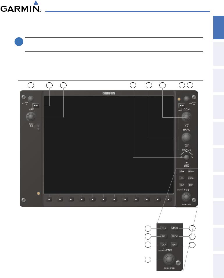
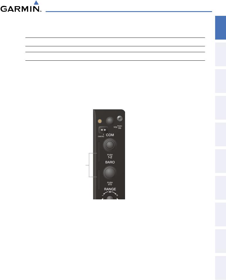
PFD/MFD CONTROLS
1 |
2 |
3 |
4 |
5 |
6 |
7 |
8 |
Figure 1-2 PFD Controls
9 |
13 |
10 |
14 |
11 |
15 |
12 |
|
INDEX APPENDICES ADDITIONALFEATURES AFCS AVOIDANCEHAZARD MANAGEMENTFLIGHT PANELCNSAUDIO& EIS INSTRUMENTSFLIGHT OVERVIEWSYSTEM
190-00749-00 Rev. B |
Garmin G1000 Pilot’s Guide for the Cessna Caravan |
7 |

SYSTEM OVERVIEW
ADDITIONAL HAZARD FLIGHT AUDIO PANEL FLIGHT SYSTEM INDEX APPENDICES FEATURES AFCS AVOIDANCE MANAGEMENT & CNS EIS INSTRUMENTS OVERVIEW
The following list provides an overview of the controls located on the PFD and MFD bezel (see Figure 1-2).
1NAV VOL/ID Knob– Controls NAV audio volume level. Press to toggle the Morse code identifier audio ON and OFF. Volume level is shown in the NAV frequency field as a percentage.
2 NAV Frequency Transfer Key – Toggles the standby and active NAV frequencies.
3Dual NAV Knob – Tunes the standby frequencies for the NAV receiver (large knob for MHz; small knob for kHz). Press to switch the tuning box (cyan box) between NAV1 and NAV2.
4 Joystick – Changes the map range when rotated. Activates the map pointer when pressed.
5 BARO Knob – Sets the altimeter barometric pressure. Press to enter standard pressure (29.92).
6Dual COM Knob – Tunes the standby frequencies for the COM transceiver (large knob for MHz; small knob for kHz). Press to switch the tuning box (cyan box) between COM1 and COM2.
7COM Frequency Transfer Key – Toggles the standby and active COM frequencies. Press and hold this key for two seconds to tune the emergency frequency (121.5 MHz) automatically into the active frequency field.
8COM VOL/SQ Knob – Controls COM audio volume level. Volume level is shown in the COM frequency field as a percentage. Press to turn the COM automatic squelch ON and OFF.
9Direct-to Key ( ) – Allows the user to enter a destination waypoint and establish a direct course to the selected destination (the destination is either specified by the identifier, chosen from the active route, or taken from the map pointer position).
10FPL Key – Displays the active Flight Plan Page for creating and editing the active flight plan.
11CLR Key – Erases information, cancels entries, or removes page menus.
12Dual FMS Knob – Flight Management System Knob. Press the FMS Knob to turn the selection cursor ON and OFF. When the cursor is ON, data may be entered in the applicable window by turning the small and large knobs. The large knob moves the cursor on the page, while the small knob selects individual characters for the highlighted cursor location.
13MENU Key – Displays a context-sensitive list of options. This list allows the user to access additional features or make setting changes that relate to particular pages.
14PROC Key – Gives access to IFR departure procedures (DPs), arrival procedures (STARs) and approach procedures (IAPs) for a flight plan. If a flight plan is used, available procedures for the departure and/or arrival airport are automatically suggested. These procedures can then be loaded into the active flight plan. If a flight plan is not used, both the desired airport and the desired procedure may be selected.
15ENT Key – Validates or confirms a menu selection or data entry.
8 |
Garmin G1000 Pilot’s Guide for the Cessna Caravan |
190-00749-00 Rev. B |
SYSTEM OVERVIEW
AFCS CONTROLS
 NOTE: With the exception of the FD and SPD Keys, if a key is selected, its respective annunciator is illuminated.
1 |
2 |
3 |
4 |
5 |
6 |
7 |
8 |
19 |
18 |
17 |
16 |
15 |
14 |
13 |
12 |
11 |
10 |
9 |
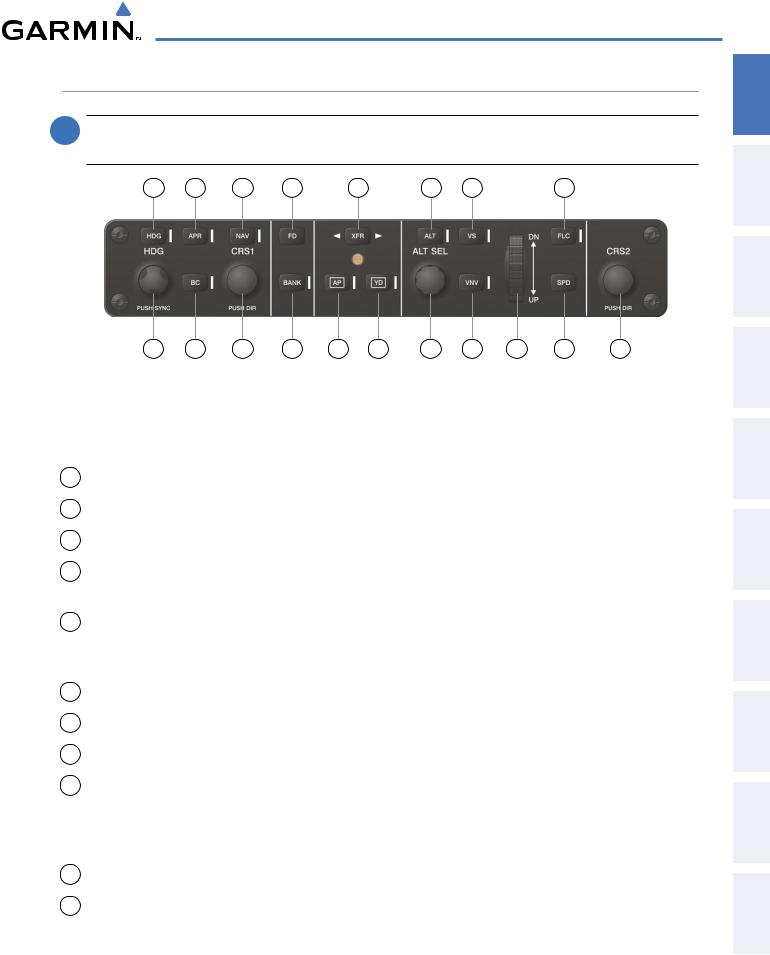
Figure 1-3 AFCS Control Unit (GMC 710)
The GFC 700 AFCS is mainly controlled through the GMC 710 AFCS Control Unit. The AFCS Control Unit consists of the following controls:
1HDG Key – Selects/deselects Heading Select Mode.
2APR Key – Selects/deselects Approach Mode.
3NAV Key – Selects/deselects Navigation Mode.
4FD Key – Activates/deactivates the flight director in the default pitch and roll modes. If the autopilot is engaged, the FD Key is disabled.
5XFRKey– Switchesthe autopilotbetweenthe pilot-sideand thecopilot-sideflightdirectors. Thisselection also selects which air data computer is communicating with the active transponder and which PFD triggers the altitude alert. Upon power-up, the pilot-side FD is selected.
6ALT Key – Selects/deselects Altitude Hold Mode.
7VS Key – Selects/deselects Vertical Speed Mode.
8FLC Key – Selects/deselects Flight Level Change Mode.
9CRS2 Knob – Sets the copilot-selected course on the HSI of PFD2 when the VOR1, VOR2, or OBS/SUSP mode is selected. Pressing this knob centers the CDI on the currently selected VOR. The copilot-selected course provides course reference to the copilot-side flight director when operating in Navigation and Approach modes.
10SPD Key – Disabled on Caravan. If pressed, “SPD NOT AVAIL” is annunciated on the PFD.
11NOSE UP/DN Wheel – Controls the active mode reference for the Pitch, Vertical Speed, and Flight Level Change modes.
INDEX APPENDICES ADDITIONALFEATURES AFCS AVOIDANCEHAZARD MANAGEMENTFLIGHT PANELCNSAUDIO& EIS INSTRUMENTSFLIGHT OVERVIEWSYSTEM
190-00749-00 Rev. B |
Garmin G1000 Pilot’s Guide for the Cessna Caravan |
9 |
SYSTEM OVERVIEW
ADDITIONAL HAZARD FLIGHT AUDIO PANEL FLIGHT SYSTEM INDEX APPENDICES FEATURES AFCS AVOIDANCE MANAGEMENT & CNS EIS INSTRUMENTS OVERVIEW
12VNV Key – Selects/deselects Vertical Navigation mode.
13ALT SEL Knob – Sets the selected altitude in the Selected Altitude Box. In addition to providing the standard G1000 altitude alerter function, selected altitude provides an altitude setting for the Altitude Capture/Hold mode of the AFCS.
14YD Key – Engages/disengages the yaw damper.
15AP Key – Engages/disengages the autopilot.
16BANK Key – Selects/deselects Low Bank Mode.
17CRS1Knob–Setsthepilot-selectedcourseontheHSIofPFD1whentheVOR1,VOR2,orOBS/SUSPmode is selected. Pressing this knob centers the CDI on the currently selected VOR. The pilot-selected course provides course reference to the pilot-side flight director when operating in Navigation and Approach modes.
18BC Key – Selects/deselects Back Course Mode.
19HDG Knob – Sets the selected heading on the HSI. When operating in Heading Select mode, this knob provides the heading reference to the flight director.
ADDITIONAL AFCS CONTROLS
The AP DISC (Autopilot Disconnect) Switch, CWS (Control Wheel Steering) Button, GO AROUND
Switch, and MEPT (Manual Electric Pitch Trim) Switch are additional AFCS controls and are located in the cockpit, separately from the AFCS Control Unit. These are discussed in detail in the AFCS section.
10 |
Garmin G1000 Pilot’s Guide for the Cessna Caravan |
190-00749-00 Rev. B |
SYSTEM OVERVIEW
AUDIO PANEL CONTROLS
1 |
2 |
3 |
4 |
5 |
6 |
7 |
8 |
9 |
10 |
11 |
12 |
13 |
14 |
15 |
16 |
17 |
|
18 |
19 |
20 |
21 |
22 |
23 |
|
24 |
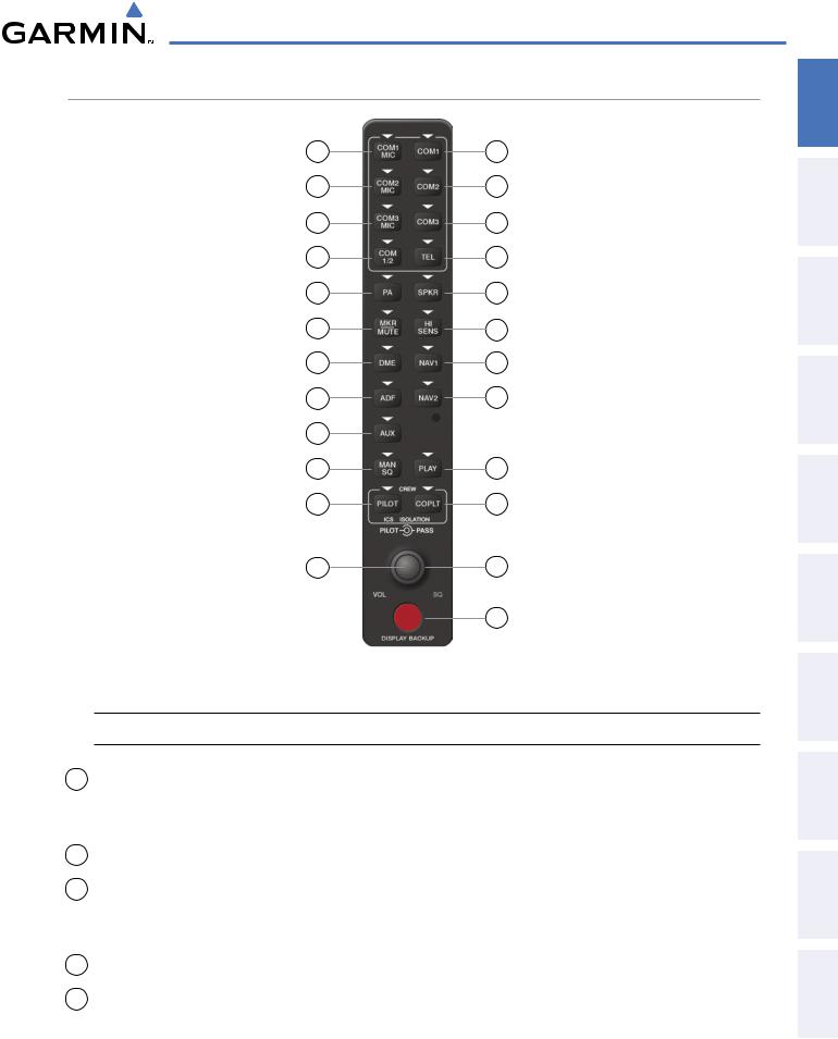
Figure 1-4 Audio Panel Controls (GMA 1347)
 NOTE: When a key is selected, a triangular annunciator above the key is illuminated.
1COM1 MIC – Selects the #1 transmitter for transmitting. COM1 is simultaneously selected when this key is pressed allowing received audio from the #1 COM receiver to be heard. COM2 receiver audio can be added by pressing the COM2 Key.
2COM1 – When selected, audio from the #1 COM receiver can be heard.
3COM2 MIC – Selects the #2 transmitter for transmitting. COM2 is simultaneously selected when this key is pressed allowing received audio from the #2 COM receiver to be heard. COM2 can be deselected by pressing the COM2 Key, or COM1 can be added by pressing the COM1 Key.
4COM2 – When selected, audio from the #2 COM receiver can be heard.
5COM3 MIC – Not used on Cessna Caravan aircraft.
INDEX APPENDICES ADDITIONALFEATURES AFCS AVOIDANCEHAZARD MANAGEMENTFLIGHT PANELCNSAUDIO& EIS INSTRUMENTSFLIGHT OVERVIEWSYSTEM
190-00749-00 Rev. B |
Garmin G1000 Pilot’s Guide for the Cessna Caravan |
11 |

ADDITIONAL HAZARD FLIGHT AUDIO PANEL FLIGHT SYSTEM INDEX APPENDICES FEATURES AFCS AVOIDANCE MANAGEMENT & CNS EIS INSTRUMENTS OVERVIEW
SYSTEM OVERVIEW
6COM3 – Not used on Cessna Caravan aircraft.
7COM 1/2 – Split COM is disabled on Cessna Caravan aircraft.
8TEL – Pressing this key selects and de-selects the airborne telephone.
9PA – Selects the passenger address system. The selected Com transmitter is deselected when the PA Key is pressed.
10SPKR – Pressing this key selects and deselects the corresponding cockpit speaker. COM and NAV receiver audio will be heard on the speaker.
11MKR/MUTE – Mutes the currently received marker beacon receiver audio. Unmutes when new marker beacon audio is received. Also, stops play of the clearance recorder.
12HI SENS – Press to increase marker beacon receiver sensitivity. Press again to return to normal.
13DME – Pressing turns DME audio on or off.
14NAV1 – When selected, audio from the #1 NAV receiver can be heard.
15ADF – Pressing turns on or off the audio from the ADF receiver.
16NAV2 – When selected, audio from the #2 NAV receiver can be heard.
17AUX – Not used on Cessna Caravan aircraft.
18MAN SQ – Press to enable manual squelch for the intercom. When active, press the PILOT Knob to illuminate ‘SQ’. Turn the PILOT/PASS Knobs to adjust squelch.
19PLAY – Press once to play the last recorded audio. Pressing the PLAY Key during play begins playing the previously recorded memory block. Each subsequent press of the PLAY Key will begin playing the next previously recorded block. Press the MKR/MUTE Key to stop play.
20PILOT – Pressing selects the pilot intercom isolation. Press again to deselect pilot isolation.
21COPLT – Pressing selects the copilot intercom isolation. Press again to deselect copilot isolation.
22PILOT Knob – Press to switch between volume and squelch control as indicated by the ‘VOL’ or ‘SQ’ being illuminated. Turn to adjust intercom volume or squelch. The MAN SQ Key must be selected to allow squelch adjustment.
23PASS Knob – Turn to adjust Copilot/Passenger intercom volume or squelch. The MAN SQ Key must be selected to allow squelch adjustment.
24Reversionary Mode (Display Backup) Button – Pressing manually selects Reversionary Mode.
12 |
Garmin G1000 Pilot’s Guide for the Cessna Caravan |
190-00749-00 Rev. B |
SYSTEM OVERVIEW
1.4 SECURE DIGITAL CARDS
 NOTE: Ensure the G1000 System is powered off before inserting an SD card.
 NOTE: Refer to Appendix B for instructions on updating databases.
The PFD and MFD data card slots use Secure Digital (SD) cards and are located on the upper right side of the display bezels. Each display bezel is equipped with two SD card slots. SD cards are used for aviation database and system software updates as well as terrain database storage.
Installing an SD card:
1)Insert the SD card in the SD card slot (the front of the card should be flush with the face of the display bezel).
2)To eject the card, gently press on the SD card to release the spring latch.
SD Card Slots
Figure 1-5 Display Bezel SD Card Slots
INDEX APPENDICES ADDITIONALFEATURES AFCS AVOIDANCEHAZARD MANAGEMENTFLIGHT PANELCNSAUDIO& EIS INSTRUMENTSFLIGHT OVERVIEWSYSTEM
190-00749-00 Rev. B |
Garmin G1000 Pilot’s Guide for the Cessna Caravan |
13 |
ADDITIONAL HAZARD FLIGHT AUDIO PANEL FLIGHT SYSTEM INDEX APPENDICES FEATURES AFCS AVOIDANCE MANAGEMENT & CNS EIS INSTRUMENTS OVERVIEW
SYSTEM OVERVIEW
1.5 SYSTEM POWER-UP
 NOTE: Refer to the Appendices for AHRS initialization bank angle limitations.
 NOTE: See the Appendices for additional information regarding system-specific annunciations and alerts.
 NOTE: See the Pilot’s Operating Handbook (POHAFM) for specific procedures concerning avionics power application and emergency power supply operation.
The G1000 system is integrated with the aircraft electrical system and receives power directly from electrical busses. The G1000 PFDs, MFD and supporting sub-systems include both power-on and continuous built-in test features that exercise the processor, RAM, ROM, external inputs and outputs to provide safe operation.
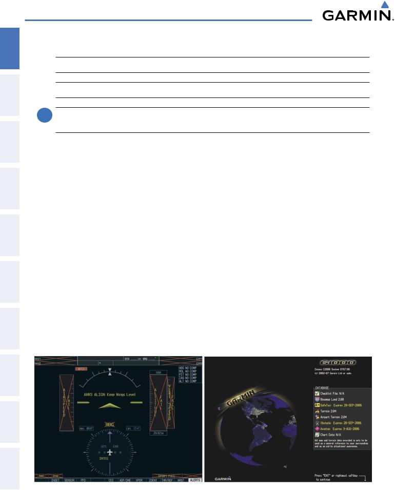
During system initialization, test annunciations are displayed, as shown in Figure 1-7. All system annunciations should disappear typically within one minute of power-up. Upon power-up, key annunciator lights also become momentarily illuminated on the audio panels, the control units and the display bezels.
On the PFD, the AHRS begins to initialize and displays ‘AHRS ALIGN: Keep Wings Level’. The AHRS should display valid attitude and heading fields typically within one minute of power-up. The AHRS can align itself both while taxiing and during level flight.
When the MFD powers up (Figure 1-8), the MFD Power-up Page displays the following information:
• System version |
• Terrain database name and version |
• Copyright |
• Aviation database name, version, and effective dates |
• Land database name and version |
• Chartview database information |
• Obstacle database name and version |
• Safe Taxi database information |
Current database information includes the valid operating dates, cycle number and database type. When this information has been reviewed for currency (to ensure that no databases have expired), the pilot is prompted to continue. Pressing the ENT Key acknowledges this information and displays the (MAP) Navigation Map Page.
Figure 1-7 PFD Initialization |
Figure 1-8 MFD Power-up Page |
14 |
Garmin G1000 Pilot’s Guide for the Cessna Caravan |
190-00749-00 Rev. B |
SYSTEM OVERVIEW
1.6 SYSTEM OPERATION
The displays are connected together via a single Ethernet bus, thus allowing for high-speed communication. This section discusses the normal and reversionary modes of operation as well as the various AHRS modes of the G1000 system.
In the event of display failure, the display modes are as follows:
•PFD1 failure – MFD enters reversionary mode.
•MFD failure – PFD1 and PFD 2 enter reversionary mode.
•PFD2 failure – No reversionary mode available. PFD 1 and the MFD function normally.
EIS FLIGHT SYSTEM INSTRUMENTS OVERVIEW
NORMAL OPERATION
PFD
In normal mode, the PFD presents graphical flight instrumentation (attitude, heading, airspeed, altitude and vertical speed), thereby replacing the traditional flight instrument cluster. The PFD also offers control for COM and NAV frequency selection.
MFD
Innormalmode,therightportionoftheMFDdisplaysafull-colormovingmapwithnavigationinformation, while the left portion of the MFD is dedicated to the Engine Indication System (EIS).
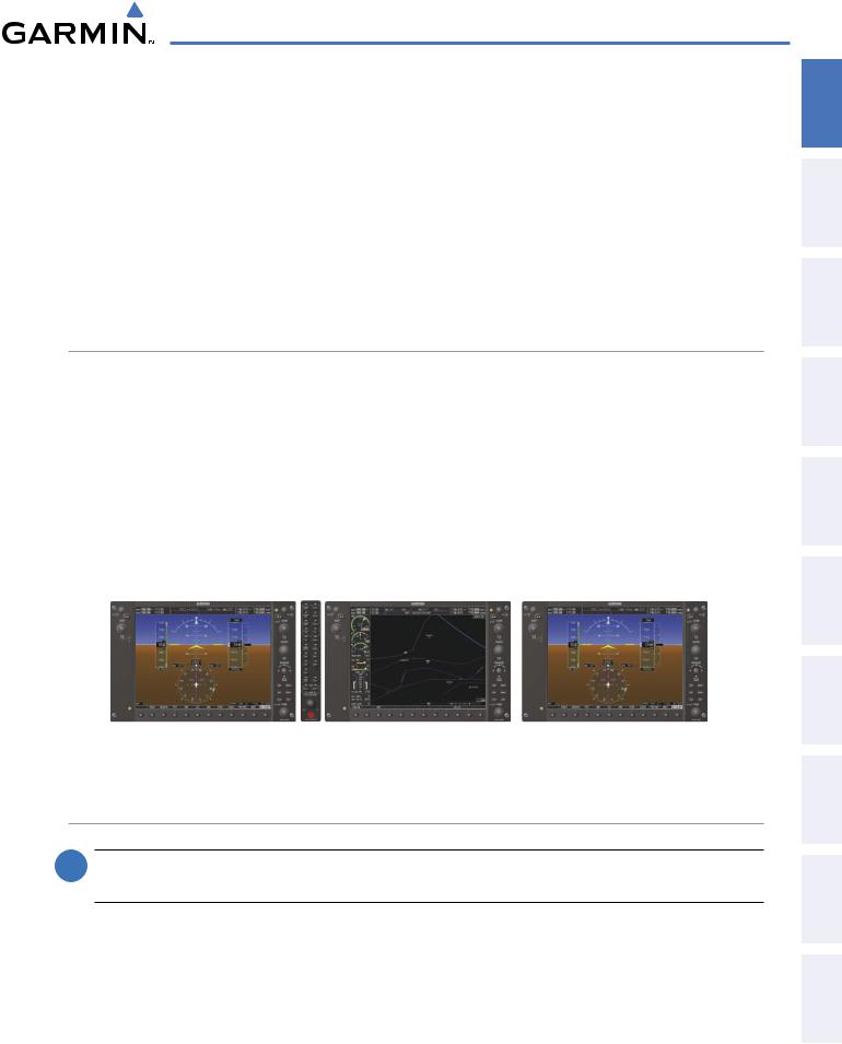
Figure 1-9 gives an example of the G1000 displays in normal mode.
PFD1 |
MFD |
PFD2 |
Figure 1-9 Normal Operation
REVERSIONARY MODE
 NOTE:TheG1000systemalertsthepilotwhenbackuppathsareutilizedbytheLRUs. RefertotheAppendices
for further information regarding system-specific alerts.
In the event of PFD1 or MFD failure, reversionary (or backup) mode is selected by pressing the red Display Backup Button on the Audio Panel. Reversionary mode is a mode of operation in which all important flight information is presented on at least one of the remaining displays (see Figure 1-10). Transition to reversionary mode should be straightforward for the pilot, for flight parameters are presented in the same format as in normal mode.
INDEX APPENDICES ADDITIONALFEATURES AFCS AVOIDANCEHAZARD MANAGEMENTFLIGHT PANELCNSAUDIO&
190-00749-00 Rev. B |
Garmin G1000 Pilot’s Guide for the Cessna Caravan |
15 |

SYSTEM OVERVIEW
HAZARD FLIGHT AUDIO PANEL FLIGHT SYSTEM AFCS AVOIDANCE MANAGEMENT & CNS EIS INSTRUMENTS OVERVIEW
Figure 1-10 Reversionary Mode
Pressing the DISPLAY BACKUP button activates/ deactivates reversionary mode for both the on-side PFD and the MFD.
Figure 1-11 DISPLAY BACKUP Button
Each display can be configured to operate in reversionary mode, as follows:
•PFD1 – By pressing the DISPLAY BACKUP button on the audio panel.
•MFD – By pressing the DISPLAY BACKUP button on the audio panel.
•PFD2 – By pressing the DISPLAY BACKUP button on the audio panel.
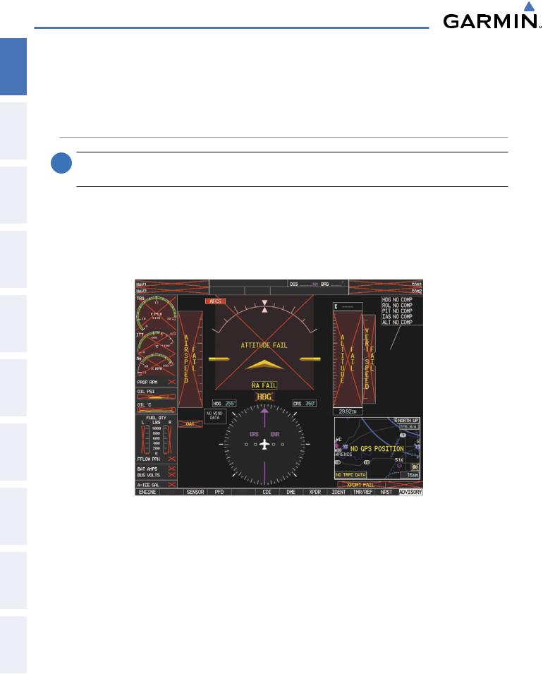
Should the connection between PFD1 and GIA #1 or the MFD and GIA #2 become inoperative, the associated GIA 63W can no longer communicate with the remaining display(s) (refer to Figure 1-1). As a result, the NAV and COM functions provided to the failed display(s) by the associated GIA 63W are flagged (red “X”) as invalid (see Figure 1-12).
ADDITIONAL INDEX APPENDICES FEATURES
Figure 1-12 Inoperative Input (NAV1 Shown)
AHRS OPERATION
 NOTE: Refer to the Appendices for specific AHRS alert information.
NOTE: Aggressive maneuvering in any of the three reversionary modes listed inTable 1-1 can degradeAHRS accuracy.
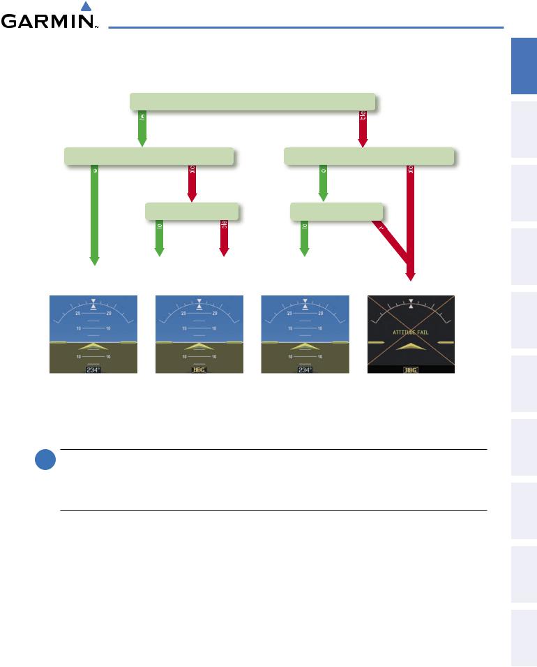
In addition to using internal sensors, the GRS 77 AHRS uses GPS information, magnetic field data and air data to assist in attitude/heading calculations. In normal mode, the AHRS relies upon GPS and magnetic field measurements. If either of these external measurements is unavailable or invalid, the AHRS uses air data information for attitude determination. Four AHRS modes of operation are available (see Figure 1-13)
16 |
Garmin G1000 Pilot’s Guide for the Cessna Caravan |
190-00749-00 Rev. B |
SYSTEM OVERVIEW
and depend upon the combination of available sensor inputs. Loss of air data, GPS, or magnetometer sensor inputs is communicated to the pilot by message advisory alerts.
GPS Data
|
availab |
|
|
Magnetometer Data |
|||
availab |
|
unavailab |
|
|
Air Data |
||
|
availab |
unavailab |
|
AHRS Normal |
AHRS noAHRS no-Mag/ |
||
Mag Mode |
no-Air Mode |
||
Operation |
|||
Heading Invalid |
|||
|
|||
|
unavailab |
Magnetometer Data |
|
availab |
unavailab |
Air Data |
|
availab |
una |
v |
|
|
ailab |
|
le |
AHRS |
|
no-GPS |
Attitude/Heading Invalid |
Mode |
|
Figure 1-13 AHRS Operation
GPS INPUT FAILURE
 NOTE: In-flight initialization of AHRS, when operating without any valid source of GPS data and at true air speed values greater than approximately 175 knots, is not guaranteed. Under these rare conditions, it is possible for in-flight AHRS initialization to take an indefinite amount of time which would result in an extended period of time where valid AHRS outputs are unavailable.
The G1000 system provides two sources of GPS information. If a single GPS receiver fails, or if the information provided from one of the GPS receivers is unreliable, the AHRS seamlessly transitions to using the other GPS receiver. An alert message informs the pilot of the use of the backup GPS path. If both GPS inputs fail, the AHRS continues to operate in reversionary No-GPS mode so long as the air data and magnetometer inputs are available and valid.
AIR DATA INPUT FAILURE
A failure of the air data input has no effect on AHRS output while AHRS is operating in normal mode. A failure of the air data input while the AHRS is operating in reversionary No-GPS mode results in invalid attitude and heading information on the PFD (as indicated by red “X” flags).
INDEX APPENDICES ADDITIONALFEATURES AFCS AVOIDANCEHAZARD MANAGEMENTFLIGHT PANELCNSAUDIO& EIS INSTRUMENTSFLIGHT OVERVIEWSYSTEM
190-00749-00 Rev. B |
Garmin G1000 Pilot’s Guide for the Cessna Caravan |
17 |
ADDITIONAL HAZARD FLIGHT AUDIO PANEL FLIGHT SYSTEM INDEX APPENDICES FEATURES AFCS AVOIDANCE MANAGEMENT & CNS EIS INSTRUMENTS OVERVIEW
SYSTEM OVERVIEW
MAGNETOMETER FAILURE
If the magnetometer input fails, the AHRS transitions to one of the reversionary No-Magnetometer modes and continues to output valid attitude information. However, if the aircraft is airborne, the heading output on the PFD does become invalid (as indicated by a red “X”).
G1000 SYSTEM ANNUNCIATIONS
 NOTE: For a detailed description of all annunciations and alerts, refer to Appendix A. Refer to the Airplane Flight Manual (AFM) for additional information regarding pilot responses to these annunciations.
When an LRU or an LRU function fails, a large red “X” is typically displayed on windows associated with the failed data (Figure 1-14 displays all possible flags and responsible LRUs). Upon G1000 power-up, certain windows remain invalid as equipment begins to initialize. All windows should be operational within one minute of power-up. If any window remains flagged, the G1000 system should be serviced by a Garminauthorized repair facility.
GIA 63W |
|
GIA 63W |
|||||||||||||||||||||||
Integrated |
|
|
|
|
|
|
|
|
|
|
|
|
|
|
Integrated |
||||||||||
|
|
|
|
|
|
|
|||||||||||||||||||
Avionics Units |
|
Avionics Units |
|||||||||||||||||||||||
|
|
|
|
|
|
|
|
|
|
|
|
|
|
|
|
|
|
|
|
|
|
|
|
|
GDC 74A Air |
GEA 71 Engine |
|
|
|
|
|
|
|
|
|
|
|
|
|
|
|
|
|
|
|
|
|
Data Computer |
|||
|
|
|
|
|
|
|
|
|
|
|
|
|
|
|
|
|
|
|
|
||||||
|
|
|
|
|
|
|
|
|
|
||||||||||||||||
Airframe Unit |
|
|
|
|
|
|
|
|
|
|
|
|
|||||||||||||
OR |
|
|
|
|
|
|
|
|
|
|
|
|
|
|
GRS 77 AHRS |
||||||||||
|
|
||||||||||||||||||||||||
GIA 63W |
|
|
|
|
|
|
|
|
|
|
|
|
|
|
|
|
|
|
|
|
|
||||
|
|
|
|
|
|
|
|
|
|
|
|
|
|
|
|
|
OR |
||||||||
Integrated |
|
|
|
|
|
|
|
|
|
|
|
|
|
|
|
|
|
|
|
|
|
||||
|
|
|
|
|
|
|
|
|
|
|
|
|
|
|
GMU 44 |
||||||||||
|
|
|
|
|
|
|
|
|
|
|
|
|
|
||||||||||||
Avionics Unit |
|
|
|
|
|
|
|
|
|
|
|
|
|
|
|
|
|
|
|
|
|
||||
|
|
|
|
|
|
|
|
|
|
|
|
|
|
|
Magnetometer |
||||||||||
|
|
|
|
|
|
|
|
|
|
|
|
|
|
|
|
|
|
|
|
|
|
|
|
|
|
|
|
|
|
|
|
|
|
|
|
|
|
|
|
|
|
|
|
|
|
|
GIA 63W |
||||
|
|
|
|
|
|
|
|
|
|
|
|
|
|
|
|
|
|
|
|
||||||
Fuel Quantity |
|
|
|
|
|
|
|
|
|
|
|
|
|||||||||||||
|
|||||||||||||||||||||||||
Signal |
|
|
|
|
|
|
|
|
|
|
|
|
|
|
|
Integrated |
|||||||||
Conditioner |
|
|
|
|
|
|
|
|
|
|
|
Avionics Units |
|||||||||||||
GEA 71 Engine |
|
|
|
|
|
|
|
|
|
|
|
|
|
|
|
|
|
GTX 33/D |
|||||||
|
|
|
|
|
|
|
|
|
|
|
|
|
|
|
|||||||||||
Airframe Unit |
|
|
|
|
|
|
|
|
|
|
|
|
|
Transponder |
|||||||||||
|
|
|
|
|
|
|
|
|
|
|
|
|
|
|
|
|
|
|
|
|
|||||
|
|
|
|
|
|
|
|
|
|
|
|
|
|
|
|
|
|
|
|
|
|
|
|
|
OR |
GDC 74A Air |
|
|
|
|
|
|
|
|
|
|
|
|
|
||||||||||||
|
|
|
|
|
|
|
|
|
|
|
GIA 63W |
||||||||||||||
Data Computer |
|
|
|
|
|
|
|
|
|
|
|
|
Integrated |
||||||||||||
|
|
|
|
|
|
|
|
Figure 1-14 G1000 System Failure Annunciations |
|
Avionics Units |
|||||||||||||||
18 |
Garmin G1000 Pilot’s Guide for the Cessna Caravan |
190-00749-00 Rev. B |
SYSTEM OVERVIEW
SOFTKEY FUNCTION
The softkeys are located along the bottoms of the displays. The softkeys shown depend on the softkey level or page being displayed. The bezel keys below the softkeys can be used to select the appropriate softkey. When a softkey is selected, its color changes to black text on gray background and remains this way until it is turned off, at which time it reverts to white text on black background.
In the following descriptions, top level softkeys are denoted by bullets.
Softkey |
Bezel-Mounted |
Softkey Names |
On |
Softkeys (press) |
(displayed) |
EIS FLIGHT SYSTEM INSTRUMENTS OVERVIEW
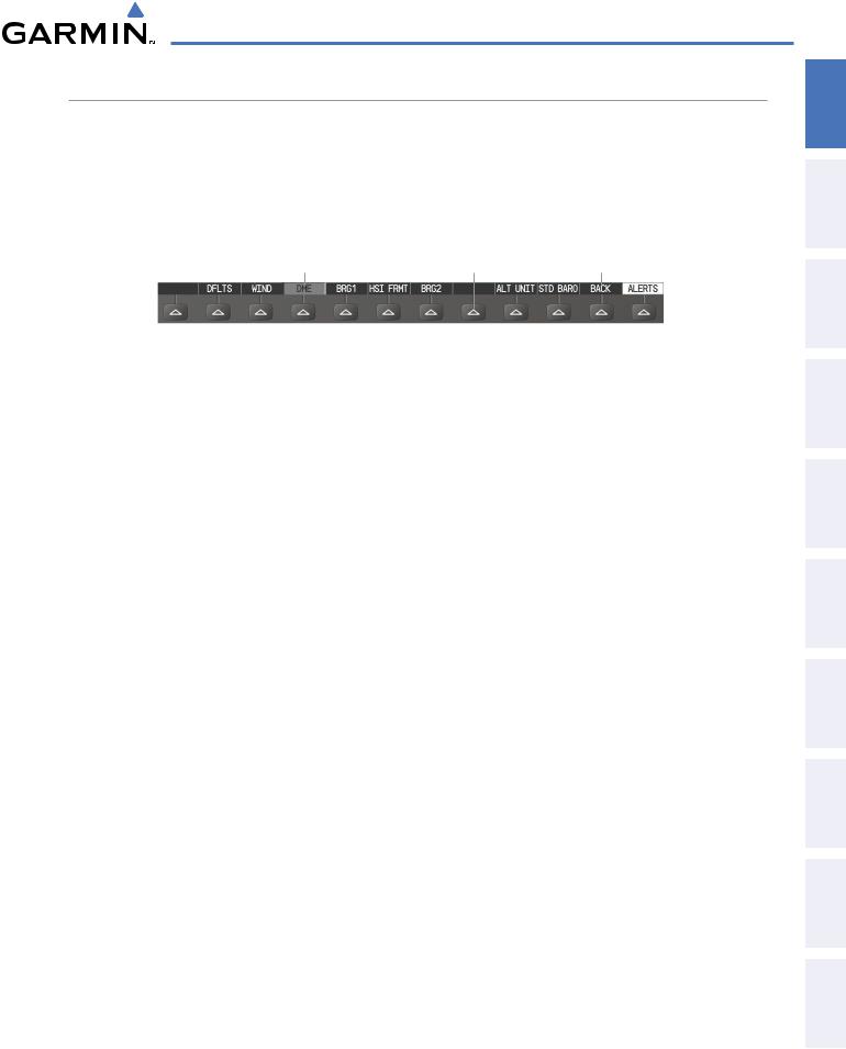
Figure 1-15 Softkeys (Second-Level PFD Configuration)
PFD SOFTKEYS
The CDI, IDENT, TMR/REF, NRST, and ALERTS Softkeys undergo a momentary change to black text on gray background and automatically switch back to white text on black background when selected. If alerts remain after acknowledgement, the ALERTS Softkey will be black on white.
The PFD softkeys provide control over flight management functions, including GPS, NAV, terrain, traffic, and lightning (optional). Each softkey sublevel has a BACK Softkey which can be pressed to return to the previous level. The ALERTS Softkey is visible in all softkey levels. For the top level softkeys and the transponder (XPDR) levels, the IDENT Softkey remains visible.
INSET |
Displays Inset Map in PFD lower left corner |
OFF |
Removes Inset Map |
DCLTR (3) |
Selects desired amount of map detail; cycles through declutter levels: |
|
DCLTR (No Declutter): All map features visible |
|
DCLTR-1: Declutters land data |
|
DCLTR-2: Declutters land and SUA data |
|
DCLTR-3: Removes everything except for the active flight |
|
plan |
TRAFFIC |
Displays traffic information on Inset Map |
TOPO |
Displays topographical data (e.g., coastlines, terrain, rivers, lakes) |
|
and elevation scale on Inset Map |
TERRAIN |
Displays terrain information on Inset Map |
STRMSCP |
Displays Stormscope information on Inset Map (optional feature) |
NEXRAD |
Displays NEXRAD weather and coverage information on Inset Map |
|
(optional feature) |
XM LTNG |
Displays XM lightning information on Inset Map (optional feature) |
INDEX APPENDICES ADDITIONALFEATURES AFCS AVOIDANCEHAZARD MANAGEMENTFLIGHT PANELCNSAUDIO&
190-00749-00 Rev. B |
Garmin G1000 Pilot’s Guide for the Cessna Caravan |
19 |
Loading...