


UPS Aviation Technologies, Inc.
2345 Turner Road, SE
Salem, OR 97302
www.upsat.com
560-0975-03 December 2001
16 |
SL15-Series Pilot Guide |
No part of this document may be reproduced in any form or by any means without the express written consent of UPS Aviation Technologies, Inc. UPS Aviation Technologies, Inc., II Morrow, and Apollo are trademarks of UPS Aviation Technologies, Inc.
© 2001 by UPS Aviation Technologies, Inc. All rights reserved. Printed in the U.S.A.
UPS Aviation Technologies, Inc.
2345 Turner Road, S.E. Salem, OR 97302
U.S.A. Toll Free |
800.525.6726 |
Canada Toll Free |
800.654.3415 |
International |
503.391.3411 |
FAX |
503.364.2138 |
Visit our web page at http://www.upsat.com
Send comments about this manual by email to: techpubs@at.ups.com
History of Revisions |
|
|
Original Release |
July 1999 |
Rev. - |
|
July 2000 |
Rev. -01 |
|
January 2001 |
Rev. -02 |
|
December 2001 |
Rev. -03 |
Ordering Information
To receive additional copies of the Apollo SL15 User’s Guide, order part #560-0975-03.
Patent No. 5,903,277 & 6,160,496
FAA-Approved TSO C50c, C35d
JAA-Approved JTSO-2C35d, C50c
2 |
SL15-Series Pilot Guide |
SL15-Series Pilot Guide |
15 |
Notes |
OPERATION |
|
|
|
GENERAL INFORMATION |
1SCOPE
This section provides detailed operating instructions for the UPS Aviation Technologies SL15 Audio Selector Panel/Intercom System. Please read it carefully before using the equipment so that you can take full advantage of its capabilities.
This section is divided into four sections covering the basic operating areas of the SL15 systems. They are Audio Selector, Transceiver Selection, Intercom, and Marker Beacon Receiver.
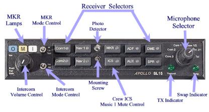
SL15 controls
2Power Switch (EMG-Fail Safe Operation)
Unit power is turned on and off by pushing the volume knob. In the OFF or "EMG" position, the pilot is connected directly to Com 1. This allows communication capability regardless of unit condition. Any time power is removed or turned OFF, the audio selector will be placed in the fail-safe mode.
The power switch also controls the audio selector panel functions, intercom, and marker beacon receiver. Unless the mic selector is in Com 3 mode, at least one of the selected audio LEDs will be on (Com 1 or Com 2).
3Microphone Selector (All models)
14 |
SL15-Series Pilot Guide |
SL15-Series Pilot Guide |
3 |
 Loading...