


WF-7720
Table of contents
 Loading...
SERVICE MANUAL
Color Inkjet Printer
Epson WF-7720 Series
Epson WF-7710 Series
Epson WF-7210 Series
CONFIDENTIAL
SEMF17-007

Notice:
All rights reserved. No part of this manual may be reproduced, stored in a retrieval system, or transmitted in any form or
by any means, electronic, mechanical, photocopying, recording, or otherwise, without the prior written permission of
SEIKO EPSON CORPORATION.
All effort have been made to ensure the accuracy of the contents of this manual. However, should any errors be
detected, SEIKO EPSON would greatly appreciate being informed of them.
The contents of this manual are subject to change without notice.
The above not withstanding SEIKO EPSON CORPORATION can assume no responsibility for any errors in this
manual or the consequences thereof.
EPSON is a registered trademark of SEIKO EPSON CORPORATION.
Note :Other product names used herein are for identification purpose only and may be trademarks or r egistered
trademarks of their respective owners. EPSON disclaims any and all rights in those marks.
Copyright 2017 SEIKO EPSON CORPORATION
P・CS Quality Assurance Department
Confidential

Safety Precautions
All safety procedures described here shall be strictly adhered to by all parties servicing and maintaining this
product.
DANGER
Strictly observe the following cautions. Failure to comply could result in serious bodily injury or loss of life.
1. Always disconnect the product from the power source and peripheral devices when servicing the product or
performing maintenance.
2. When performing works described in this manual, do not connect to a power source until instructed to do so.
Connecting to a power source causes high voltage in the power supply unit and some electronic components
even if the product power switch is off. If you need to perform the work with the power cable connected to a
power source, use extreme caution to avoid electrical shock.
WARNING
Strictly observe the following cautions. Failure to comply may lead to personal injury or loss of life.
1. Always wear protective goggles for disassembly and reassembly to protect your eyes from ink in working. If
any ink gets in your eyes, wash your eyes with clean water and consult a doctor immediately.
2. When using compressed air products; such as air duster, fo r cleaning during repair and maintenance, the use
of such products containing flammable gas is prohibited.
PRECAUTIONS
Strictly observe the following cautions. Failure to comply may lead to personal injury or damage of the product.
1. Repairs on Epson product should be performed only by an Epson certified repair technician.
2. No work should be performed on this product by persons unfamiliar with basic safety knowledge required for
electrician.
3. The power rating of this product is indicated on the serial number/rating plate. Never connect this product to
the power source whose voltages is different from the rated voltage.
4. Replace malfunctioning components only with those components provided or approved by Epson;
introduction of second-source ICs or other non-approved components may damage the product and void any
applicable Epson warranty.
5. The capacitors on the Main Board may be electrically charged right after the power turns off or after driving
motors which generates counter electromotive force such as when rotating the PF Roller or when moving the
CR Unit. There is a risk to damage the Main Board if the Head FFC is short-circuited with the capacitors on
the Main Board electrically charged, therefore, after the power turns off or after motors are driven, leave the
printer untouched for approximately 30 seconds to discharge the capacitors before starting disassembly/
reassembly.
6. To prevent the circuit boards from short-circuiting, be careful about the following when handling FFC or
cables.
When handling FFC, take care not to let the terminal section of FFC touch metal parts.
When connecting cables/FFC to the connectors on circuit boards, connect them straight to the connectors to avoid
slant insertion.
Confidential

7. In order to protect sensitive microprocessors and circuitry, use static discharge equipment, such as anti-static
wrist straps, when accessing internal components.
8. Do not tilt this product immediately after initial ink charge, especially after performing the ink charge several
times. Doing so may cause ink to leak from the product because it may take some time for the waste ink pads
to completely absorb ink wasted due to the ink charge.
9. Never touch the ink or wasted ink with bare hands. If ink comes into contact with your skin, wash it off with
soap and water immediately. If you have a skin irritation, consult a doctor immediately.
10. When disassembling or assembling this product, make sure to wear gloves to avoid injuries from metal parts
with sharp edges.
11. Use only recommended tools for disassembling, assembling or adjusting the printer.
12. Observe the specified torque when tightening screws.
13. Be extremely careful not to scratch or contaminate the following parts.
Nozzle plate of the printhead
CR Scale
PF Scale
Coated surface of the PF Roller
Gears
Rollers
LCD
Scanner Sensor
Exterior parts
14. Never use oil or grease other than those specified in this manual. Use of different types of oil or grease may
damage the component or give bad influence on the printer function.
15. Apply the specified amount of grease described in this manua l .
16. Make the specified adjustments when you disassemble the printer.
17. When cleaning this product, follow the procedure described in this manual.
18. When transporting this product after filling the ink in the printhead, pack the printer without removing the
ink cartridges in order to prevent the printhead from drying out.
19. Make sure to install antivirus software in the computers used for the service support activities.
20. Keep the virus pattern file of antivirus software up-to-date.
21. When disassembling/reassembling this product, if you find adhesive power of the double-sided tape which
secure the parts or FFC is not enough, replace the tape with new one and attach it correctly to the specified
points where the parts or FFC should be secured.
22. Unless otherwise specified in this manual, the labels attached on the returned product should be transferred to
the corresponding attachment positions on the new one referring to the labels on the returned product.
Confidential

About This Manual
This manual, consists of the following chapters, is intended for repair service personnel and includes information
necessary for properly performing maintenance and servicing the product.
CHAPTER 1. TROUBLESHOOTING
Describes the step-by-step procedures for the troubleshooting.
CHAPTER 2. DISASSEMBLY / REASSEMBLY
Describes the disassembly/reassembly procedures for main parts/units of the product, and provides the
standard operation time for servicing the product.
CHAPTER 3. ADJUSTMENT
Describes the required adjustments for servicing the product.
CHAPTER 4. MAINTENANCE
Describes maintenance items and procedures for servicing the product.
CHAPTER 5. APPENDIX
Provides the following additional information for reference:
Connector Diagram
Protection for Transportation
Symbols Used in this Manual
Various symbols are used throughout this manual either to provide additional information on a specific topic or
to warn of possible danger present during a procedure or an action. Pay attention to all symbols when they are
used, and always read explanation thoroughly and follow the instructions.
Indicates an operating or maintenance procedure, practice or condition that, if not strictly observed,
could result in serious injury or loss of life.
Indicates an operating or maintenance procedure, practice, or condition that, if not strictly observed,
could result in bodily injury, damage or malfunction of equipment.
May indicate an operating or maintenance procedure, practice or condition that is necessary to
accomplish a task efficiently. It may also provide additional information that is related to a specific
subject, or comment on the results achieved through a previous action.
For Chapter 2 “Disassembly/Reassembly”, symbols other than indicated above are used to show additional
information for disassembly/reassembly. For the details on those symbols, see "2.2 Disassembly/Reassembly
Procedures (p46)".
Confidential

Revision Status
Revision Date of Issue Description
A Sep. 12, 2017 First Release
B Nov. 22, 2017 Revise the Contents
Made Change the Enter ID to Service Support Mode in " 1.4 Service Support Mode (p29)"
Confidential

Epson WF-7720 / WF-7710 / WF-7210 Series Revision A
Contents
Chapter 1 Troubleshooting
1.1 Troubleshooting....................................................................................................................................................... 10
1.1.1 Troubleshooting Workflow ............................................................................................................................ 10
1.2 Power-On Sequence ................................................................................................................................................ 13
1.3 Fatal Error Code List............................................................................................................................................... 15
1.3.1 D isplaying the Fatal Error Code..................................................................................................................... 15
1.3.2 Fatal Error Code ............................................................................................................................................. 16
1.3.2.1 ADF/Scanner ................................................................... 16
1.3.2.2 Printer (CR)..................................................................... 21
1.3.2.3 Printer (PF) ..................................................................... 23
1.3.2.4 Printer (ASF).................................................................... 25
1.3.2.5 Printer (PE/Head/CSIC) ........................................................... 26
1.3.2.6 Printer (others) .................................................................. 27
1.3.2.7 System Error .................................................................... 28
1.4 Service Support Mode ............................................................................................................................................. 29
1.4.1 Status Sheet Information ................................................................................................................................ 31
Chapter 2 Disassembly/Reassembly
2.1 O verview ................................................................................................................................................................. 41
2.1.1 Tools ............................................................................................................................................................... 41
2.1.2 Jigs .................................................................................................................................................................. 41
2.1.3 Standard Operation Time for servicing the product ....................................................................................... 42
2.2 D isassembly/Reassembly Procedures ..................................................................................................................... 46
2.2.1 Functional differences between models and component parts....................................................................... 46
2.2.2 Functional differences between models and component parts....................................................................... 48
2.2.3 Disassembly Flowchart................................................................................................................................... 49
2.2.3.1 Housing Part (WF-7720/WF-7710 Series) ............................................................................................ 50
2.2.3.2 Housing Part (WF-7210 Series)............................................................................................................. 51
2.2.3.3 Printer Mechanism Part ......................................................................................................................... 52
2.3 Detailed Disassembly/Reassembly Procedure for each Part/Unit........................................................................... 57
2.4 Routing FFCs/cables ............................................................................................................................................... 66
Chapter 3 Adjustment
3.1 Required Adjustments ............................................................................................................................................. 72
3.2 D etails of Adjustments ............................................................................................................................................ 81
3.2.1 PF/CR Timing Belt Tension Measurement .................................................................................................... 81
3.2.1.1 PF Timing Belt Tension Measurement.................................................................................................. 82
3.2.1.2 CR Timing Belt Tension Check............................................................................................................. 83
3.2.2 PG Adjustment ............................................................................................................................................... 84
3.2.2.1 PG Adjustment procedure...................................................................................................................... 84
3.2.2.2 Preparation ............................................................................................................................................. 85
3.2.2.3 PG adjustment procedure....................................................................................................................... 88
3.2.2.4 Checking the Platen Gap........................................................................................................................ 90
Chapter 4 Maintenance
4.1 Cleaning................................................................................................................................................................... 92
4.1.1 Cleaning the CR Unit ..................................................................................................................................... 92
4.1.2 Cleaning the Exterior Parts/inside of the printer ............................................................................................ 93
4.2 Lubrication .............................................................................................................................................................. 94
7
Confidential

Epson WF-7720 / WF-7710 / WF-7210 Series Revision A
4.3 Lubrication Points and Instructions......................................................................................... ................................ 95
Chapter 5 Appendix
5.1 Connector Diagram ................................................................................................................................................. 99
5.2 P rotection for Transportation ................................................................................................................................ 100
5.2.1 Securing the CR Unit.................................................... ... ..................................... ........................................ 100
8
Confidential

CHAPTER 1
TROUBLESHOOTING
Confidential
Epson WF-7720 / WF-7710 / WF-7210 Series
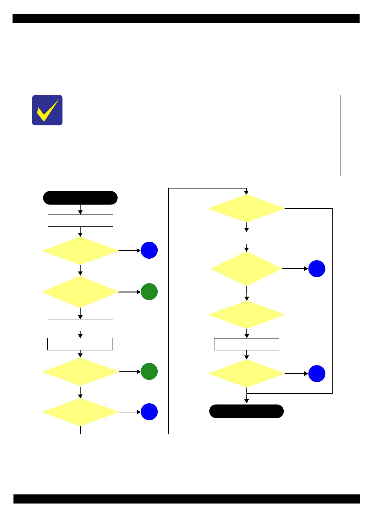
This flowchart is compiled based on the following contents.
• Our experience regarding the quality problem
• ESK’s repair data
• Printer Mechanism specification for WF-7720/WF-7710/WF-7210 Series
WF-7210 Series does not have the Scanner/ADF unit, so the troubleshooting for the
Scanner/ADF unit is not applicable to this series.
If the reason for the return is evident, first check the phenomenon user claims recurs,
then proceed to the troubleshooting.
5
What is returned reason?
2
Standby condition
3
Is printing operation
finished without error?
Start
Turn on the printer
1
4
(p 11)
(p 11)
(p 11)
(p 12)
(p 12)
Copy an image
*: In case of “Not Trouble Found”, check fatal error code.
6
(p 12)
ADF/Scanner
unit failure
Printer failure only
Yes
No
Yes
No
Yes
Yes
No
Yes
Yes
No
No
No
No
Yes
Does printer turn on the
power?
Is Power-on sequence
finished without error?
Print check pattern
Is printing operation
finished without trouble?
Is scanning operation
finished without
trouble?
Is ADF operation finished
without trouble?
Copy an image by ADF
ADF failure?
Finish
*
1.1 Troubleshooting
This section describes the troubleshooting workflow.
1.1.1 Troubleshooting Workflow
The following page describes the troubleshooting workflow. Follow the flow when troubleshooting problems.
Revision A
Figure 1-1. Troubleshooting Workflow (1)
Troubleshooting Troubleshooting Workflow 10
Confidential
Epson WF-7720 / WF-7710 / WF-7210 Series Revision A
The power-on
1
sequence does not
start (p 10)
No Power
[Presumable Cause]
• Power Supply Unit
damage
• Main Board damage
• Panel Unit damage
[Major Troubleshooting]
• Power Supply Unit
replacement
• Main Board
replacement
• Panel Unit replacement
* : If the printer can turn on but turns
off right away, the protection
circuit may cut off the power due
to an error such as a circuit
failure.
*
Please refer to " 1.3 Fatal Error
Code List (p15)"for
troubleshooting.
2
Fatal error
Error is indicated during
power-on sequence (p 10)
Maintenance error
[Occurrence Condition]
This error occurs when
maintenance counter in
EEPROM exceeds the specified
value.
[Major Occurrence Timing]
• Power-on timing
• Print start timing
• Paper eject timing
• Cleaning timing
• Ink cartridge replacement
timing
[Major Troubleshooting]
• Replace Maintenance Box
• Paper Guide Lower Porous
Pad replacement
• Maintenance counter reset
(only Paper Guide Lower
Porous Pad)
No Maintenance Box error
[Occurrence Condition]
This error occurs when
Maintenance Box is not installed.
[Major Occurrence Timing]
• At power-on
• Maintenance Box monitoring
timing
[Major Troubleshooting]
Turn the printer off once and
install Maintenance Box again,
and turn the power on.
Maintenance Box detection
[Occurrence Condition]
This error occurs when
Maintenance Box data is incorrect
or it is not recognized correctly.
[Major Occurrence Timing]
• Power-on timing
• Maintenance Box replacement
• Maintenance Box monitoring
[Major Troubleshooting]
• Remove and reinstall
• Maintenance Box replacement
• Relay Board CSIC Terminal
• Relay Board Assy replacement
• Relay Board FFC replacement
• Main Board replacement
error
timing
timing
Maintenance Box
replacement
Ink End error
[Occurrence Condition]
This error occurs when ink in Ink
cartridge is empty.
[Major Occurrence Timing]
• Power-on timing
• Print start timing
• Print timing
• Cleaning timing
• Ink cartridge replacement
timing
[Major Troubleshooting]
Ink cartridge replacement
[NOTE]
If an error occurs during
printing, the page where the error
occurred is skipped and the
printing resumes from the next
page.
Ink cartridge detection error
[Occurrence Condition]
This error occurs when Ink
cartridge data is incorrect or Ink
cartridge is not recognized
correctly.
[Major Occurrence Timing]
• Power-on timing
• Print start timing
• Cleaning timing
• Ink cartridge replacement
timing
[Major Troubleshooting]
• Remove and reinstall Ink
cartridge.
• Ink cartridge replacement
• CSIC Terminal replacement
• CR Contact Module
replacement
• Head FFC replacement
• Main Board replacement
No Ink cartridge error
[Occurrence Condition]
This error occurs when Ink
cartridge is not installed.
[Major Occurrence Timing]
At power-on
[Major Troubleshooting]
Install Ink cartridge
Cover open error
[Occurrence Condition]
This error occurs when Scanner
Unit (Printer Cover) is open.
[Major Occurrence Timing]
• At power-on
• During printing
[Major Troubleshooting]
• Close Scanner Unit (Printer
Cover) replacement
• Scanner Unit (Printer Cover)
replacement
• Cover Open Sensor
replacement
• Main Board replacement
Paper Jam error
Please refer to " Paper Jam
error".
CR Fixing Tape error
[Occurrence Condition]
This error occurs if a paper jam
occurs during the power-on
sequence before initial ink
charge.
[Major Occurrence Timing]
Power-on timing
(before initial ink charge)
[Major Troubleshooting]
Open the scanner unit and
remove the CR fixing tape.
Error is indicated during printing nozzle check pattern (p 10)
3
Paper Jam error
[Occurrence Condition]
This error occurs when top/bottom of
paper is not detected by PE Sensor in the
specified steps of paper feeding
operation correctly.
[Major Occurrence Timing]
• Power-on timing
• Paper loading timing
• Paper eject timin g
• Duplex print timing
[Major Troubleshooting]
1 remove the jammed paper by opening
Scanner Unit or Printer Cover.
2 Push “Start” button.
3 If not resolved by 2), check the
following.
• Foreign material, bits of paper
• Part come-off
• PE Lever
• PE Sensor
• Float of Paper Guide Front Porous
Pad
•Main Board
• PW Sensor
[NOTE]
* If an error occurs during printing, the
page where the error occurred is skipped
and the printing resumes from the next
page.
* If an error occurs during duplex
printing, the following are performed.
• If an error occurs during the front
face of duplex printing, the page
where the error occurred and the
next page are skipped and the
printing resumes from the page
after the next.
• If an error occurs during the back
face of duplex printing, the page
where the error occurred is skipped
and the printing resumes from the
next page.
No Paper error
[Occurrence Condition]
This error occurs when top of
paper is not detected by PE Sensor
in the specified steps of paper
loading operation correctly.
[Major Occurrence Timing]
Paper loading timing
[Major Troubleshooting]
1 Put paper in cassette and push
“START” button.
2 If a paper stops before reaching
PE Sensor, remove it and
check the paper condition.
3 A) If no damage on the paper, s et
edge guide correctly after
putting paper in ca ssette and
push “PRINT” button again.
B) If damage on the paper, check
foreign materials / parts come off / parts transforma tion in
paper path.
4 If not resolved by 3-A) & 3-B),
check the following.
• Pickup Roller
• Duplex Unit
• PE Sensor
• Main Board
• PF Motor
• Casette Assy
Double Feed error
[Occurrence Condition]
This error occurs on the following
cases.
• A paper is ejected without
printing during paper loading
operation.
• Actual paper length is longer
than theoretical one.
[Major Occurrence Timing]
Paper loading timing
[Major Troubleshooting]
• PE Lever replacement
• PE Sensor replacement
• PW Sensor replacement
• Main Board replacement
[NOTE]
This error occurs only for manual
duplex print.
No Paper Cassette error
[Occurrence Condition]
This error occurs if one of the
cassettes is not installed.
[Major Occurrence Timing]
Paper loading timing
(Front loading)
[Major Troubleshooting]
Install the Cassette Assy.
Paper Size Unmatch error
[Occurrence Condition]
This error occurs when actual
paper size is not matched to
theoretical one.
[Major Occurrence Timing]
• Duplex print timing
• FAX data print timing
[Major Troubleshooting]
1 Put correct sized paper in
cassette, and push “START”
button.
2 If not resolved by step 1),
check the following points.
• PE Lever
•PE Sensor
• PW Sensor
• Main Board
Manual Tray No Paper error
[Occurrence Condition]
When printing from Manual Tray
(MSF unit), this error occurs if
paper is not loaded at the time of
data transmission.
[Major Occurrence Timing]
Paper loading timing
(Rear loading)
[Major Troubleshooting]
• Put paper in the Manual Tray
(MSF unit).
• PE Sensor replacement
• PW Sensor replacement
• Main Board replacement
Manual Feed Request error
[Occurrence Condition]
This error occurs if the printer
cannot receive the manual feed
request.
[Major Occurrence Timing]
Paper loading timing
(Rear loading)
[Major Troubleshooting]
• Send the print data.
• Main Board replacement
Excessive Manual Feed Error
[Occurrence Condition]
This error occurs when the PE
Sensor detects paper before
manual feed or when paper is
inserted too much.
[Major Occurrence Timing]
Print start timing (Rear loading)
[Major Troubleshooting]
• Eject paper with panel
operation, and load paper
again.
• Main Board replacement
• PE Sensor replacement
• PE Lever replacement
Insufficient Manual Feed
[Occurrence Condition]
This error occurs during manual
feed if the PE Sensor detects
paper but the paper is not fed by
auto loading.
[Major Occurrence Timing]
Print start timing (Rear loading)
[Major Troubleshooting]
Eject paper with panel operation,
and load paper again.
error
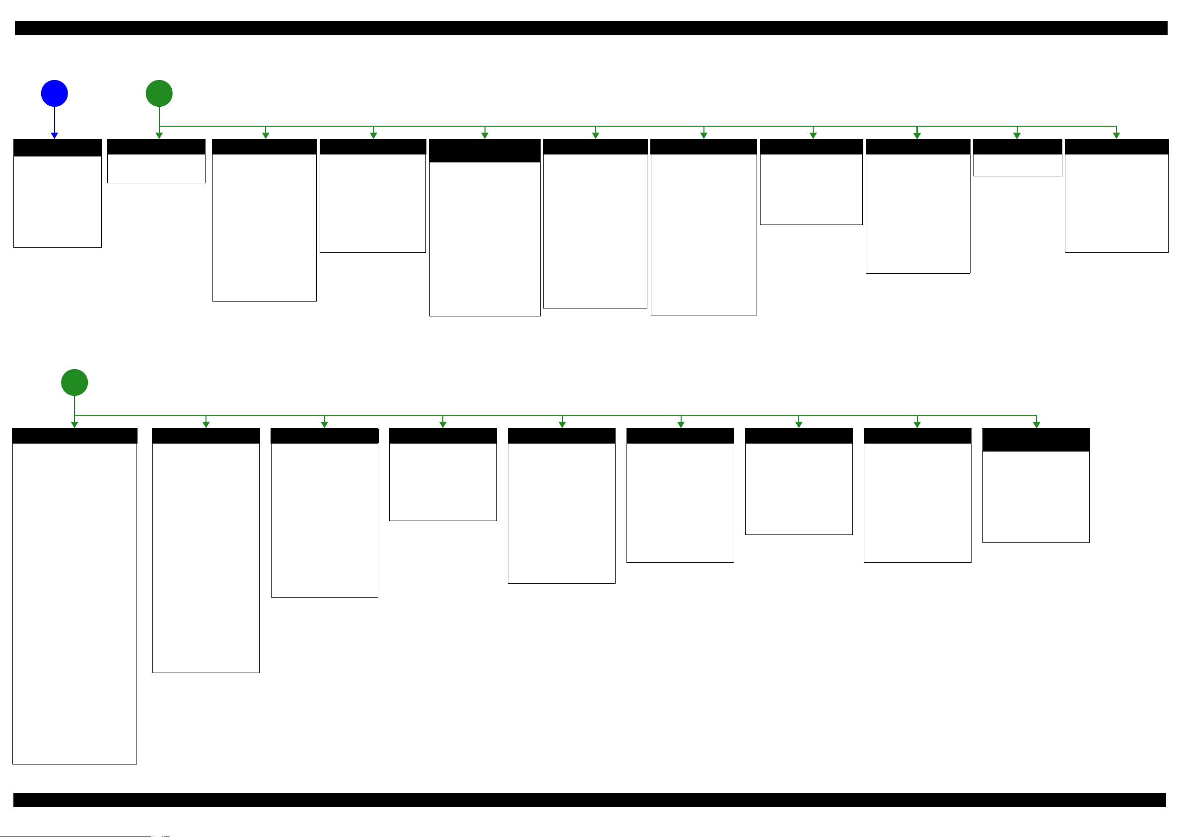
Figure 1-2. Troubleshooting Workflow (2)
Appendix Troubleshooting Workflow 11
Confidential
Epson WF-7720 / WF-7710 / WF-7210 Series Revision A
Problems related to print result or during printing(p 10)
4
Poor Printing
[Phenomenon]
• Poor printing quality
• Ink stain on paper
• Dot missing
• Paper eject without printing
[Presumable Cause]
• Driver / Panel mis-setting
• Contamination of CR scale
• Contamination of Printhead
Cover
• Printhead damage
• Ink clogging of Printhead
• Contamination on Cap Unit /
Wiper of Ink system Assy
• Ink system Assy damage
• Float of Paper Guide Front
Porous Pad
• Narrow PG
• PE Lever damage
• PE Sensor damage
• PW Sensor damage
[Major Troubleshooting]
• Driver / Panel re-setting
• CR Scale replacement
• Printhead cover cleaning
• Printhead cleaning
• Ink cartridge replacement
• Printhead replacement
• Rubber cleaning of Cap Unit of
Ink system Assy
• Ink system Assy replacement
• Paper Guide Front Porous Pad
re-installation
• PG readjustment
• Printer Mechanism
replacement
• PE Lever replacement
• PE Sensor replacement
• PW Sensor replacement
Poor Paper Loading
[Presumable Cause]
• Use of 3rd party media
• Edge guide mis-setting
• Foreign material
• Part come-off
• Contamination of paper feed
roller (Duplex Unit)
• Cassette Assy damage
• Pickup Roller deterioration,
contamination
• Contamination of PF roller
[Major Troubleshooting]
• Recommendation of EPSON
media
• Edge guide re-setting
• Foreign material removal
• Part re-installat ion
• PF Roller replacement
• Cassette Assy replacement
• Pickup Roller replacement
Abnormal Noise
[Presumable Cause]
• Foreign material
• Insufficient grease
• Gear damage
[Major Troubleshooting]
• Foreign material removal
• Lubrication of grease
• Gear replacement
Scanning cannot be
performed
5
successfully (p 10)
Scanner failure
[Presumable Cause]
• Contamination of Scanner
Glass
• Contamination of Document
Pad
• CIS Unit bonding failure
• CIS Unit damage
• Scanner Motor damage
[Major Troubleshooting]
• Scanner Glass cleaning
• Document Pad cleaning
• Document Pad replacement
• CIS Unit replacement
• Scanner Motor replacement
ADF does not operate
6
normally (p 10)
ADF failure
[Phenomenon]
• No paper feed
• Double feed
• Paper jam
• Paper skew
[Presumable Cause]
• Wear of Pickup Roller
• Wear of ADF Pad Assy
•Gear damage
• ADF Motor damage
• Contamination of Scanner Glass
• ADF Paper Support Assy
damage
• Foreign material
• ADF Cover Assy damage
• Wear of EJ Roller
• ADF Sensors damage
[Major Troubleshooting]
• ADF Cover Assy replacement
• ADF Pad Assy replacement
• Scanner Glass cleaning
• ADF Paper Support Assy
replacement
• Foreign material removal
• ADF Unit replacement
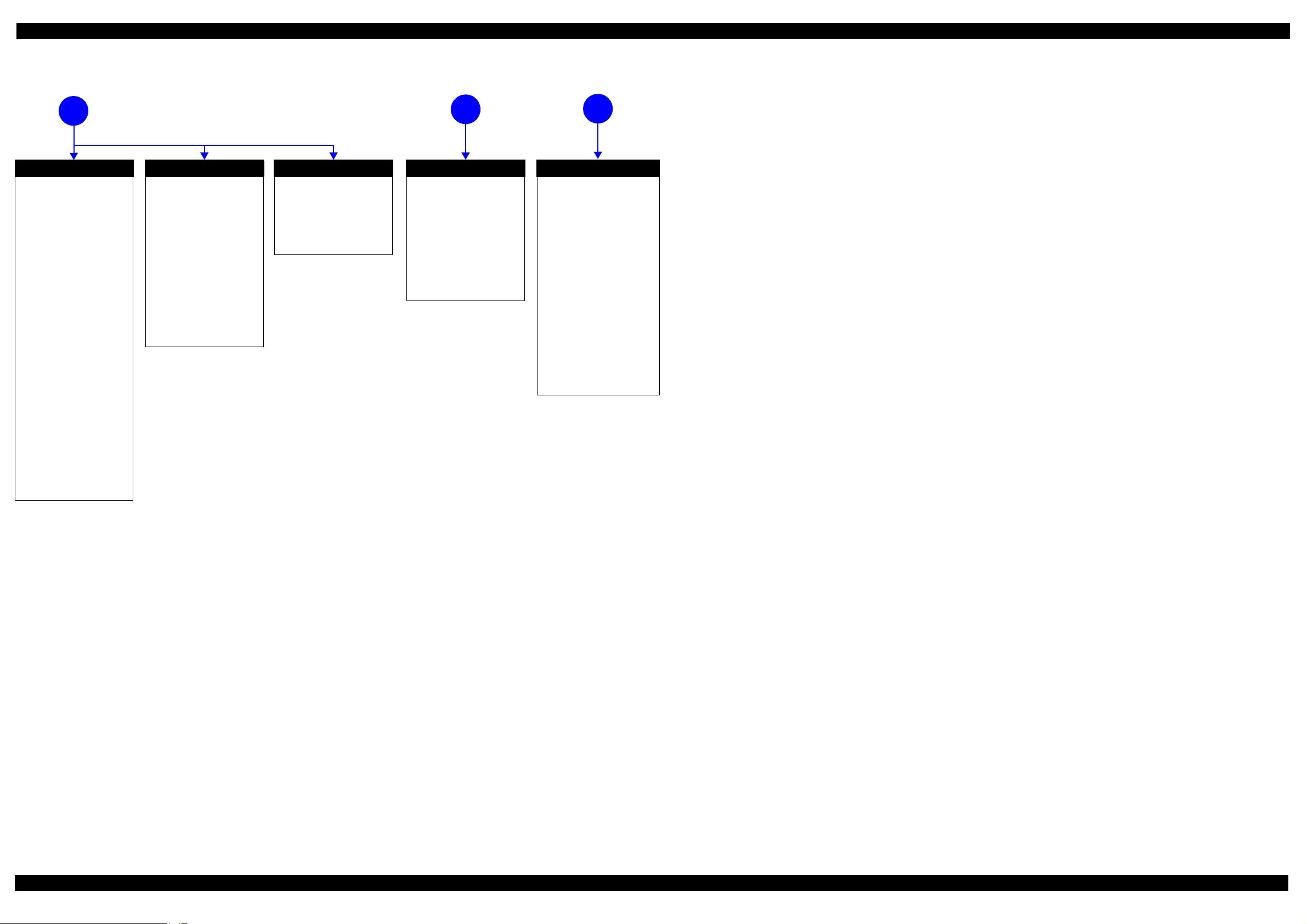
Figure 1-3. Troubleshooting Workflow (3)
Appendix Troubleshooting Workflow 12
Confidential

Epson WF-7720 / WF-7710 / WF-7210 Series Revision A
1.2 Power-On Sequence
This section describes the power-on sequences for this product. The preconditions are as follows.
Normal power-on sequence (See Table 1-1.)
Turning on the printer after turning it off without an error.
Initial ink charge has finished and every cartridge has sufficient ink.
No paper on the paper path.
The Printhead is capped by the cap of the Ink System and the CR Lock is engaged normally.
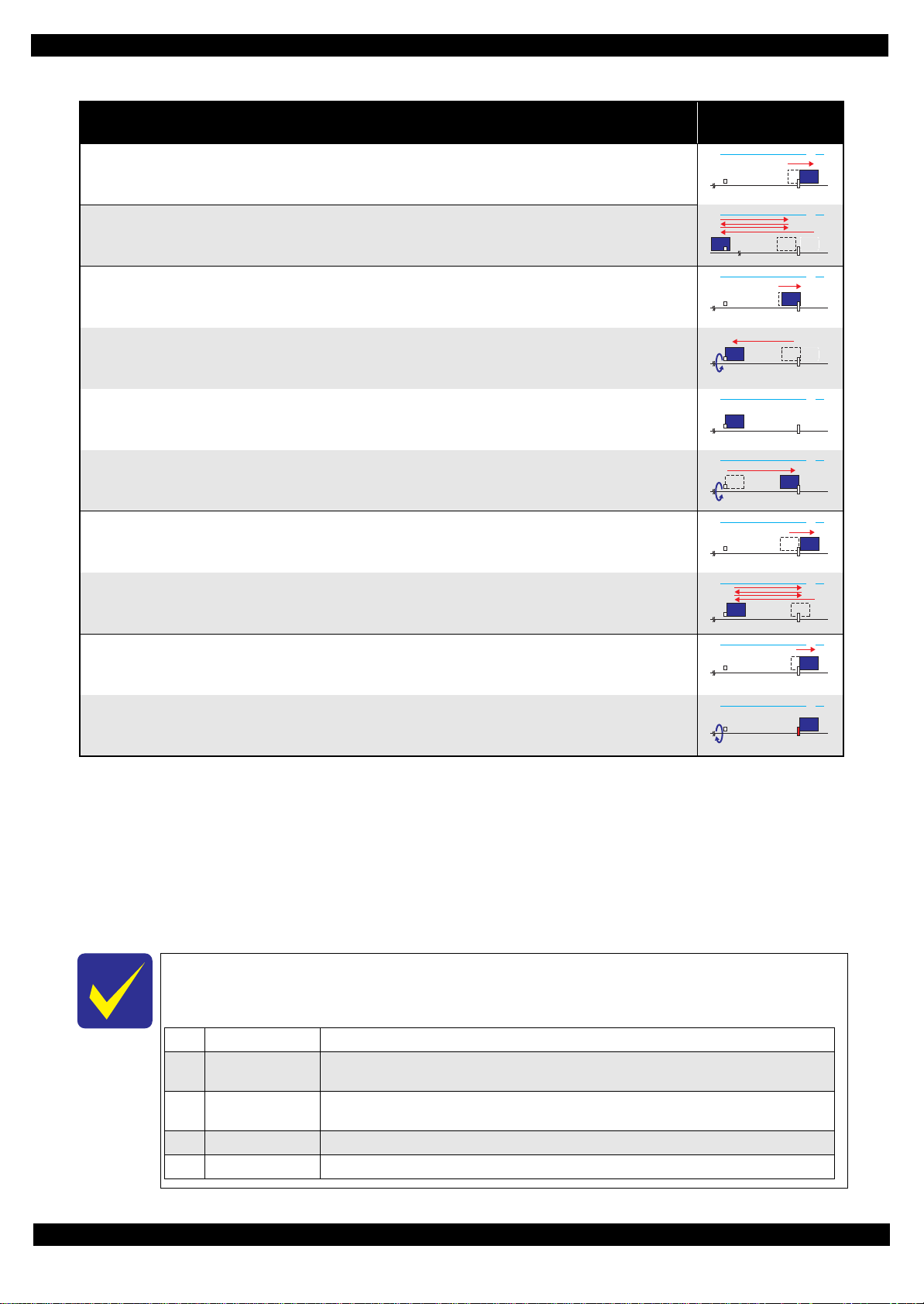
Table 1-1. Normal Power-on Sequence
Operation
1. Printhead initialization
1. Initializes the Printhead.
2.Checking for waste ink overflow
1. Checks the waste ink counter if the waste ink overflow is occurring.
*3
*1
CR Unit/PF Roller
movement and position
HP
CRUnit
APGLever CRLock
*
2
0130
0130 HP
3.Avoiding deadlock sequence
*4
1. The CR Unit moves to the 0-digit side slowly and confirms it touches the Right Frame.
2. The CR Unit moves to the 80-digit side up to its home position.
3. The PF Motor rotates clockwise, and releases the CR lock.
4.Seeking the home position
1. The carriage moves to the 0-digit side slowly and confirms it touches the Right Frame.
2. By regarding the position where the CR Unit touches the Right Frame as the specified distance from the origin, the
home position is determined. Thereafter, the position of the CR Unit is monitored based on the information provided
by the CR Encoder.
3. The CR Unit slowly moves to its home position.
5.PF initialization
1. The CR Unit moves slowly about 3 cm to the 130-digit side.
2. The PF Roller rotates counterclockwise quickly.
0130 HP
0130 HP
0130 HP
0130 HP
0130 HP
0130 HP
0130 HP
0130 HP
3. The CR Unit moves to ASF trigger ON => OFF positions.
4. The PF Motor rotates clockwise for approx. one second.
5. The PF Roller rotates clockwise for about one second.
6. The PE sensor detects if paper exists and the PF Motor rotates clockwise for approx. 0.5 second.
*5
0130 HP
0130 HP
0130 HP
0130 HP
Appendix 13
Confidential
Epson WF-7720 / WF-7710 / WF-7210 Series Revision A
0130 HP
1Prior to Step 1 Initializes the APG Lever.
2 Prior to Step 2
The CR Unit evacuates to the 130-digit side once, and the PF Roller rotates clockwise once, then the cap unit of
the Ink System is lowered, and then the CR Unit touches the Right Frame once again for confirmation.
3Prior to Step 3
The CR Unit moves to its CR Lock Position (130-digit side), and the PF Roller rotates
counterclockwise to engage the CR Lock. Then the CR Unit touches the CR Lock for confirmation.
4 Prior to Step 5 Initializes the APG unit (set to PG1 position).
5Prior to Step 9 Measurement of the CR Motor
Table 1-1. Normal Power-on Sequence
CR Unit/PF Roller
movement and position
*
2
0130 HP
6.Low temperature operation sequence
7. The CR Unit returns its home position.
Operation
*6
*1
8. The CR Unit moves between around the switch lever and in front of the Left Frame two times.
7.PF measurement and PW sensor initialization
9. The CR Unit slightly moves to the 0-digit side.
10.The carriage moves to the VHCheck position (130-digit side) quickly and stops; meanwhile the voltage values
detected by the PW sensor at the specified three points are recorded. At the same time, the PF Motor rotates
clockwise and measures the load.
11.The CR Unit detects the voltage of the PW sensor at the carriage stop position (the black area at the Paper Guide
Front).
12.The CR Unit returns near its home position. At the same time, the PF Motor rotates clockwise and measures the
load.
8.Detecting ink cartridge and initializing ink system
*7
13.The CR Unit slowly returns to its home position.
14.To check the operation of the PIS Sensor and to detect ink, the CR Unit moves back and forth between the CR Unit
and near the APG Lever for two times.
9. CR lock setting
15.The CR Unit moves to its home position.
0130 HP
0130 HP
0130 HP
0130 HP
0130 HP
0130 HP
0130 HP
16.The PF Roller rotates counterclockwise to lock the CR Unit with the CR Lock.
Note *1: The rotation directions of the PF Motor are as follows.
Clockwise: Paper is fed normally
Counterclockwise: Paper is fed backward
*2: The conditions of the CR lock are as follows.
Red CR lock is set
White CR lock is released
*3: If it cannot be initialized, the fatal error occurs.
*4: Confirm that the CR lock is not get stuck in the gap of the carriage or any other parts preventing the carriage from moving.
*5: Eject paper if any.
*6: Executed when the detected temperature is under 5
o
C (41oF) by the thermistor on the Printhead.
*7: The empty suction operation may occur depending on situations.
The power-on sequence shown in Table 1-1 is the sequence for when the previous power-off is
complete normally as indicated in the conditions. If the previous power-off ends abnormally,
operations including initialization of APG and such are performed in the following steps.
0130 HP
Appendix 14
Confidential

Epson WF-7720 / WF-7710 / WF-7210 Series Revision A
1.3 Fatal Error Code List
This section describes how to check the fatal error code, description, and the possible causes.
1.3.1 Displaying the Fatal Error Code
The fatal error code is stored in the EEPROM on the Main Board and can be read out using the Adjustment
Program. This product displays a printer fatal error code automatically on the panel LCD when a printer fatal
error occurs.
Figure 1-4. Displaying the Fatal Error Code
Appendix Displaying the Fatal Error Code 15
Confidential

Epson WF-7720 / WF-7710 / WF-7210 Series Revision A
1.3.2 Fatal Error Code
This section describes the fatal error code and the possible cause for this product.
" ADF/Scanner (p16)"
" Printer (CR) (p21)"
" Printer (PF) (p23)"
" Printer (ASF) (p25)"
" Printer (PE/Head/CSIC) (p26)"
" Printer (others) (p27)"
" System Error (p28)"
Fatal errors related to the ADF/Scanner unit do not occur for WF-7210 Series because this
model does not have ADF/Scanner unit.
1.3.2.1 ADF/Scanner
Error
code
100001
100002
100003
Error name Possible cause Confirmation procedure
1.Clean the ADF encoder scale if it is
contaminated.
2.Check the cable/FFC of the ADF motor/encoder.
3.Replace the ADF encoder sensor with a new one.
4.Replace the main board with a new one.
1.Check that no pieces of paper or foreign objects
exist in the paper path.
2.Check the load of the ADF paper feed
mechanism.
3.Check the ADF drive gear wheel train.
4.Clean the ADF encoder scale if it is
contaminated.
5.Check the cable/FFC of the ADF motor/encoder.
6.Replace the ADF encoder sensor with a new one.
7.Replace the main board with a new one.
1.Check that no jammed paper exist in the paper
path.
2.Check the load of the ADF.
3.Check the ADF drive gear wheel train.
4.Clean the ADF encoder scale if it is
contaminated.
5.Check the cable/FFC of the ADF motor/encoder.
6.Replace the ADF encoder sensor with a new one.
7.Check the connector of the ADF motor.
8.Replace the ADF motor with a new one.
9.Replace the main board with a new one.
ADF PID
excess speed
error
ADF PID
reverse error
ADF PID lock
error
Failed to read the ADF motor encoder
1. Contamination of the ADF encoder scale
2. Damage or skew of the ADF encoder FFC
3. Failure of the ADF encoder sensor
Failure of the ADF motor driver
4. Failure of the main board
Paper feed fails, stopped by obstacles
1. Paper feed was stopped by;
• Obstacles such as jammed paper
• Overload of the paper feed mechanism
• Disengaging or tooth breakage of wheel train
of the paper feed mechanism
Failed to read the PF motor encoder
2. Jumping of the ADF timing belt
3. Contamination of the ADF encoder scale
4. Damage or skew of the ADF encoder FFC
5. Failure of the ADF encoder sensor
6. Failure of the main board
The ADF motor did not run or obstacles exist in the
paper path
1. Overload of the paper feed mechanism
2. The ADF timing belt become frayed, jumping, or
the wheel train of paper feed mechanism is
disengaged or its tooth is broken
Failed to read the ADF motor encoder
3. Contamination of the ADF encoder scale
4. Disconnection, break, skew or damage of the
ADF encoder FFC
5. Failure of the ADF encoder sensor
6. Failure of the ADF motor (the lead wire is broken
or the connector is disconnected)
7. Failure of the main board
Connector
No.
Main board
CN33
CN73
Main board
CN33
CN73
Main board
CN33
CN73
Appendix Fatal Error Code 16
Confidential

Epson WF-7720 / WF-7710 / WF-7210 Series Revision A
Error
code
100004
100005
100006
100009
Error name Possible cause Confirmation procedure
1.Check that no jammed paper exist in the paper
path.
2.Check the load of the ADF.
3.Check the ADF drive gear wheel train.
4.Clean the ADF encoder scale if it is
contaminated.
5.Check the cable/FFC of the ADF motor/encoder.
6.Replace the ADF encoder sensor with a new one.
7.Check the connector of the ADF motor.
8.Replace the ADF motor with a new one.
9.Replace the main board with a new one.
1.Check that no pieces of paper or foreign objects
exist in the paper path.
2.Check the load of the ADF paper feed
mechanism.
3.Check the ADF drive gear wheel train.
4.Check the ADF encoder scale for damage or
contamination.
5. Check the cable/FFC of the ADF motor/encoder.
6.Replace the ADF motor with a new one.
7.Replace the main board with a new one.
1.Turn the printer off and back it on.
2.If the error still occurs after the restart, replace the
main board.
1.Clean the ADF encoder scale if it is
contaminated.
2. Check the cable/FFC of the ADF motor/encoder.
3.Replace the ADF encoder sensor with a new one.
4.Replace the main board with a new one.
ADF PID
acceleration
lock error
ADF PID
excess load
error
ADF PID
driving time
error
ADF BS+
excess speed
error
The ADF motor did not run or obstacles exist in the
paper path
1. Overload of the paper feed mechanism
2. The ADF timing belt become frayed, jumping, or
the wheel train of paper feed mechanism is
disengaged or its tooth is broken
Failed to read the ADF motor encoder
3. Contamination of the ADF encoder scale
4. Disconnection, break, skew or damage of the
ADF encoder FFC
5. Failure of the ADF encoder sensor
6. Failure of the ADF motor (the lead wire is broken
or the connector is disconnected)
7. Failure of the main board
The ADF motor stopped running in the middle of the
operation
1. The ADF was stopped by;
• Obstacles such as jammed paper
• Overload of the paper feed mechanism
• Disengaging or breakage of the gears
Failed to read the ADF motor encoder
2. The timing belt become frayed or jumping
3. Contamination of the ADF encoder scale
4. Disconnection, break, skew or damage of the
ADF motor cable/encoder FFC
5. Failure of the ADF motor (not completely broken)
6. Failure of the main board
Malfunction or crash of the firmware
Failed to read the ADF motor encoder
1. Contamination of the ADF encoder scale
2. Damage or skew of the ADF encoder FFC
3. Failure of the ADF encoder sensor
Failure of the ADF motor driver
4. Failure of the main board
Connector
No.
Main board
CN33
CN73
Main board
CN33
CN73
---
Main board
CN33
CN73
100010
100011
ADF BS+
reverse error
ADF BS+ lock
error
Paper feed fails, stopped by obstacles
1. Paper feed was stopped by;
• Obstacles such as jammed paper
• Overload of the paper feed mechanism
• Disengaging or tooth breakage of wheel train
of the paper feed mechanism
Failed to read the ADF motor encoder
2. Jumping of the ADF timing belt
3. Contamination of the ADF encoder scale
4. Damage or skew of the ADF encoder FFC
5. Failure of the ADF encoder sensor
6. Failure of the main board
The ADF motor did not run
1. The ADF was stopped by;
• Obstacles such as jammed paper
• Overload of the mechanism
• Disengaging or breakage of the gears
Failed to read the ADF encoder
2. Contamination of the ADF encoder scale
3. Disconnection, break, skew or damage of the
ADF motor cable/encoder FFC
4. Failure of the ADF encoder sensor
5. Failure of the ADF motor (the lead wire is broken
or the connector is disconnected)
6. Failure of the main board
1.Check that no pieces of paper or foreign objects
exist in the paper path.
2.Check the load of the ADF paper feed
mechanism.
3.Check the ADF drive gear wheel train.
4.Clean the ADF encoder scale if it is
contaminated.
5. Check the cable/FFC of the ADF motor/encoder.
6.Replace the ADF encoder sensor with a new one.
7.Replace the main board with a new one.
1.Check that no pieces of paper or foreign objects
exist in the paper path.
2.Check the ADF drive gear wheel train.
3.Clean the ADF encoder scale if it is
contaminated.
4.Check the cable/FFC of the ADF motor/encoder.
5.Replace the ADF encoder sensor with a new one.
6.Replace the ADF motor with a new one.
7.Replace the main board with a new one.
Main board
CN33
CN73
Main board
CN33
CN73
Appendix Fatal Error Code 17
Confidential

Epson WF-7720 / WF-7710 / WF-7210 Series Revision A
Error
code
100013
100014
100016
Error name Possible cause Confirmation procedure
1.Check that no pieces of paper or foreign objects
exist in the paper path.
2.Check the load of the ADF paper feed
mechanism.
3.Check the ADF drive gear wheel train.
4.Clean the ADF encoder scale if it is
contaminated.
5.Replace the ADF motor with a new one.
6.Replace the main board with a new one.
1.Turn the printer off and back it on.
2.If the error still occurs after the restart, replace the
main board.
1.With the document cover opened, turn the power
on.
2.Check if the CIS moves to the left to read the
white standard/home patterns.
3.Check if the CIS's emission color is white (not
greenish, reddish, or bluish).
If the light does not look like white, check the
scanner FFC for damage, disconnection or skew.
4.Replace the scanner unit with a new one.
5.Replace the main board with a new one.
ADF BS+
excess load
error
ADF BS+
driving time
error
HP detection
failure
The ADF motor stopped running in the middle of the
operation
1. The ADF was stopped by;
• Obstacles such as jammed paper
• Overload of the paper feed mechanism
• Disengaging or breakage of the gears
Failed to read the ADF motor encoder
2. Jumping of the timing belt
3. Contamination of the ADF encoder scale
4. Failure of the ADF motor (not completely broken)
5. Failure of the main board
Malfunction or crash of the firmware
The scanner CR could not return to its home.
1. Damage or disengaging of wheel train of the drive
mechanism
2. Disengaging, fraying, jumping of the timing belt
Failed to read the white standard/home patterns
3. Disconnection, break, skew or damage of the
scanner FFC
4. Failure of the CIS unit
5. Failure of the scanner housing
6. Failure of the main board
Connector
No.
Main board
CN33
CN73
---
Main board
CN32
CN70
100017
100018
100019
Contact
detection
distance
exceeded
Opposite side
contact
detection
distance
exceeded error
Wrong contact
detection
distance error
The scanner CR cannot completely reach the home
(left side)
1. Damage or disengaging of wheel train of the drive
mechanism
Failed to read the scanner encoder
2. Damage or skew of the scanner FFC
3. Failure of the CIS unit
4. Failure of the scanner housing
5. Failure of the main board
The scanner CR cannot completely reach the opposite
side of the home (right side)
1. Damage or disengaging of wheel train of the drive
mechanism
Failed to read the scanner encoder
2. Damage or skew of the scanner FFC
3. Failure of the CIS unit
4. Failure of the scanner housing
5. Failure of the main board
1.CIS Unit failure
2. Scanner Housing failure (Including wrong attachment of
the origin mark)
3.Main Board failure
4.Scanner FFC failure / Scanner FFC connection failure
5.Scanner Motor failure / Scanner Motor connection
failure
1.With the document cover opened, turn the power
on.
2.Check if the CIS (CR) reaches (comes in contact
with) the left side.
3.Check the wheel train of the drive mechanism for
damage.
4.Check the scanner FFC for damage,
disconnection or skew.
5.Replace the scanner unit with a new one.
6.Replace the main board with a new one.
1.With the document cover opened, turn the power
on.
2.Check if the CIS (CR) reaches (comes in contact
with) the right side.
3.Check the wheel train of the drive mechanism for
damage.
4.Check the scanner FFC for damage,
disconnection or skew.
5.Replace the scanner unit with a new one.
6.Replace the main board with a new one.
1.Check the connector of Scanner Motor
2.Check the cable/FFC of the Scanner motor.
3.Replace the scanner unit with a new one.
4.Replace the main board with a new one.
Main board
CN32
CN70
Main board
CN32
CN70
Main board
CN32
CN70
1.Check if the CIS (CR) moves or not.
• Check the timing belt for fraying or
looseness.
• Check the wheel train of the drive
mechanism for damage.
2.Replace the scanner unit with a new one.
3.Replace the main board with a new one.
---
100020
Overload of the scanner drive mechanism
Failure of the scanner motor
Measurement
error
Appendix Fatal Error Code 18
Confidential

Epson WF-7720 / WF-7710 / WF-7210 Series Revision A
Error
code
100032
100054 Paper jam error
100065
100066
Error name Possible cause Confirmation procedure
LED light
failure
FB PID excess
speed error
FB PID reverse
error
Failure of the CIS LED light (RGB)
1. Disconnection, break, skew or damage of the
scanner FFC
2. Failure of the CIS unit
3. Failure of the main board
No jammed paper is remaining but the sensor does
not turn off
1. Failure of the ADF PE sensor
2. Failure of the cable
Jammed paper is remaining
The paper feed rollers and paper conveying rollers
slip too much
• At power-on
• during paper feed
• during scanning
Failed to read the scanner encoder
1. Contamination of the scanner encoder scale
2. Damage or skew of the scanner FFC
3. Failure of the scanner encoder sensor
Failure of the scanner motor driver
4. Failure of the main board
Operation failure of the scanner motor
1. The scanning operation was stopped by;
• Disengaging of the scanner CR
• Disengaging of the scanner motor pulley or
cracking of the scanner motor gears
Failed to read the scanner encoder
2. Contamination of the scanner encoder
3. Damage or skew of the scanner FFC
4. Failure of the scanner encoder sensor
5. Failure of the main board
1.Check the color of the LED at power-on.
2.Check the scanner FFC for damage,
disconnection or skew.
3.Replace the scanner unit with a new one.
4.Replace the main board with a new one.
1.Open the Cover, Paper Guide, LD, ADF and
check i
2.f paper exist or not.
3.Open the Document Support ADF and check if
paper exist or not.
4.Open the ADF and check if paper exist or not.
5.Check if the paper sensor lever moves up and
down.
6.Replace the ADF unit with a new one.
7.Replace the scanner unit with a new one.
8.Replace the main board with a new one.
1.Check the scanner FFC for damage,
disconnection or skew.
2.Replace the scanner unit with a new one.
3.Replace the main board with a new one.
1.Check the scanner FFC for damage,
disconnection or skew.
2.Replace the scanner unit with a new one.
3.Replace the main board with a new one.
Connector
No.
Main board
CN70
Main board
CN71
Main board
CN32
CN70
Main board
CN32
CN70
100067
100068
FB PID lock
error
FB PID
acceleration
lock error
The scanner motor did not run
1. The scanning operation was stopped by;
• Disengaging of the scanner CR
• Disengaging of the scanner motor pulley or
cracking of the scanner motor gears
Failed to read the CR motor encoder
2. Contamination of the scanner encoder
3. Damage or skew of the scanner FFC
4. Failure of the scanner encoder sensor
5. Failure of the scanner motor
6. Failure of the main board
The scanner motor did not run
1. The scanning operation was stopped by;
Disengaging of the scanner CR
Disengaging of the scanner motor pulley or
Failed to read the scanner motor encoder
cracking of the scanner motor gears
2. Contamination of the scanner encoder
3. Damage or skew of the scanner FFC
4. Failure of the scanner encoder sensor
5. Failure of the scanner motor
6. Failure of the main board
1.Check the scanner FFC for damage,
disconnection or skew.
2.Replace the scanner unit with a new one.
3.Replace the main board with a new one.
Main board
CN32
CN70
1.Check the scanner FFC for damage,
disconnection or skew.
2.Replace the scanner unit with a new one.
3.Replace the main board with a new one.
Main board
CN32
CN70
Appendix Fatal Error Code 19
Confidential

Epson WF-7720 / WF-7710 / WF-7210 Series Revision A
Error
code
100069
100070
100073
Error name Possible cause Confirmation procedure
1.Check the scanner FFC for damage,
disconnection or skew.
2.Replace the scanner unit with a new one.
3.Replace the main board with a new one.
1.Turn the printer off and back it on.
2.If the error still occurs after the restart, replace the
main board.
1.Check the scanner FFC for damage,
disconnection or skew.
2.Replace the scanner unit with a new one.
3.Replace the main board with a new one.
FB PID excess
load error
FB PID driving
time error
FB BS+ excess
speed error
The scanner motor stopped running in the middle of
the operation
1. The scanning operation was stopped by;
• Disengaging of the scanner CR
• Disengaging of the scanner motor pulley or
cracking of the scanner motor gears
Failed to read the scanner motor encoder
2. Contamination of the scanner encoder
3. Disconnection, break, skew or damage of the
scanner FFC
4. Failure of the scanner encoder sensor
5. Failure of the scanner motor
6. Failure of the main board
Malfunction or crash of the firmware
Failed to read the scanner encoder
1. Contamination of the scanner encoder scale
2. Damage or skew of the scanner FFC
3. Failure of the scanner encoder sensor
Failure of the scanner motor driver
4. Failure of the main board
Connector
No.
Main board
CN32
CN70
---
Main board
CN32
CN70
100074
FB BS+ reverse
error
Operation failure of the scanner motor
1. The scanning operation was stopped by;
• Disengaging of the scanner CR
• Disengaging of the scanner motor pulley or
cracking of the scanner motor gears
Failed to read the scanner encoder
2. Contamination of the scanner encoder
3. Damage or skew of the scanner FFC
4. Failure of the scanner encoder sensor
5. Failure of the main board
1.Check the scanner FFC for damage,
disconnection or skew.
2.Replace the scanner unit with a new one.
3.Replace the main board with a new one.
Main board
CN32
CN70
Appendix Fatal Error Code 20
Confidential

Epson WF-7720 / WF-7710 / WF-7210 Series Revision A
Error
code
100075
100077
Error name Possible cause Confirmation procedure
1.Check the scanner FFC for damage,
disconnection or skew.
2.Replace the scanner unit with a new one.
3.Replace the main board with a new one.
1.Check the scanner FFC for damage,
disconnection or skew.
2.Replace the scanner unit with a new one.
3.Replace the main board with a new one.
FB BS+ lock
error
FB BS+ excess
load error
The scanner motor did not run
1. The scanning operation was stopped by;
• Disengaging of the scanner CR
• Disengaging of the scanner motor pulley or
cracking of the scanner motor gears
Failed to read the CR motor encoder
2. Contamination of the scanner encoder
3. Damage or skew of the scanner FFC
4. Failure of the scanner encoder sensor
5. Failure of the scanner motor
6. Failure of the main board
The scanner motor stopped running in the middle of
the operation
1. The scanning operation was stopped by;
• Disengaging of the scanner CR
• Disengaging of the scanner motor pulley or
Failed to read the scanner motor encoder
cracking of the scanner motor gears
2. Contamination of the scanner encoder
3. Disconnection, break, skew or damage of the
scanner FFC
4. Failure of the scanner encoder sensor
5. Failure of the scanner motor
6. Failure of the main board
Connector
No.
Main board
CN32
CN70
Main board
CN32
CN70
100078
FB BS+ driving
time error
1.3.2.2 Printer (CR)
Error
code
000020
000021
000022
Error name Possible cause Confirmation procedure
CR PID driving
time error
CR PID excess
load error
CR PID excess
speed error
Malfunction or crash of the firmware
Malfunction or crash of the firmware
The CR motor stopped running in the middle of the
operation
1. The CR was stopped by;
• Obstacles such as jammed paper
• Overload of the mechanism
• Interfere with the ink system
• Disengaging, fraying , jum p in g of th e timing belt
• Crack or disengaging of the gear, or the APG
lever interferes with the CR
Failed to read the CR encoder
2. Contamination of the CR encoder scale
3. Failure of the CR motor (not completely broken)
4. Failure of the main board
Failed to read the CR encoder
1. Contamination of the CR encoder scale
2. Damage or skew of the CR encoder FFC
3. Failure of the CR encoder sensor
Failure of the CR motor driver
Failure of the main board
1.Turn the printer off and back it on.
2.If the error still occurs after the restart, replace the
main board.
1.Turn the printer off and back it on.
2.If the error still occurs after the restart, replace the
main board.
1.Check that no obstacle exist in the CR motion
range.
2.Check the CR lock and ink system for any
abnormality.
3.Check the timing belt for fraying or looseness.
4.Check the load applied to the CR by moving it by
hand.
5. Check if the lubricant on the CR shaft is adequate.
6.Check the CR drive mechanism.
7.Clean the CR encoder scale if it is contaminated.
8.Replace the CR motor with a new one.
9.Replace the main board with a new one.
1.Clean the CR encoder scale if it is contaminated.
2.Check the FFC of the CR encoder.
3.Replace the CR encoder sensor with a new one.
4.Replace the main board with a new one.
---
Connector
No.
---
---
Main board
CN30
CN43
Appendix Fatal Error Code 21
Confidential

Epson WF-7720 / WF-7710 / WF-7210 Series Revision A
Error
code
000023
000024
Error name Possible cause Confirmation procedure
1.Check that no obstacle exist in the CR motion
range.
2.Check the CR lock and ink system for any
abnormality.
3.Check the timing belt for fraying or looseness.
4.Clean the CR encoder scale if it is contaminated.
5.Check the CR encoder FFC or the connector.
6. Replace the CR encoder sensor with a new one.
7.Replace the main board with a new one.
1.Check that no obstacle exist in the CR motion
range.
2.Move the CR by hand to see if it moves smoothly
without getting stuck.
3.Check the timing belt for fraying or looseness.
4.Clean the CR encoder scale if it is contaminated.
5.Check the connector and the CR encoder FFC for
damage.
6. Replace the CR encoder FFC with a new one.
7.Check the connector of the CR motor.
8.Replace the CR motor with a new one.
9.Replace the main board with a new one.
CR PID reverse
error
CR PID lock
error
Operation failure of the CR motor, stopped by
obstacles
1. CR was stopped by;
• Obstacles such as jammed paper
• Interfere with the ink system
• Disengaging or breakage of the gears
Failed to read the CR encoder
2. Jumping of the CR timing belt
3. Contamination of the CR encoder scale
4. Damage or skew of the CR encoder FFC
5. Failure of the CR encoder sensor
6. Failure of the main board
The CR motor did not run, or the CR could not move
smoothly
1. Overload of the CR
Failed to read the CR encoder
2. The timing belt become frayed or jumping
3. Contamination of the CR encoder scale
4. Disconnection, break, skew or damage of the CR
encoder FFC
5. Failure of the CR encoder sensor
6. Failure of the CR motor (the lead wire is broken
or the connector is disconnected)
7. Failure of the main board
Connector
No.
Main board
CN30
CN43
Main board
CN30
CN43
000025
000030
000031
CR PID speed
fall error
CR load
position driving
time error
CR load
position excess
load error
Operation failure of the CR
1. The CR was stopped by;
Obstacles such as jammed paper
Overload of the mechanism
Interfere with the ink system
Failed to read the CR motor encoder
2. The timing belt become loosened or jumping
3. Contamination of the CR encoder scale
4. Damage or skew of the CR encoder FFC
5. Failure of the CR motor
6. Failure of the main board
Malfunction or crash of the firmware
The CR motor stopped running in the middle of the
operation
1. The CR was stopped by;
• Obstacles such as jammed paper
• Overload of the mechanism
• Interfere with the ink system
• Disengaging or breakage of the gears
• Disengaging, fraying, jumping of the timing
Failed to read the CR encoder
belt
2. Contamination of the CR encoder scale
3. Failure of the CR motor (not completely broken)
4. Failure of the main board
1.Check that no obstacle exist in the CR motion
range.
2.Check the CR lock and ink system for any
abnormality.
3.Check the timing belt for looseness.
4.Clean the CR encoder scale if it is contaminated.
5.Check the connector of the CR encoder FFC.
6.Replace the CR motor with a new one.
7.Replace the main board with a new one.
1.Turn the printer off and back it on.
2.If the error still occurs after the restart, replace the
main board.
1.Check that no obstacle exist in the CR motion
range.
2.Check the CR lock and ink system for any
abnormality.
3.Check the timing belt for fraying or looseness.
4.Check the load applied to the CR by moving it by
hand.
5.Check if the lubricant on the CR shaft is
adequate.
6.Check the CR drive mechanism.
7.Clean the CR encoder scale if it is contaminated.
8.Replace the CR motor with a new one.
9.Replace the main board with a new one.
Main board
CN30
CN43
---
Main board
CN30
CN43
1.Clean the CR encoder scale if it is contaminated.
2.Check the FFC of the CR encoder.
3.Replace the CR encoder sensor with a new one.
4.Replace the main board with a new one.
Main board
CN30
CN43
000032
CR load
position excess
speed error
Failed to read the CR encoder
1. Contamination of the CR encoder scale
2. Damage or skew of the CR encoder FFC
3. Failure of the CR encoder sensor
Failure of the CR motor driver
4. Failure of the main board
Appendix Fatal Error Code 22
Confidential

Epson WF-7720 / WF-7710 / WF-7210 Series Revision A
Error
code
000033
Error name Possible cause Confirmation procedure
CR load
position reverse
error
1.3.2.3 Printer (PF)
Error
code
000040
000041
Error name Possible cause Confirmation procedure
PF PID driving
time error
PF PID excess
load error
Operation failure of the CR motor, stopped by
obstacles
1. CR was stopped by;
• Obstacles such as jammed paper
• Overload of the mechanism
• Interfere with the ink system
Failed to read the CR encoder
2. Jumping of the CR timing belt
3. Contamination of the CR encoder scale
4. Damage or skew of the CR encoder FFC
5. Failure of the CR encoder sensor
6. Failure of the main board
Malfunction or crash of the firmware
• The PE sensor remains in paper detection status
and a paper jam error occurs instead of causing a
fatal error.
The PF motor stopped running in the middle of the
operation
1. The PF was stopped by;
• Obstacles such as jammed paper
• Overload of the paper feed mechanism
• Disengaging or breakage of the gears
Failed to read the PF motor encoder
2. The timing belt become frayed or jumping
3. Contamination of the PF encoder scale
4. Disconnection, break, skew or damage of the PF
motor cable/encoder FFC
5. Failure of the PF motor (not completely broken)
6. Failure of the main board
1.Check that no obstacle exist in the CR motion
range.
2.Check the CR lock and ink system for any
abnormality.
3.Check the timing belt for fraying or looseness.
4.Clean the CR encoder scale if it is contaminated.
5.Check the CR encoder FFC or the connector.
6.Replace the CR encoder sensor with a new one.
7.Replace the main board with a new one.
1.Turn the printer off and back it on.
2.If the error still occurs after the restart, replace the
main board.
1.Check that no pieces of paper or foreign objects
exist in the paper path.
2.Check the load of the paper feed mechanism.
3.Check the wheel train of the PF drive and the
timing belt for fraying or looseness.
4.Check the PF encoder scale for damage or
contamination.
5.Check the PF encoder FFC or the connector.
6.Replace the PF motor with a new one.
7.Replace the main board with a new one.
Connector
No.
Main board
CN30
CN43
Connector
No.
---
Main board
CN31
CN51
000042
000043
PF PID excess
speed error
PF PID reverse
error
Failed to read the PF motor encoder
1. Contamination of the PF encoder scale
2. Skew or damage of the PF encoder FFC
3. Failure of the PF encoder sensor
Failure of the PF motor driver
4. Failure of the main board
Paper feed fails, stopped by obstacles
1. Paper feed was stopped by;
• Obstacles such as jammed paper
• Overload of the paper feed mechanism
• Disengaging or tooth breakage of wheel train
of the paper feed mechanism
Failed to read the PF motor encoder
2. Jumping of the PF timing belt
3. Contamination of the PF encoder scale
4. Skew or damage of the PF encoder FFC
5. Failure of the PF encoder sensor
6. Failure of the main board
1.Clean the PF encoder scale if it is contaminated.
2.Check the PF encoder FFC or the connector.
3.Replace the PF encoder sensor with a new one.
4.Replace the main board with a new one.
1.Check that no pieces of paper or foreign objects
exist in the paper path.
2.Check the load of the paper feed mechanism.
3.Check the wheel train of the PF drive and the
timing belt.
4.Clean the PF encoder scale if it is contaminated.
5.Check the PF encoder FFC or the connector.
6.Replace the PF encoder sensor with a new one.
7.Replace the main board with a new one.
Main board
CN31
CN51
Main board
CN31
CN51
Appendix Fatal Error Code 23
Confidential

Epson WF-7720 / WF-7710 / WF-7210 Series Revision A
Error
code
000044
000050
000051
000052
000053
Error name Possible cause Confirmation procedure
1.Check that no jammed paper exist in the paper
path.
2.Check the load of the PF.
3.Check the wheel train of the PF drive and the
timing belt for fraying or looseness.
4.Clean the PF encoder scale if it is contaminated.
5.Check the PF encoder FFC or the connector.
6.Replace the PF encoder sensor with a new one.
7.Check the connector of the PF motor.
8.Replace the PF motor with a new one
9.Replace the main board with a new one.
1.Turn the printer off and back it on.
2.If the error still occurs after the restart, replace the
main board.
1.Check that no pieces of paper or foreign objects
exist in the paper path.
2.Check the load of the paper feed mechanism.
3.Check the wheel train of the PF drive and the
timing belt for fraying or looseness.
4.Clean the PF encoder scale if it is contaminated.
5.Replace the PF motor with a new one
6.Replace the main board with a new one.
1.Clean the PF encoder scale if it is contaminated.
2.Check the PF encoder FFC or the connector.
3. Replace the PF encoder sensor with a new one.
4.Replace the main board with a new one.
1.Check that no pieces of paper or foreign objects
exist in the paper path.
2.Check the load of the paper feed mechanism.
3.Check the wheel train of the PF drive and the
timing belt for fraying or looseness.
4.Clean the PF encoder scale if it is contaminated.
5.Check the PF encoder FFC or the connector.
6. Replace the PF encoder sensor with a new one.
7.Replace the main board with a new one.
PF PID lock
error
PF load
position driving
time error
PF load
position excess
load error
PF load
position excess
speed error
PF load
position reverse
error
The PF motor did not run or obstacles exist in the
paper path
1. Overload of the paper feed mechanism
2. The PF timing belt become frayed, jumping, or
the wheel train of paper feed mechanism is
disengaged or its tooth is broken
Failed to read the PF motor encoder
3. Contamination of the PF encoder scale
4. Disconnection, break, skew or damage of the PF
encoder FFC
5. Failure of the PF encoder sensor
6. Failure of the PF motor (the lead wire is broken or
the connector is disconnected)
7. Failure of the main board
Malfunction or crash of the firmware
The PF motor stopped running in the middle of the
operation
1. The PF was stopped by;
• Obstacles such as jammed paper
• Overload of the paper feed mechanism
• Disengaging or breakage of the gears
Failed to read the PF motor encoder
2. Jumping of the timing belt
3. Contamination of the PF encoder scale
4. Failure of the PF motor (not completely broken)
5. Failure of the main board
Failed to read the PF motor encoder
1. Contamination of the PF encoder scale
2. Skew or damage of the PF encoder FFC
3. Failure of the PF encoder sensor
Failure of the PF motor driver
4. Failure of the main board
Paper feed fails, stopped by obstacles
1. Paper feed was stopped by;
• Obstacles such as jammed paper
• Overload of the paper feed mechanism
• Disengaging or tooth breakage of wheel train
Failed to read the PF motor encoder
of the paper feed mechanism
2. Jumping of the PF timing belt
3. Contamination of the PF encoder scale
4. Skew or damage of the PF encoder FFC
5. Failure of the PF encoder sensor
6. Failure of the main board
Connector
No.
Main board
CN31
CN51
---
---
Main board
CN31
CN51
Main board
CN31
CN51
Appendix Fatal Error Code 24
Confidential

Epson WF-7720 / WF-7710 / WF-7210 Series Revision A
1.3.2.4 Printer (ASF)
Error
code
000060
000061
000062
000063
000064
000066
Error name Possible cause Confirmation procedure
ASF PID
driving time
error
ASF PID
excess load
error
ASF PID
excess speed
error
ASF PID
reverse error
ASF PID lock
error
ASF PID
torsion limit
error
Malfunction or crash of the firmware
The ASF motor stopped running in the middle of the
operation
1. The ASF was stopped by;
• Obstacles such as jammed paper
• Overload of the mechanism
• Disengaging or breakage of the gears
Failed to read the ASF motor encoder
2. Disconnection or contamination of the ASF
encoder scale
3. Disconnection, break, skew or damage of the ASF
motor cable/ASF encoder FFC
4. Failure of the ASF encoder sensor
5. Failure of the ASF motor (not completely broken)
6. Failure of the main board
Failed to read the ASF motor encoder
1. Contamination of the ASF encoder scale
2. Damage or skew of the ASF motor cable/encoder
FFC
3. Failure of the ASF encoder sensor
Failure of the ASF motor driver
4. Failure of the main board
Paper feed fails, stopped by obstacles
1. The ASF was stopped by;
• Obstacles such as jammed paper
• Overload of the mechanism
• Disengaging or breakage of the gears
Failed to read the ASF motor encoder
2. Contamination of the ASF encoder scale
3. Damage or skew of the ASF motor cable/encoder FFC
4. Failure of the ASF encoder sensor
5. Failure of the main board
The ASF motor did not run
1. The ASF was stopped by;
• Obstacles such as jammed paper
• Overload of the mechanism
• Disengaging or breakage of the gears
Failed to read the ASF motor encoder
2. Contamination of the ASF encoder scale
3. Disconnection, break, skew or damage of the ASF
motor cable/encoder FFC
4. Failure of the ASF encoder sensor
5. Failure of the ASF motor (the lead wire is broken
or the connector is disconnected)
6. Failure of the main board
The ASF motor did not run or obstacles exist ASF
mechanism
• Pickup Roller (2nd cassette) drive mechanism
overload (paper jam/foreign object)
1.Turn the printer off and back it on.
2.If the error still occurs after the restart, replace the
main board.
1.Check that no obstacle exist in the ASF motion
range.
2.Check the ASF drive wheel train.
3.Check the ADF encoder scale for disconnection
or contamination. Clean the encoder scale if it is
contaminated.
4.Check the cable/FFC of the ASF motor/encoder.
5.Replace the ASF encoder sensor with a new one.
6.Replace the ASF motor with a new one.
7.Replace the main board with a new one.
1.Clean the ASF encoder scale if it is contaminated.
2.Check the cable/FFC of the ASF motor/encoder.
3.Replace the ASF encoder sensor with a new one.
4.Replace the main board with a new one.
1.Check that no obstacle exist in the ASF motion
range.
2.Check the ASF drive wheel train.
3.Clean the ASF encoder scale if it is contaminated.
4.Check the cable/FFC of the ASF motor/encoder.
5.Replace the ASF encoder sensor with a new one.
6.Replace the main board with a new one.
1.Check that no obstacle exist in the ASF motion
range.
2.Check the ASF drive wheel train.
3.Clean the ASF encoder scale if it is contaminated.
4.Check the cable/FFC of the ASF motor/encoder.
5.Replace the ASF encoder sensor with a new one.
6.Replace the ASF motor with a new one.
7.Replace the main board with a new one.
Connector
No.
---
Main board
CN34
CN54
Main board
CN34
CN54
Main board
CN34
CN54
Main board
CN34
CN54
Main board
CN34
CN54
Appendix Fatal Error Code 25
Confidential

Epson WF-7720 / WF-7710 / WF-7210 Series Revision A
Error
code
000070
000071
000072
000073
Error name Possible cause Confirmation procedure
ASF load
position driving
time error
ASF load
position excess
load error
ASF load
position excess
speed error
ASF load
position reverse
error
Malfunction or crash of the firmware
The ASF motor stopped running in the middle of the
operation
1. The ASF was stopped by;
• Obstacles such as jammed paper
• Overload of the mechanism
• Disengaging or breakage of the gears
Failed to read the ASF motor encoder
2. Contamination of the ASF encoder scale
3. Failure of the ASF encoder sensor
4. Failure of the ASF motor (not completely broken)
5. Failure of the main board
Failed to read the ASF motor encoder
1. Contamination of the ASF encoder scale
2. Damage or skew of the ASF motor cable/encoder
FFC
3. Failure of the ASF encoder sensor
Failure of the ASF motor driver
4. Failure of the main board
Paper feed fails, stopped by obstacles
1. The ASF was stopped by;
Obstacles such as jammed paper
Overload of the mechanism
Disengaging or breakage of the gears
Failed to read the ASF motor encoder
2. Contamination of the ASF motor encoder scale
3. Damage or skew of the ASF motor cable/encoder FFC
4. Failure of the ASF motor encoder
5. Failure of the main board
1.Turn the printer off and back it on.
2.If the error still occurs after the restart, replace the
main board.
1.Check that no obstacle exist in the ASF motion
range.
2.Check the load of the ASF paper feed
mechanism.
3.Clean the ASF encoder scale if it is contaminated.
4.Replace the ASF encoder sensor with a new one.
5.Replace the ASF motor with a new one.
6.Replace the main board with a new one.
1.Clean the ASF encoder scale if it is contaminated.
2.Check the cable/FFC of the ASF motor/encoder.
3.Replace the ASF encoder sensor with a new one.
4.Replace the main board with a new one.
1.Check that no obstacle exist in the ASF motion
range.
2.Check the load of the ASF paper feed
mechanism.
3.Check the ASF drive wheel train.
4.Clean the ASF encoder scale if it is contaminated.
5. Check the cable/F FC of the ASF motor/encoder.
6.Replace the ASF encoder sensor with a new one.
7.Replace the main board with a new one.
Connector
No.
---
Main board
CN34
CN54
Main board
CN34
CN54
Main board
CN34
CN54
1.3.2.5 Printer (PE/Head/CSIC)
Error
code
030001 PE Sensor error
031001
031002
031003
Error name Possible cause Confirmation procedure
Failure of the PE Sensor
Failure of the main board
Light level lower than threshold in PE sensor light
level adjustment
Disconnection, break, skew or damage of the head
FFC
HeadHot detect
error
(pre printing)
HeadHot detect
error
(after flushing)
Transistor
temperature
error
Overheat of the printhead
1. Failure of the printhead
2. Failure of the main board
• Occurs in-between print passes (after printing
one pass and before printing the next pass)
Disconnection, break, skew or damage of the head
FFC
Overheat of the printhead
1. Failure of the printhead
2. Failure of the main board
• Occurs every after ink flushing operation
(Flushing before starting printing, flushing
after manual cleaning and etc.)
Failure of the main board
• Occurs after receiving a print job and starting
printing
1.Check the head FFC for disconnection, break,
skew or damage.
2.Replace the PE sensor with a new one.
3.Replace the main board with a new one.
1.Check the head FFC for disconnection, break,
skew or damage.
2.Replace the printhead with a new one.
3.Replace the main board with a new one.
1.Check the head FFC for disconnection, break,
skew or damage.
2.Replace the printhead with a new one.
3.Replace the main board with a new one.
Replace the main board with a new one.
Connector
No.
Main board
CN52
Main board
CN41
CN42
CN43
Main board
CN42
Main board
CN42
Appendix Fatal Error Code 26
Confidential

Epson WF-7720 / WF-7710 / WF-7210 Series Revision A
Error
code
031004
031006
031008
033001
033003
033004
Error name Possible cause Confirmation procedure
1.Check the head FFC for disconnection, break,
skew or damage.
2.Replace the printhead with a new one.
3.Replace the main board with a new one.
1.If the fuse has not blown out
• Check the head FFC for disconnection,
break, skew or damage.
2.If the fuse has blown out
• Replace the main board with a new one.
3.In the other cases
• Replace the printhead with a new one.
1.Check the head FFC.
2.Replace the printhead with a new one.
3.Replace the main board with a new one.
1.Check the CRCM FFC for disconnection, break,
skew or damage.
2.If the error still occurs after the restart, replace the
main board.
1.Turn the printer off and back it on.
2.If the error still occurs after the restart, replace the
main board.
Head
temperature
error
Blowout of a
fuse error
(Head)
VBS
overvoltage
error
Blowout of a
fuse error
(CRCM)
Other Ink
device error
Other Ink
device error
Disconnection, break, skew or damage of the head
FFC
• Occurs after receiving a print job and starting
printing
Failure of the thermistor inside the printhead
Temperature around the printhead is out of the
range from -20 to 80 degrees C.
Failure of the power source for the printhead
1. Failure of the circuit
Disconnection, break, skew, or damage of the
head FFC
2. Blowout of fuse on the main board
Failure of the printhead
• Occurs at power-on, when replacing the ink
cartridge, in-between print passes, and after
flushing operation
1. Head FFC failure (skew, foreign object attached)
2. Failure of the head
3. Failure of the main board
(Occurrence frequency based on past record is 1. > 2.
> 3.)
Failure of the main board
• Occurs at power-on, and during operation for
replacing the ink cartridge
Error in the printer settings
Failure of the main board
• Occurs at power-on
Connector
No.
Main board
CN42
Main board
CN43
Main board
CN41
Main board
CN43
---
033006
033007
CRCM access
error
(Hard factor)
CRCM access
error
(Hard factor)
Disconnection, break, skew or damage of the CRCM
FFC
Failure of the CSIC terminal/CR contact module
Failure of the main board
1.3.2.6 Printer (others)
Error
code
033501
033502
033503
033504
Error name Possible cause Confirmation procedure
PIS
environmental
error
PIS continuous
reflected light
error
PIS no reflected
light error
PIS shift length
error
The PIS sensor received unexpected amount of light
The PIS sensor received unexpected amount of
reflected light from the jig I/C
Anti-reflection film of the I/C has been removed
Electric voltage for the PIS sensor is insufficient
1. Break of the FFC
2. The PIS sensor has deteriorated
3. Reflected light from the I/C is insufficient
Positioning of the I/C and the PIS sensor is inaccurate.
• At power-on, during replacing I/C
1.Check the CRCM FFC for disconnection, break,
skew or damage.
2.If the error still occurs after the restart, replace the
main board.
1.If the sensor is directly exposed to light, block out
the light.
2.Replace the PIS sensor with a new one.
1.Replace the jig I/C.
2.Replace the PIS sensor with a new one.
1.Replace the PIS sensor FFC with a new one.
2.Replace the PIS sensor with a new one.
3.Replace the I/C with a new one.
1.Replace the jig I/C.
2.Replace the PIS sensor with a new one.
Main board
CN43
Connector
No.
---
---
Main board
CN45
---
033505
PIS Empty Jig
error
Light from Empty jig I/C is insufficient
1.Replace the jig I/C.
2.Replace the PIS sensor with a new one.
---
Appendix Fatal Error Code 27
Confidential

Epson WF-7720 / WF-7710 / WF-7210 Series Revision A
Error
code
033506
033507
034001
034010
034011
034500
034502
034503
060002
Error name Possible cause Confirmation procedure
Excessive Light
error
Insufficient
Light error
Home position
error
PF runaway
error
APG target
position
acquisition
error
Ink cartridge
replacement
timing contact
detection error
Contact error at
value
initialization
Contact error at
I/S clutch
operation
Driver
mismatch error
Light from Full jig I/C is too much
Electric voltage for the PIS sensor is insufficient
1. Break of the FFC
2. The PIS sensor has deteriorated
3. Reflected light from the I/C is insufficient
• At power-on, during replacing I/C, during
switching APG
This error code is not displayed but the error history is
saved.
The carriage does not move
1. Overload of the carriage drive mechanism (paper
jam, foreign object)
2. Failure of the ink system
3. Failure of the CR motor
4. Failure of the main board
1.PF encoder failure
2.Motor driver failure
1.APG Motor failure
2.APG Sensor failure
3.Main Board failure
Because the I/C is not securely installed, it comes in
contact with the housing.
Ink system failure
Ink system failure
Non-supported printer driver
Mismatch between custom printer driver and custom
printer.
1.Replace the jig I/C.
2.Replace the PIS sensor with a new one.
1.Replace the I/C with a new one.
2.Replace the PIS sensor with a new one.
1.Check that no obstacle exist in the carriage
motion range.
2.Manually unlock the carriage. (If unlocking is
impossible, the problem caused by failure of the
ink system.)
3.Check the load applied to the CR by moving it by
hand.
4. Turn the printer on and check if the carriage moves. If
it still does not move, the motor is broken or failure of
the main board.
1.Clean the PF encoder scale if it is contaminated.
2.Check the cable/FFC of the PF motor/encoder.
3.Replace the PF encoder sensor with a new one.
4.Replace the main board with a new one.
1.Check the cable/FFC of the APG motor/Sensor.
2.Replace the APG position sensor with a new one.
3.Check the connector of the APG motor.
4.Replace the APG motor with a new one.
5.Replace the main board with a new one.
Install the I/C securely.
1.Reboot
2.Replace the Ink system unit with a new one
1.Reboot
2.Replace the Ink system unit with a new one
Check the OS and the version of the printer
driver.
Connector
No.
---
Main board
CN45
---
Main board
CN31
CN51
Main board
CN31
CN51
---
---
---
---
1.3.2.7 System Error
Error
code
202620
202623
203002
2xxxxx Firmware bug
Error name Possible cause Confirmation procedure
Wi-Fi Board
failure
NFC board
failure
Optical touch
panel failure
Failure or disconnection of the wireless network board
Failure or disconnection of the NFC board
Failure or disconnection of the panel board
An error code will be assigned to each firmware internal
error as necessary.
Check the wireless network board.
Check the FFC.
Check the NFC board.
Check the FFC.
Check the panel board.
Check the FFC.
Firmware version
Main board
Appendix Fatal Error Code 28
Connector
No.
Main board
CN9
Panel board
CN312
Main board
CN20
---
Confidential
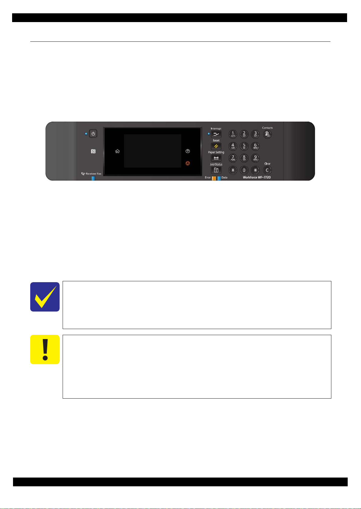
Epson WF-7720 / WF-7710 / WF-7210 Series Revision A
1.4 Service Support Mode
Overview
Service support mode is a service dedicated special mode that can be started by a special operation, and allows
you to execute functions including adjustment, inspection, and individual operation check functions.
Service Support Mode startup and operating procedures
WF-7720/7710 Series
1. Press the [#] and [Power SW] button until the screen switches, starting the printer.
2. Enter the ID.
ID to enter: 61544
Operating procedure
1.Push the [2] or [8] button until the value you wish to input is displayed.
2.Push the [6] button to check the value. The value will change to “*”, and await entry of the next digit.
3.Repeat steps 1 and 2 to enter the 5 digit ID.
4.When entry is completed, push the [#] button twice to confirm.
It is not possible to return to the previous digit after shifting digits. If you wish to correct
Please note that the execute button is not enabled until at least two digits have been
Solution if enter and execute the wrong ID
When a different mode starts:
When non-existent ID number:
Figure 1-5. Service Support Mode startup and operating procedures
the number of the previous digit, proceed with the steps until after step 5 and then perform input again.
entered.
If you enter the wrong ID and a different mode starts, there is the possibility of changing
important settings of the unit, so press the power button to turn off the power immediately and then perform the process again to enter the correct ID number.
The panel LCD display appears and the power is turned off automatically.
Appendix Fatal Error Code 29
Confidential
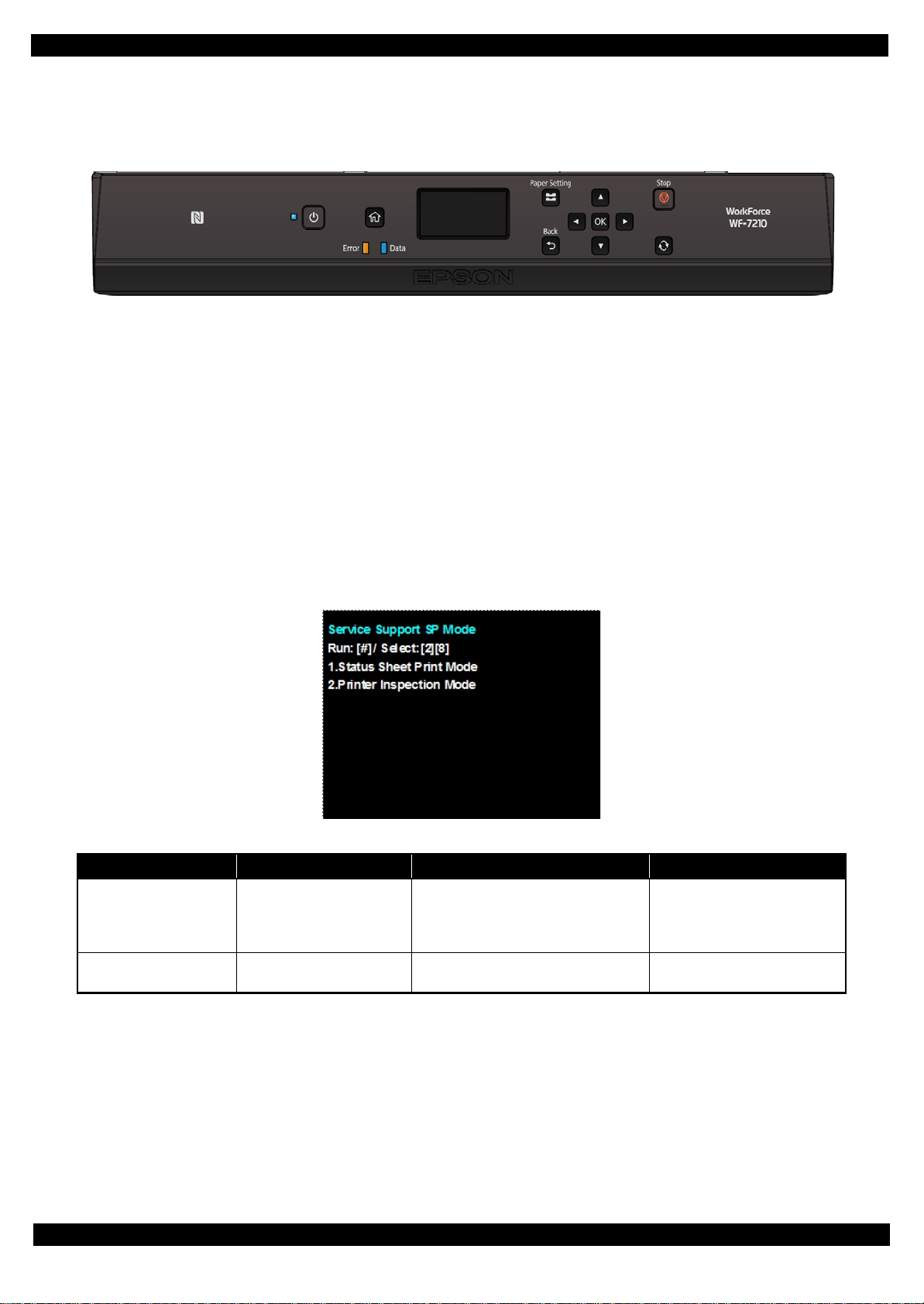
Epson WF-7720 / WF-7710 / WF-7210 Series Revision A
WF-7210 Series
1. Press the [OK] and [Power SW] button until the screen switches, starting the printer.
Figure 1-6. Service Support Mode startup and operating procedures
2. Enter the ID.
ID to enter: 61544
Operating procedure
1.Push the [2] or [8] button until the value you wish to input is displayed.
2.Push the [6] button to check the value. The value will change to “*”, and await entry of the next digit.
3.Repeat steps 1 and 2 to enter the 5 digit ID.
4.When entry is completed, push the [#] button twice to confirm.
Service Support Mode menu configuration
Figure 1-7. Se rvice Support Mode: Top Menu Screen
Item Display
Service status sheet print Status Sheet Print Mode
Printer mode Printer Inspection Mode
Overview Usage situation
In addition to checking confirming normal status sheet information, you can
also check information required for servicing.
With the ADF/SCN Unit removed, you
can carry out adjustment work.
Troubleshooting
Repair working
Appendix Fatal Error Code 30
Confidential
Loading...