


SERVICE MANUAL
Inverter Wall Mounted Single Split
MODELS |
|
FTXN25/35/50/60L |
RXN25/35/50/60L |
FTXN25/35/50/60M |
RXN25/35/50/60M |
FTXK25/35/50/60A |
RXK25/35/50/60A |
FTXN25/35/50/60N |
RXN25/35/50/60N |
FTXC25/35/50/60A |
RXC25/35/50/60A |
FTXB50/60A |
RXB50/60A |
FTXB50/60B |
RXB50/60B |
FTXB50/60C |
RXB50/60C |
ATXN25/35/50/60L |
ARXN25/35/50/60L |
ATXN25/35/50/60M |
ARXN25/35/50/60M |
ATXN25/35/50/60N |
ARXN25/35/50/60N |
ATXB50/60C |
ARXB50/60C |
SM-5WM-Y-EU-A3
Downloaded from www.Manualslib.com manuals search engine
Downloaded from www.Manualslib.com manuals search engine

|
|
|
Table of Contents |
Table of Contents |
|
||
1.0 Inverter Single Split...................................................................................................... |
1 |
||
1.1 |
Product line-up......................................................................................................... |
1 |
|
1.2 |
Printed Circuit board (PCB) connector wiring diagram............................................ |
4 |
|
1.3 |
Piping Length & Elevation...................................................................................... |
17 |
|
2.0 Function & Control...................................................................................................... |
18 |
||
2.1 Temperature Control............................................................................................... |
18 |
||
2.2 |
Cooling and Heating Mode Operation.................................................................... |
18 |
|
2.3 Fan Mode............................................................................................................... |
18 |
||
2.4 Auto Mode.............................................................................................................. |
19 |
||
2.5 |
Cold Draft Prevention............................................................................................. |
20 |
|
2.6 |
Sleep Mode............................................................................................................ |
20 |
|
2.7 |
Quiet Function........................................................................................................ |
21 |
|
2.8 Eco+ Function......................................................................................................... |
21 |
||
2.9 |
ID-OD Communication........................................................................................... |
21 |
|
2.10 Thermistors in RXN,RXB,RXC,ARXN,ARXB ...................................................... |
22 |
||
2.11 Minimum Off Time Control.................................................................................... |
22 |
||
2.12 |
Auto Restart........................................................................................................ |
22 |
|
2.13 Auto Random Restart........................................................................................... |
22 |
||
2.14 |
Four Way Valve Control....................................................................................... |
24 |
|
2.15 |
Outdoor Fan Control............................................................................................ |
24 |
|
2.16 |
Rotation Regulating Functions............................................................................. |
24 |
|
2.17 |
Defrost Cycle........................................................................................................ |
26 |
|
2.18 |
Indoor Coil Freeze Prevention............................................................................. |
26 |
|
2.19 |
High Pressure Protection..................................................................................... |
27 |
|
2.20 |
Discharge Pipe Temperature Control................................................................... |
27 |
|
2.21 |
Oil Recovery Control (Applicable for ARXN,RXN50/60L).................................... |
28 |
|
2.22 |
Overall Current Control........................................................................................ |
28 |
|
3.0 Service Diagnosis....................................................................................................... |
29 |
||
3.1 |
Error Indication from Indoor................................................................................... |
29 |
|
3.2 |
Error code retrieved by handset............................................................................. |
32 |
|
3.3 |
Error Indication from Outdoor................................................................................. |
34 |
|
3.4 |
Error code description for Inverter.......................................................................... |
36 |
|
Downloaded from www.Manualslib.com manuals search engine

|
|
Table of Contents |
4.0 |
Wiring Connection...................................................................................................... |
64 |
5.0 |
Refrigerant Diagram.................................................................................................... |
70 |
6.0 Appendix A................................................................................................................... |
72 |
|
ii
Downloaded from www.Manualslib.com manuals search engine
Table of Contents
Safety Cautions
Caution and warnings
•Be sure to read the following safety cautions before conducting repair work.
• Thecautionitemsareclassifiedinto“  Warning” and“
 Caution”. The“
 Warning” items are especially important since they can lead to death or serious injury if they are not followed closely. The “
 Caution” items can also lead to serious accidents under some conditions if they are not followed. Therefore, be sure to observe all the safety caution items described below.
•About the pictograms
 This symbol indicates an item for which caution must be exercised.
The pictogram shows the item to which attention must be paid.
 This symbol indicates a prohibited action.
The prohibited item or action is shown inside or near the symbol.
 This symbol indicates an action that must be taken, or an instruction.
The instruction is shown inside or near the symbol.
•After the repair work is complete, be sure to conduct a test operation to ensure that the equipment operates normally, and explain the cautions for operating the product to the customer.
Caution in Repair
 Warning
Be sure to disconnect the power cable plug from the plug socket before disassembling the equipment for a repair.
Working on the equipment that is connected to a power supply can cause an electrical shock.
If it is necessary to supply power to the equipment to conduct the repair or inspecting the circuits, do not touch any electrically charged sections of the equipment.
If the refrigerant gas discharges during the repair work, do not touch the discharging refrigerant gas.
The refrigerant gas can cause frostbite.
When disconnecting the suction or discharge pipe of the compressor at the welded section,releasetherefrigerantgascompletelyat a well-ventilatedplacefirst.
If there is a gas remaining inside the compressor, the refrigerant gas or refrigerating machine oil discharges when the pipe is disconnected, and it can cause injury.
If the refrigerant gas leaks during the repair work, ventilate the area. The refrigerant gas cangeneratetoxicgaseswhenit contactsflames.
The step-up capacitor supplies high-voltage electricity to the electrical components of the outdoor unit.
Be sure to discharge the capacitor completely before conducting repair work. A charged capacitor can cause an electrical shock.
Do not start or stop the air conditioner operation by plugging or unplugging the power cable plug.
Plugging or unplugging the power cable plug to operate the equipment can cause an electricalshockor fire.
Downloaded from www.Manualslib.com manuals search engine
Table of Contents
 Caution
Do not repair the electrical components with wet hands.
Working on the equipment with wet hands can cause an electrical shock.
Do not clean the air conditioner by splashing water.
Washing the unit with water can cause an electrical shock.
Be sure to provide the grounding when repairing the equipment in a humid or wet place, to avoid electrical shocks.
Be sure to turn off the power switch and unplug the power cable when cleaning the equipment.
The internal fan rotates at a high speed, and cause injury.
Do not tilt the unit when removing it.
Thewaterinsidetheunitcanspillandwetthefurnitureandfloor.
Besureto checkthattherefrigeratingcyclesectionhascooleddownsufficientlybefore conducting repair work.
Working on the unit when the refrigerating cycle section is hot can cause burns.
Use the welder in a well-ventilated place.
Usingthewelderin anenclosedroomcancauseoxygendeficiency.
iv
Downloaded from www.Manualslib.com manuals search engine
Table of Contents
Cautions Regarding Products after Repair
 Warning
Be sure to use parts listed in the service parts list of the applicable model and appropriate |
|
tools to conduct repair work. Never attempt to modify the equipment. |
|
The use of inappropriate parts or tools can cause an electrical shock, excessive heat |
|
generationor fire. |
|
Whenrelocatingtheequipment,makesurethatthenewinstallationsitehassufficient |
|
strength to withstand the weight of the equipment. |
|
If theinstallationsitedoesnothavesufficientstrengthandif theinstallationworkis not |
|
conducted securely, the equipment can fall and cause injury. |
|
|
|
Be sure to install the product correctly by using the provided standard installation frame. |
For integral |
Incorrect use of the installation frame and improper installation can cause the equipment |
units only |
to fall, resulting in injury. |
|
Be sure to install the product securely in the installation frame mounted on a window |
For integral |
frame. |
units only |
If the unit is not securely mounted, it can fall and cause injury. |
|
|
|
Be sure to use an exclusive power circuit for the equipment, and follow the technical |
|
standards related to the electrical equipment, the internal wiring regulations and the |
|
instruction manual for installation when conducting electrical work. |
|
Insufficientpowercircuitcapacityandimproperelectricalworkcancauseanelectrical |
|
shockor fire. |
|
Besureto usethespecifiedcableto connectbetweentheindoorandoutdoorunits.Make |
|
the connections securely and route the cable properly so that there is no force pulling the |
|
cable at the connection terminals. |
|
Improperconnectionscancauseexcessiveheatgenerationor fire. |
|
|
|
When connecting the cable between the indoor and outdoor units, make sure that the |
|
terminal cover does not lift off or dismount because of the cable. |
|
If the cover is not mounted properly, the terminal connection section can cause an |
|
electricalshock,excessiveheatgenerationor fire. |
|
Do not damage or modify the power cable. |
|
Damagedor modifiedpowercablecancauseanelectricalshockor fire. |
|
Placing heavy items on the power cable, and heating or pulling the power cable can |
|
damage the cable. |
|
|
|
Donotmixairor gasotherthanthespecifiedrefrigerant(R-410A)in therefrigerant |
|
system. |
|
If air enters the refrigerating system, an excessively high pressure results, causing |
|
equipment damage and injury. |
|
If the refrigerant gas leaks, be sure to locate the leak and repair it before charging the |
|
refrigerant. After charging refrigerant, make sure that there is no refrigerant leak. |
|
If the leak cannot be located and the repair work must be stopped, be sure to perform |
|
pump-down and close the service valve, to prevent the refrigerant gas from leaking into |
|
the room. The refrigerant gas itself is harmless, but it can generate toxic gases when it |
|
contactsflames,suchasfanandotherheaters,stovesandranges. |
|
|
|
When replacing the coin battery in the remote controller, be sure to disposed of the old |
|
battery to prevent children from swallowing it. |
|
If a child swallows the coin battery, see a doctor immediately. |
|
Downloaded from www.Manualslib.com manuals search engine
Table of Contents
 Caution
Installation of a leakage breaker is necessary in some cases depending on the conditions of the installation site, to prevent electrical shocks.
Do not install the equipment in a place where there is a possibility of combustible gas leaks.
If a combustiblegasleaksandremainsaroundtheunit,it cancausea fire.
Be sure to install the packing and seal on the installation frame properly.
If the packing and seal are not installed properly, water can enter the room and wet the furnitureandfloor.
Inspection after Repair
 Warning
Check to make sure that the power cable plug is not dirty or loose, then insert the plug into a power outlet all the way.
If theplughasdustor looseconnection,it cancauseanelectricalshockor fire.
If the power cable and lead wires have scratches or deteriorated, be sure to replace them.
Damagedcableandwirescancauseanelectricalshock,excessiveheatgenerationor fire.
Do not use a joined power cable or extension cable, or share the same power outlet with other electrical appliances, since it can cause an electrical shock, excessive heat generationor fire.
 Caution
Check to see if the parts and wires are mounted and connected properly, and if the connections at the soldered or crimped terminals are secure.
Improperinstallationandconnectionscancauseexcessiveheatgeneration,fireor an electrical shock.
If the installation platform or frame has corroded, replace it.
Corroded installation platform or frame can cause the unit to fall, resulting in injury.
Check the grounding, and repair it if the equipment is not properly grounded. Improper grounding can cause an electrical shock.
Be sure to measure the insulation resistance after the repair, and make sure that the resistance is 1 Mohm or higher.
Faulty insulation can cause an electrical shock.
Be sure to check the drainage of the indoor unit after the repair.
Faultydrainagecancausethewaterto entertheroomandwetthefurnitureandfloor.
vi
Downloaded from www.Manualslib.com manuals search engine

Inverter Single Split
1.0Inverter Single Split
1.1Product line-up
1.1.1 Indoor Unit
|
|
|
|
|
|
|
|
|
Classification |
|
|
|
|
|
||||
|
|
Handset |
|
|
PCB |
|
|
|
|
AirPurification |
|
|
Marking |
|
Others |
|||
Nomenclature |
|
|
|
|
|
|
|
|
|
|
|
|
|
|
|
|
|
|
BRC52A61 |
|
BRC52B63 |
W 2 03C |
W 2 03D |
W 2 03E |
|
W 2 03E M |
|
W 2 04A |
W 2 04B |
Saranet Filter |
|
Titanium Apatite |
CE |
GOST |
EAC |
Auto Restart |
|
|
|
|
|
|
||||||||||||||
|
|
|
|
|
|
|
|
|
|
|
|
|
|
|
|
|
|
|
FTXN25/35LV1B |
X |
|
|
X |
|
|
|
|
|
|
|
X |
|
X |
X |
X |
|
X |
|
|
|
|
|
|
|
|
|
|
|
|
|
|
|
|
|
|
|
FTXN50/60LV1B |
X |
|
|
|
|
|
|
|
|
X |
|
X |
|
X |
X |
X |
|
X |
|
|
|
|
|
|
|
|
|
|
|
|
|
|
|
|
|
|
|
ATXN25/35LV1B |
X |
|
|
X |
|
|
|
|
|
|
|
X |
|
|
X |
|
|
X |
|
|
|
|
|
|
|
|
|
|
|
|
|
|
|
|
|
|
|
ATXN50/60LV1B |
X |
|
|
|
|
|
|
|
|
X |
|
X |
|
|
X |
|
|
X |
|
|
|
|
|
|
|
|
|
|
|
|
|
|
|
|
|
|
|
FTXB50/60AV1B |
X |
|
|
|
|
|
|
|
|
X |
|
X |
|
|
X |
|
|
X |
|
|
|
|
|
|
|
|
|
|
|
|
|
|
|
|
|
|
|
FTXB50/60BV1B |
X |
|
|
|
|
|
|
|
|
X |
|
X |
|
|
X |
|
|
X |
|
|
|
|
|
|
|
|
|
|
|
|
|
|
|
|
|
|
|
FTXN25/35MV1 |
X |
|
|
X |
|
|
|
|
|
|
|
X |
|
X |
X |
X |
|
X |
|
|
|
|
|
|
|
|
|
|
|
|
|
|
|
|
|
|
|
FTXN50/60MV1 |
X |
|
|
|
|
|
|
|
|
X |
|
X |
|
X |
X |
X |
|
X |
|
|
|
|
|
|
|
|
|
|
|
|
|
|
|
|
|
|
|
FTXN25/35MV1B |
X |
|
|
|
X |
|
|
|
|
|
|
X |
|
X |
X |
|
X |
X |
|
|
|
|
|
|
|
|
|
|
|
|
|
|
|
|
|
|
|
FTXN50/60MV1B |
X |
|
|
|
|
|
|
|
|
X |
|
X |
|
X |
X |
|
X |
X |
|
|
|
|
|
|
|
|
|
|
|
|
|
|
|
|
|
|
|
FTXN25/35MV1B9 |
X |
|
|
X |
|
|
|
|
|
|
|
X |
|
|
X |
|
|
X |
|
|
|
|
|
|
|
|
|
|
|
|
|
|
|
|
|
|
|
FTXN50/60MV1B9 |
X |
|
|
|
|
|
|
|
|
X |
|
X |
|
|
X |
|
|
X |
|
|
|
|
|
|
|
|
|
|
|
|
|
|
|
|
|
|
|
ATXN25/35MV1B |
X |
|
|
X |
|
|
|
|
|
|
|
X |
|
|
X |
|
|
X |
|
|
|
|
|
|
|
|
|
|
|
|
|
|
|
|
|
|
|
ATXN50/60MV1B |
X |
|
|
|
|
|
|
|
|
X |
|
X |
|
|
X |
|
|
X |
|
|
|
|
|
|
|
|
|
|
|
|
|
|
|
|
|
|
|
ATXN25/35MV1B7 |
X |
|
|
X |
|
|
|
|
|
|
|
X |
|
|
X |
|
X |
X |
|
|
|
|
|
|
|
|
|
|
|
|
|
|
|
|
|
|
|
ATXN50/60MV1B7 |
X |
|
|
|
|
|
|
|
|
X |
|
X |
|
|
X |
|
X |
X |
|
|
|
|
|
|
|
|
|
|
|
|
|
|
|
|
|
|
|
ATXN25/35MV16 |
X |
|
|
|
X |
|
|
|
|
|
|
X |
|
X |
|
|
X |
X |
|
|
|
|
|
|
|
|
|
|
|
|
|
|
|
|
|
|
|
ATXN50/60MV16 |
X |
|
|
|
|
|
|
|
|
X |
|
X |
|
X |
|
|
X |
X |
|
|
|
|
|
|
|
|
|
|
|
|
|
|
|
|
|
|
|
FTXK25/35AV1BW |
|
|
X |
|
|
|
|
X |
|
|
|
X |
|
|
X |
|
X |
X |
|
|
|
|
|
|
|
|
|
|
|
|
|
|
|
|
|
|
|
FTXK50/60AV1BW |
|
|
X |
|
|
|
|
|
|
|
X |
X |
|
|
X |
|
X |
X |
|
|
|
|
|
|
|
|
|
|
|
|
|
|
|
|
|
|
|
FTXK25/35AV1BS |
|
|
X |
|
|
|
|
X |
|
|
|
X |
|
|
X |
|
X |
X |
|
|
|
|
|
|
|
|
|
|
|
|
|
|
|
|
|
|
|
FTXK50/60AV1BS |
|
|
X |
|
|
|
|
|
|
|
X |
X |
|
|
X |
|
X |
X |
|
|
|
|
|
|
|
|
|
|
|
|
|
|
|
|
|
|
|
FTXN25/35NV1B |
X |
|
|
|
|
X |
|
|
|
|
|
X |
|
X |
X |
|
|
X |
|
|
|
|
|
|
|
|
|
|
|
|
|
|
|
|
|
|
|
FTXN50/60NV1B |
X |
|
|
|
|
|
|
|
|
|
X |
X |
|
X |
X |
|
|
X |
|
|
|
|
|
|
|
|
|
|
|
|
|
|
|
|
|
|
|
1
Downloaded from www.Manualslib.com manuals search engine

Inverter Single Split
1.1.1 Indoor Unit
|
|
|
|
|
|
|
|
|
Classification |
|
|
|
|
|
|||
|
|
Handset |
|
|
|
PCB |
|
|
|
|
AirPurification |
|
Marking |
|
Others |
||
Nomenclature |
|
|
|
|
|
|
|
|
|
|
|
|
|
|
|
|
|
BRC52A61 |
|
BRC52B63 |
W 2 03C |
W 2 03D |
W 2 03E |
|
W 2 03E M |
|
W 2 04A |
W 2 04B |
Saranet Filter |
Titanium Apatite |
CE |
GOST |
EAC |
Auto Restart |
|
|
|
|
|
||||||||||||||
|
|
|
|
|
|
|
|
|
|
|
|
|
|
|
|
|
|
ATXN25/35NV1B |
X |
|
|
|
|
X |
|
|
|
|
|
X |
X |
X |
|
|
X |
|
|
|
|
|
|
|
|
|
|
|
|
|
|
|
|
|
|
ATXN50/60NV1B |
X |
|
|
|
|
|
|
|
|
|
X |
X |
X |
X |
|
|
X |
|
|
|
|
|
|
|
|
|
|
|
|
|
|
|
|
|
|
ATXN25/35NV1B9 |
X |
|
|
|
|
X |
|
|
|
|
|
X |
X |
X |
|
|
X |
|
|
|
|
|
|
|
|
|
|
|
|
|
|
|
|
|
|
ATXN50/60NV1B9 |
X |
|
|
|
|
|
|
|
|
|
X |
X |
X |
X |
|
|
X |
|
|
|
|
|
|
|
|
|
|
|
|
|
|
|
|
|
|
ATXN25/35NV1B7 |
X |
|
|
|
|
X |
|
|
|
|
|
X |
|
X |
|
|
X |
|
|
|
|
|
|
|
|
|
|
|
|
|
|
|
|
|
|
ATXN50/60NV1B7 |
X |
|
|
|
|
|
|
|
|
|
X |
X |
|
X |
|
|
X |
|
|
|
|
|
|
|
|
|
|
|
|
|
|
|
|
|
|
FTXB50/60CV1B |
X |
|
|
|
|
|
|
|
|
X |
|
X |
X |
X |
|
X |
X |
|
|
|
|
|
|
|
|
|
|
|
|
|
|
|
|
|
|
ATXB50/60CV1B |
X |
|
|
|
|
|
|
|
|
X |
|
X |
X |
X |
|
|
X |
|
|
|
|
|
|
|
|
|
|
|
|
|
|
|
|
|
|
FTXC25/35AV1B |
X |
|
|
|
|
X |
|
|
|
|
|
X |
X |
X |
|
|
X |
|
|
|
|
|
|
|
|
|
|
|
|
|
|
|
|
|
|
FTXC50/60AV1B |
X |
|
|
|
|
|
|
|
|
|
X |
X |
X |
X |
|
|
X |
|
|
|
|
|
|
|
|
|
|
|
|
|
|
|
|
|
|
2
Downloaded from www.Manualslib.com manuals search engine
Inverter Single Split
1.1.2 Outdoor Unit
|
|
|
|
|
|
|
Classification |
|
|
|
|
||
|
|
PCB |
Refrigerant Control |
|
Fin |
Compressor |
|
|
Marking |
|
Others |
||
Nomenclature |
|
|
|
|
|
|
|
|
|
|
|
|
|
OYL Board |
|
DKR Board |
EXV |
Hydrophilic (Blue) |
|
Hydrophilic (Gold) |
DC Inverter Swing |
|
CE |
GOST |
EAC |
Drain Elbow |
|
|
|
|
|
||||||||||
|
|
|
|
|
|
|
|
|
|
|
|
|
|
RXN25/35LV1B9 |
|
|
X |
X |
X |
|
|
X |
|
X |
X |
|
X |
RXN50/60LV1B9 |
X |
|
|
X |
X |
|
|
X |
|
X |
X |
|
X |
ARXN25/35LV1B |
|
|
X |
X |
|
|
X |
X |
|
X |
|
|
X |
|
|
|
|
|
|
|
|
|
|
|
|
|
|
ARXN50/60LV1B |
X |
|
|
X |
|
|
X |
X |
|
X |
|
|
X |
RXB50/60AV1B |
X |
|
|
X |
X |
|
|
X |
|
X |
|
|
X |
RXB50/60BV1B |
|
|
X |
X |
X |
|
|
X |
|
X |
|
|
X |
|
|
|
|
|
|
|
|
|
|
|
|
|
|
RXN25/35MV1 |
|
|
X |
X |
X |
|
|
X |
|
X |
X |
|
X |
RXN50/60MV1 |
|
|
X |
X |
X |
|
|
X |
|
X |
X |
|
X |
RXN25/35MV1B |
|
|
X |
X |
X |
|
|
X |
|
X |
|
X |
X |
|
|
|
|
|
|
|
|
|
|
|
|
|
|
RXN50/60MV1B |
|
|
X |
X |
X |
|
|
X |
|
X |
|
X |
X |
RXN25/35MV1B9 |
|
|
X |
X |
X |
|
|
X |
|
X |
|
|
X |
RXN50/60MV1B9 |
|
|
X |
X |
X |
|
|
X |
|
X |
|
|
X |
|
|
|
|
|
|
|
|
|
|
|
|
|
|
ARXN25/35MV1B |
|
|
X |
X |
|
|
X |
X |
|
X |
|
|
X |
ARXN50/60MV1B |
|
|
X |
X |
|
|
X |
X |
|
X |
|
|
X |
ARXN25/35MV1B7 |
|
|
X |
X |
|
|
X |
X |
|
X |
|
X |
X |
|
|
|
|
|
|
|
|
|
|
|
|
|
|
ARXN50/60MV1B7 |
|
|
X |
X |
|
|
X |
X |
|
X |
|
X |
X |
ARXN25/35MV16 |
|
|
X |
X |
|
|
X |
X |
|
|
|
X |
X |
ARXN50/60MV16 |
|
|
X |
X |
|
|
X |
X |
|
|
|
X |
X |
|
|
|
|
|
|
|
|
|
|
|
|
|
|
RXK25/35AV1B |
|
|
X |
X |
X |
|
|
X |
|
X |
|
X |
X |
RXK50/60AV1B |
|
|
X |
X |
X |
|
|
X |
|
X |
|
X |
X |
RXN25/35NV1B |
|
|
X |
X |
X |
|
|
X |
|
X |
|
|
X |
|
|
|
|
|
|
|
|
|
|
|
|
|
|
RXN50/60NV1B |
|
|
X |
X |
X |
|
|
X |
|
X |
|
|
X |
ARXN25/35NV1B |
|
|
X |
X |
X |
|
|
X |
|
X |
|
|
X |
ARXN50/60NV1B |
|
|
X |
X |
X |
|
|
X |
|
X |
|
|
X |
|
|
|
|
|
|
|
|
|
|
|
|
|
|
ARXN25/35NV1B9 |
|
|
X |
X |
X |
|
|
X |
|
X |
|
|
X |
ARXN50/60NV1B9 |
|
|
X |
X |
X |
|
|
X |
|
X |
|
|
X |
RXB50/60CV1B |
|
|
X |
X |
X |
|
|
X |
|
X |
|
X |
X |
|
|
|
|
|
|
|
|
|
|
|
|
|
|
ARXB50/60CV1B |
|
|
X |
X |
X |
|
|
X |
|
X |
|
|
X |
RXC25/35AV1B |
|
|
X |
X |
X |
|
|
X |
|
X |
|
|
X |
RXC50/60AV1B |
|
|
X |
X |
X |
|
|
X |
|
X |
|
|
X |
|
|
|
|
|
|
|
|
|
|
|
|
|
|
3
Downloaded from www.Manualslib.com manuals search engine
Inverter Single Split
1.2 Printed Circuit board (PCB) connector wiring diagram
1.2.1 Indoor PCB: FTXN25/35L, FTXN25/35MV1, FTXN25/35MV1B9, ATXN25/35L, ATXN25/35MV1B, ATXN25/35MV1B7
1.2.1.1 Main PCB: W_2_03C
Item |
Indication on PCB |
Description |
|
|
|
1 |
A1 |
Connector for fan motor |
|
|
|
2 |
A2 |
Connector for swing motor |
|
|
|
3 |
A3 |
Connector for fan motor feedback |
|
|
|
4 |
A4 |
Fuse |
|
|
|
5 |
A5 |
Varistor |
|
|
|
6 |
A6 |
Connector for wired handset |
|
|
|
7 |
A7 |
Connector for signal receiver PCB |
|
|
|
8 |
A8 |
Connector for heat exchanger thermistor |
|
|
|
A1 |
A2 |
A3 |
A4
A5
A6
A7
A8
4
Downloaded from www.Manualslib.com manuals search engine
Inverter Single Split
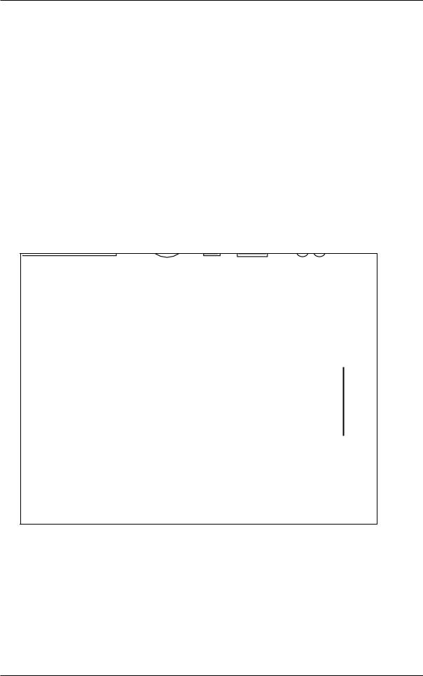
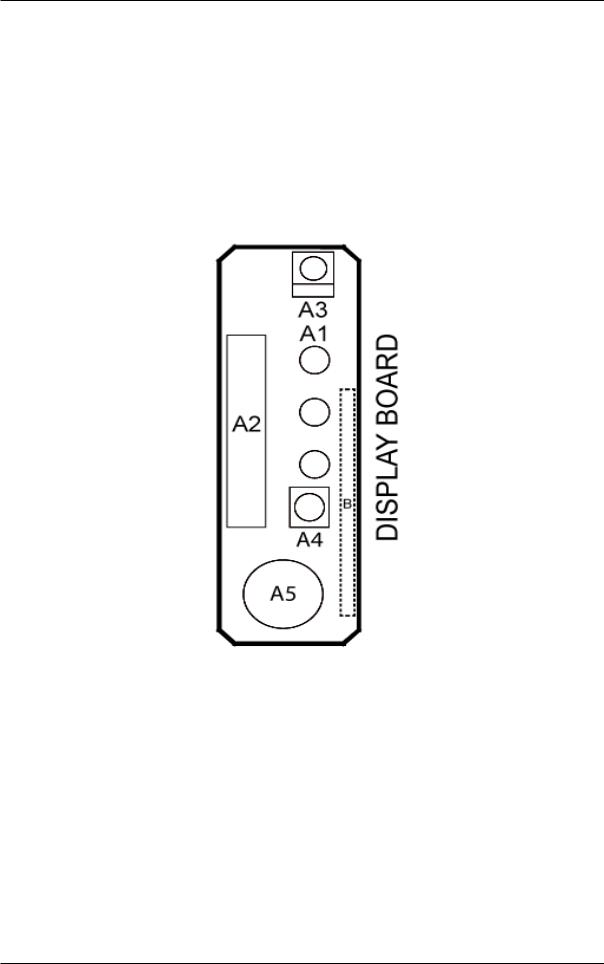
1.2.1.2 Signal board
Item |
Indication on PCB |
Description |
|
|
|
1 |
A1 |
Operational LED |
|
|
|
2 |
A2 |
Connector for Control PCB |
|
|
|
3 |
A3 |
Handset signal receiver |
|
|
|
4 |
A4 |
Operation ON/OFF switch |
|
|
|
5 |
A5 |
Buzzer |
|
|
|
Applicable Model :
FTXN25/35L, FTXN25/35MV1, FTXN25/35MV1B9,
ATXN25/35L, ATXN25/35MV1B, ATXN25/35MV1B7
5
Downloaded from www.Manualslib.com manuals search engine
Inverter Single Split
1.2.2 Indoor PCB: FTXN25/35MV1B, FTXN25/35N, FTXK25/35A, FTXC25/35A,
ATXN25/35MV16, ATXN25/35N
1.2.2.1 Main PCB: W_2_03D ; W_2_03E ; W_2_03E_M
Item |
Indication on PCB |
Description |
|
|
|
1 |
A1 |
Connector for fan motor |
|
|
|
2 |
A2 |
Connector for swing motor |
|
|
|
3 |
A3 |
Connector for fan motor feedback |
|
|
|
4 |
A4 |
Fuse |
|
|
|
5 |
A5 |
Varistor |
|
|
|
6 |
A6 |
Connector for wired handset |
|
|
|
7 |
A7 |
Connector for signal receiver PCB |
|
|
|
8 |
A8 |
Connector for heat exchanger thermistor |
|
|
|
A1 A2 A3
A5 |
A4 |
|
A7
A6
A8
6
Downloaded from www.Manualslib.com manuals search engine
Inverter Single Split
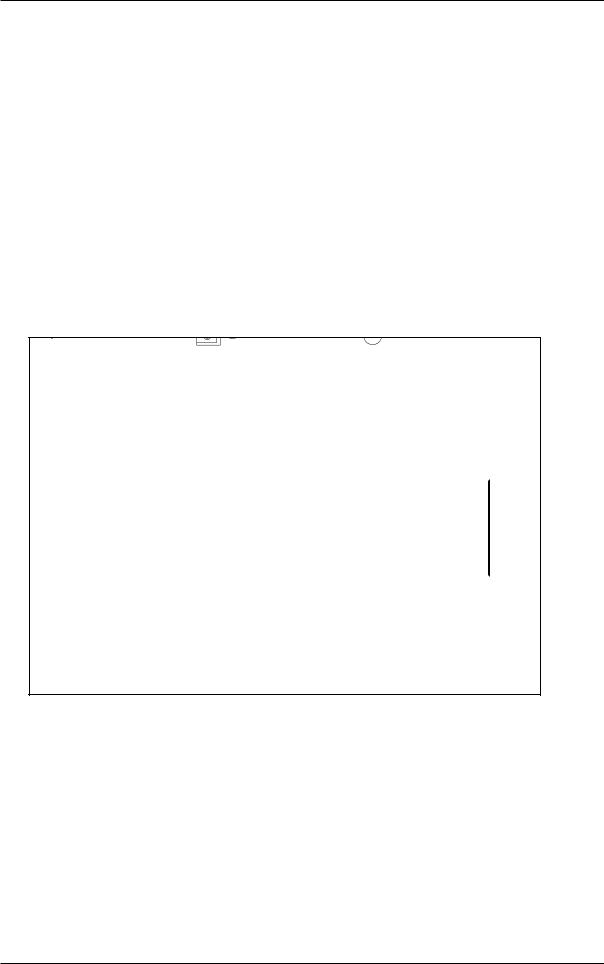
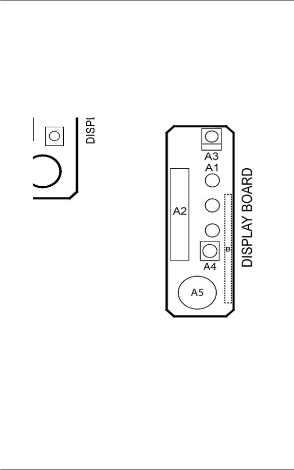
1.2.2.2 Signal board
Item |
Indication on PCB |
Description |
|
|
|
1 |
A1 |
Operational LED |
|
|
|
2 |
A2 |
Connector for Control PCB |
|
|
|
3 |
A3 |
Handset signal receiver |
|
|
|
4 |
A4 |
Operation ON/OFF switch |
|
|
|
5 |
A5 |
Buzzer |
|
|
|
A1
A3
A2
A4
A5
Applicable Model : |
Applicable Model : |
FTXK25/35A |
FTXN25/35MV1B, FTXN25/35N, |
|
FTXC25/35A, ATXN25/35MV16, |
|
ATXN25/35N |
7
Downloaded from www.Manualslib.com manuals search engine
Inverter Single Split
1.2.3 Indoor PCB: FTXB50/60A, FTXB50/60B, FTXB50/60C, FTXN50/60L, FTXN50/60M,
FTXN50/60N, FTXK50/60A, FTXC50/60A, ATXB50/60C, ATXN50/60L,
ATXN50/60M, ATXN50/60N
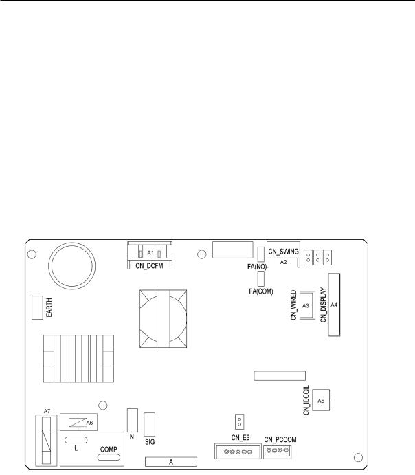
1.2.3.1 Main PCB: W_2_04A ; W_2_04B
|
|
Item |
Indication on PCB |
Description |
|
|||
|
|
|
|
|
|
|
|
|
|
1 |
A1 |
Connector for fan motor |
|
||||
|
|
|
|
|
|
|
|
|
|
2 |
A2 |
Connector for swing motor |
|
||||
|
|
|
|
|
|
|
|
|
|
3 |
A3 |
Connector for fan motor feedback |
|
||||
|
|
|
|
|
|
|
|
|
|
4 |
A4 |
Fuse |
|
||||
|
|
|
|
|
|
|
|
|
|
5 |
A5 |
Varistor |
|
||||
|
|
|
|
|
|
|
|
|
|
6 |
A6 |
Connector for wired handset |
|
||||
|
|
|
|
|
|
|
|
|
|
7 |
A7 |
Connector for signal receiver PCB |
|
||||
|
|
|
|
|
|
|
|
|
|
|
|
|
|
|
|
|
|
|
|
|
|
|
|
|
|
|
|
|
|
|
|
|
|
|
|
|
|
|
|
|
|
|
|
|
|
|
|
|
|
|
|
|
|
|
|
|
|
|
|
|
|
|
|
|
|
|
|
|
|
|
|
|
|
|
|
|
|
|
|
|
|
|
|
|
|
|
|
|
|
|
|
|
|
|
|
|
|
|
8
Downloaded from www.Manualslib.com manuals search engine
Inverter Single Split
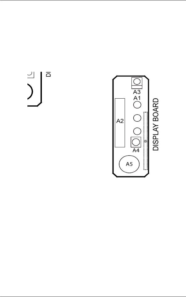
1.2.3.2 Signal board
Item |
Indication on PCB |
Description |
|
|
|
1 |
A1 |
Operational LED |
|
|
|
2 |
A2 |
Connector for Control PCB |
|
|
|
3 |
A3 |
Handset signal receiver |
|
|
|
4 |
A4 |
Operation ON/OFF switch |
|
|
|
5 |
A5 |
Buzzer |
|
|
|
A1
A3
A2
A4
A5
Applicable Model : |
Applicable Model : |
FTXK50/60A |
FTXB50/60A, FTXB50/60B, FTXB50/60C, |
|
FTXN50/60L, FTXN50/60M, FTXN50/60N, |
|
FTXC50/60A |
|
ATXB50/60C, ATXN50/60L, ATXN50/60M, |
|
ATXN50/60N |
9
Downloaded from www.Manualslib.com manuals search engine
Inverter Single Split
1.2.4 Outdoor PCB: RXN25/35N, RXK25/35A, RXC25/35A, ARXN25/35MV1B7,
ARXN25/35MV16, ARXN25/35N
1.2.4.1 Main PCB
Item |
Indication on PCB |
Description |
|
|
|
1 |
S11 |
Connector for S10 on main PCB |
|
|
|
2 |
HL1, HN1, S |
Connector for terminal board |
|
|
|
3 |
E1, E2 |
Terminal for earth wire |
|
|
|
4 |
HL2, HN2 |
Connector for HL3 HN3 on main PCB |
|
|
|
5 |
HL4, HN4 |
Connector for S12 on main PCB |
|
|
|
6 |
FU1 |
Fuse (3.15A, 250V) |
|
|
|
7 |
FU3 |
Fuse (30A, 250V) |
|
|
|
8 |
V2, V3 |
Varistor |
|
|
|
10
Downloaded from www.Manualslib.com manuals search engine
Inverter Single Split
1.2.5 Outdoor PCB: RXN25/35L, RXN25/35MV1, RXN25/35MV1B, RXN25/35MV1B9,
ARXN25/35L, ARXN25/35MV1B
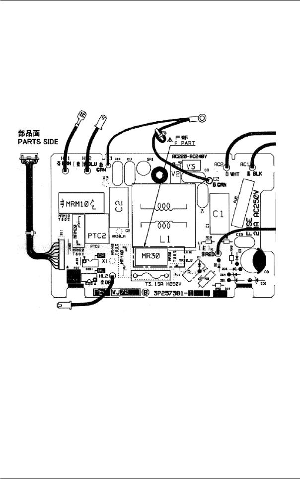
1.2.5.1 Filter PCB
Item |
Indication on PCB |
Description |
|
|
|
1 |
S11 |
Connector for indoor PCB |
|
|
|
2 |
FU3 |
Fuse (20A) |
|
|
|
3 |
V2, V3 |
Varistor |
|
|
|
11
Downloaded from www.Manualslib.com manuals search engine

Inverter Single Split
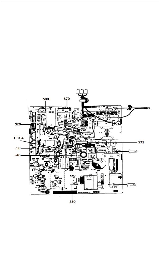
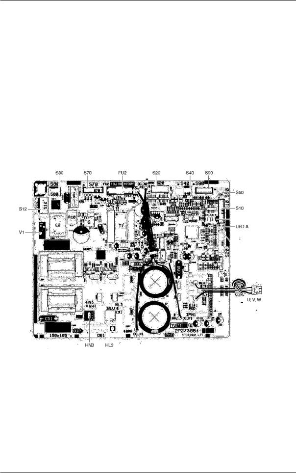
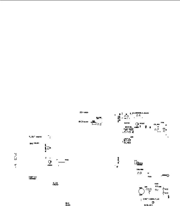
1.2.5.2 Main PCB
Item |
Indication on PCB |
Description |
|
|
|
|
|
1 |
S10 |
ConnectorforfilterPCB |
|
|
|
|
|
2 |
S20 |
Connector for electronic expansion valve coil |
|
|
|
|
|
3 |
S40 |
Connector for overload protector |
|
|
|
|
|
4 |
S70 |
Connector for fan motor |
|
|
|
|
|
5 |
S80 |
Connector for four way valve coil |
|
|
|
|
|
6 |
S90 |
Connector for thermistors (outdoor temperature, |
|
outdoor heat exchanger, discharge pipe) |
|||
|
|
||
7 |
HL3, HN3 |
ConnectorforfilterPCB |
|
|
|
|
|
8 |
FU1, FU2 |
Fuse (3.15A) |
|
|
|
|
|
9 |
LED A |
Service monitor LED (green) |
|
|
|
|
|
10 |
V1 |
Varistor |
|
|
|
|
12
Downloaded from www.Manualslib.com manuals search engine
Inverter Single Split
1.2.6 Outdoor PCB: RXB50/60B, RXB50/60C, RXN50/60M, RXN50/60N, RXK50/60A,
RXC50/60A, ARXB50/60C, ARXN50/60M, ARXN50/60N
1.2.6.1 Filter PCB
Item |
Indication on PCB |
Description |
|
|
|
1 |
S11 |
Connector for indoor PCB |
|
|
|
2 |
FU3 |
Fuse (20A) |
|
|
|
3 |
V2, V3 |
Varistor |
|
|
|
13
Downloaded from www.Manualslib.com manuals search engine
Inverter Single Split
1.2.6.2 Main PCB
Item |
Indication on PCB |
Description |
|
|
|
|
|
1 |
S10 |
ConnectorforfilterPCB |
|
|
|
|
|
2 |
S20 |
Connector for electronic expansion valve coil |
|
|
|
|
|
3 |
S40 |
Connector for overload protector |
|
|
|
|
|
4 |
S70 |
Connector for fan motor |
|
|
|
|
|
5 |
S80 |
Connector for four way valve coil |
|
|
|
|
|
6 |
S90 |
Connector for thermistors (outdoor temperature, |
|
outdoor heat exchanger, discharge pipe) |
|||
|
|
||
7 |
HL3, HN3 |
ConnectorforfilterPCB |
|
|
|
|
|
8 |
FU1, FU2 |
Fuse (3.15A) |
|
|
|
|
|
9 |
LED A |
Service monitor LED (green) |
|
|
|
|
|
10 |
V1 |
Varistor |
|
|
|
|
14
Downloaded from www.Manualslib.com manuals search engine
Inverter Single Split
1.2.7 Outdoor PCB: RXB50/60A, RXN50/60L, ARXN50/60L
1.2.7.1 Main PCB
|
|
Item |
Indication on PCB |
Description |
|
||||||||||||||||||||||||||||||||||||||||||||||||||||||||||||||||||||||||||||||||||||||||||||
|
|
|
|
|
|
|
|
|
|
|
|
|
|
|
|
|
|
|
|
|
|
|
|
|
|
|
|
|
|
|
|
|
|
|
|
|
|
|
|
|
|
|
|
|
|
|
|
|
|
|
|
|
|
|
|
|
|
|
|
|
|
|
|
|
|
|
|
|
|
|
|
|
|
|
|
|
|
|
|
|
|
|
|
|
|
|
|
|
|
|
|
|
|
|
|
|
|
|
1 |
|
|
|
|
|
|
|
|
A1 |
Connector for IPM PCB |
|
|||||||||||||||||||||||||||||||||||||||||||||||||||||||||||||||||||||||||||||||||||||
|
|
|
|
|
|
|
|
|
|
|
|
|
|
|
|
|
|
|
|
|
|
|
|
|
|
|
|
|
|
|
|
|
|
|
|
|
|
|
|
|
|
|
|
|
|
|
|
|
|
|
|
|
|
|
|
|
|
|
|
|
|
|
|
|
|
|
|
|
|
|
|
|
|
|
|
|
|
|
|
|
|
|
|
|
|
|
|
|
|
|
|
|
|
|
|
|
|
|
2 |
|
|
|
|
|
|
|
|
A2 |
Connector for heat sink thermistor |
|
|||||||||||||||||||||||||||||||||||||||||||||||||||||||||||||||||||||||||||||||||||||
|
|
|
|
|
|
|
|
|
|
|
|
|
|
|
|
|
|
|
|
|
|
|
|
|
|
|
|
|
|
|
|
|
|
|
|
|
|
|
|
|
|
|
|
|
|
|
|
|
|
|
|
|
|
|
|
|
|
|
|
|
|
|
|
|
|
|
|
|
|
|
|
|
|
|
|
|
|
|
|
|
|
|
|
|
|
|
|
|
|
|
|
|
|
|
|
|
|
|
3 |
|
|
|
|
|
|
|
|
A3 |
Connector for thermistors (outdoor air, heat exchanger, |
|
|||||||||||||||||||||||||||||||||||||||||||||||||||||||||||||||||||||||||||||||||||||
|
|
|
|
|
|
|
|
|
discharge pipe) |
|
|||||||||||||||||||||||||||||||||||||||||||||||||||||||||||||||||||||||||||||||||||||||
|
|
|
|
|
|
|
|
|
|
|
|
|
|
|
|
|
|
|
|
|
|
|
|
|
|
|
|
|
|
|
|
|
|||||||||||||||||||||||||||||||||||||||||||||||||||||||||||||||||
|
4 |
|
|
|
|
|
|
|
|
A4 |
Connector for electronic expansion valve coil |
|
|||||||||||||||||||||||||||||||||||||||||||||||||||||||||||||||||||||||||||||||||||||
|
|
|
|
|
|
|
|
|
|
|
|
|
|
|
|
|
|
|
|
|
|
|
|
|
|
|
|
|
|
|
|
|
|
|
|
|
|
|
|
|
|
|
|
|
|
|
|
|
|
|
|
|
|
|
|
|
|
|
|
|
|
|
|
|
|
|
|
|
|
|
|
|
|
|
|
|
|
|
|
|
|
|
|
|
|
|
|
|
|
|
|
|
|
|
|
|
|
|
5 |
|
|
|
|
|
|
|
|
A5, A6 |
Connector for display PCB |
|
|||||||||||||||||||||||||||||||||||||||||||||||||||||||||||||||||||||||||||||||||||||
|
|
|
|
|
|
|
|
|
|
|
|
|
|
|
|
|
|
|
|
|
|
|
|
|
|
|
|
|
|
|
|
|
|
|
|
|
|
|
|
|
|
|
|
|
|
|
|
|
|
|
|
|
|
|
|
|
|
|
|
|
|
|
|
|
|
|
|
|
|
|
|
|
|
|
|
|
|
|
|
|
|
|
|
|
|
|
|
|
|
|
|
|
|
|
|
|
|
|
6 |
|
|
|
|
|
|
|
|
A7 |
Connector for four way valve coil |
|
|||||||||||||||||||||||||||||||||||||||||||||||||||||||||||||||||||||||||||||||||||||
|
|
|
|
|
|
|
|
|
|
|
|
|
|
|
|
|
|
|
|
|
|
|
|
|
|
|
|
|
|
|
|
|
|
|
|
|
|
|
|
|
|
|
|
|
|
|
|
|
|
|
|
|
|
|
|
|
|
|
|
|
|
|
|
|
|
|
|
|
|
|
|
|
|
|
|
|
|
|
|
|
|
|
|
|
|
|
|
|
|
|
|
|
|
|
|
|
|
|
7 |
|
|
|
|
|
|
|
|
A8 |
Connector for fan motor |
|
|||||||||||||||||||||||||||||||||||||||||||||||||||||||||||||||||||||||||||||||||||||
|
|
|
|
|
|
|
|
|
|
|
|
|
|
|
|
|
|
|
|
|
|
|
|
|
|
|
|
|
|
|
|
|
|
|
|
|
|
|
|
|
|
|
|
|
|
|
|
|
|
|
|
|
|
|
|
|
|
|
|
|
|
|
|
|
|
|
|
|
|
|
|
|
|
|
|
|
|
|
|
|
|
|
|
|
|
|
|
|
|
|
|
|
|
|
|
|
|
|
8 |
|
|
|
|
|
|
|
|
A9 |
Fuse |
|
|||||||||||||||||||||||||||||||||||||||||||||||||||||||||||||||||||||||||||||||||||||
|
|
|
|
|
|
|
|
|
|
|
|
|
|
|
|
|
|
|
|
|
|
|
|
|
|
|
|
|
|
|
|
|
|
|
|
|
|
|
|
|
|
|
|
|
|
|
|
|
|
|
|
|
|
|
|
|
|
|
|
|
|
|
|
|
|
|
|
|
|
|
|
|
|
|
|
|
|
|
|
|
|
|
|
|
|
|
|
|
|
|
|
|
|
|
|
|
|
|
9 |
|
|
|
|
A10, A11, A12, A13 |
Varistor |
|
|||||||||||||||||||||||||||||||||||||||||||||||||||||||||||||||||||||||||||||||||||||||||
|
|
|
|
|
|
|
|
|
|
|
|
|
|
|
|
|
|
|
|
|
|
|
|
|
|
|
|
|
|
|
|
|
|
|
|
|
|
|
|
|
|
|
|
|
|
|
|
|
|
|
|
|
|
|
|
|
|
|
|
|
|
|
|
|
|
|
|
|
|
|
|
|
|
|
|
|
|
|
|
|
|
|
|
|
|
|
|
|
|
|
|
|
|
|
|
|
|
|
|
|
|
|
|
|
|
|
|
|
|
|
|
|
|
|
|
|
|
|
|
|
|
|
|
|
|
|
|
|
|
|
|
|
|
|
|
|
|
|
|
|
|
|
|
|
|
|
|
|
|
|
|
|
|
|
|
|
|
|
|
|
|
|
|
|
|
|
|
|
|
|
|
|
|
|
|
|
|
|
|
|
|
|
|
|
|
|
|
|
|
|
|
|
|
|
|
|
|
|
|
|
|
|
|
|
|
|
|
|
|
|
|
|
|
|
|
|
|
|
|
|
|
|
|
|
|
|
|
|
|
|
|
|
|
|
|
|
|
|
|
|
|
|
|
|
|
|
|
|
|
|
|
|
|
|
|
|
|
|
|
|
|
|
|
|
|
|
|
|
|
|
|
|
|
|
|
|
|
|
|
|
|
|
|
|
|
|
|
|
|
|
|
|
|
|
|
|
|
|
|
|
|
|
|
|
|
|
|
|
|
|
|
|
|
|
|
|
|
|
|
|
|
|
|
|
|
|
|
|
|
|
|
|
|
|
|
|
|
|
|
|
|
|
|
|
|
|
|
|
|
|
|
|
|
|
|
|
|
|
|
|
|
|
|
|
|
|
|
|
|
|
|
|
|
|
|
|
|
|
|
|
|
|
|
|
|
|
|
|
|
|
|
|
|
|
|
|
|
|
|
|
|
|
|
|
|
|
|
|
|
|
|
|
|
|
|
|
|
|
|
|
|
|
|
|
|
|
|
|
|
|
|
|
|
|
|
|
|
|
|
|
|
|
|
|
|
|
|
|
|
|
|
|
|
|
|
|
|
|
|
|
|
|
|
|
|
|
|
|
|
|
|
|
|
|
|
|
|
|
|
|
|
|
|
|
|
|
|
|
|
|
|
|
|
|
|
|
|
|
|
|
|
|
|
|
|
|
|
|
|
|
|
|
|
|
|
|
|
|
|
|
|
|
|
|
|
|
|
|
|
|
|
|
|
|
|
|
|
|
|
|
|
|
|
|
|
|
|
|
|
|
|
|
|
|
|
|
|
|
|
|
|
|
|
|
|
|
|
|
|
|
|
|
|
|
|
|
|
|
|
|
|
|
|
|
|
|
|
|
|
|
|
|
|
|
|
|
|
|
|
|
|
|
|
|
|
|
|
|
|
|
|
|
|
|
|
|
|
|
|
|
|
|
|
|
|
|
|
|
|
|
|
|
|
|
|
|
|
|
|
|
|
|
|
|
|
|
|
|
|
|
|
|
|
|
|
|
|
|
|
|
|
|
|
|
|
|
|
|
|
|
|
|
|
|
|
|
|
|
|
|
|
|
|
|
|
|
|
|
|
|
|
|
|
|
|
|
|
|
|
|
|
|
|
|
|
|
|
|
|
|
|
|
|
|
|
|
|
|
|
|
|
|
|
|
|
|
|
|
|
|
|
|
|
|
|
|
|
|
|
|
|
|
|
|
|
|
|
|
|
|
|
|
|
|
|
|
|
|
|
|
|
|
|
|
|
|
|
|
|
|
|
|
|
|
|
|
|
|
|
|
|
|
|
|
|
|
|
|
|
|
|
|
|
|
|
|
|
|
|
|
|
|
|
|
|
|
|
|
|
|
|
|
|
|
|
|
|
|
|
|
|
|
|
|
|
|
|
|
|
|
|
|
|
|
|
|
|
|
|
|
|
|
|
|
|
|
|
|
|
|
|
|
|
|
|
|
|
|
|
|
|
|
|
|
|
|
|
|
|
|
|
|
|
|
|
|
|
|
|
|
|
|
|
|
|
|
|
|
|
|
|
|
|
|
|
|
|
|
|
|
|
|
|
|
|
|
|
|
|
|
|
|
|
|
|
|
|
|
|
|
|
|
|
|
|
|
|
|
|
|
|
|
|
|
|
|
|
|
|
|
|
|
|
|
|
|
|
|
|
|
|
|
|
|
|
|
|
|
|
|
|
|
|
|
|
|
|
|
|
|
|
|
|
|
|
|
|
|
|
|
|
|
|
|
|
|
|
|
|
|
|
|
|
|
|
|
|
|
|
|
|
|
|
|
|
|
|
|
|
|
|
|
|
|
|
|
|
|
|
|
|
|
|
|
|
|
|
|
|
|
|
|
|
|
|
|
|
|
|
|
|
|
|
|
|
|
|
|
|
|
|
|
|
|
|
|
|
|
|
|
|
|
|
|
|
|
|
|
|
|
|
|
|
|
|
|
|
|
|
|
|
|
|
|
|
|
|
|
|
|
|
|
|
|
|
|
|
|
|
|
|
|
|
|
|
|
|
|
|
|
|
|
|
|
|
|
|
|
|
|
|
|
|
|
|
|
|
|
|
|
|
|
|
|
|
|
|
|
|
|
|
|
|
|
|
|
|
|
|
|
|
|
|
|
|
|
|
|
|
|
|
|
|
|
|
|
|
|
|
|
|
|
|
|
|
|
|
|
|
|
|
|
|
|
|
|
|
|
|
|
|
|
|
|
|
|
|
|
|
|
|
|
|
|
|
|
|
|
|
|
|
|
|
|
|
|
|
|
|
|
|
|
|
|
|
|
|
|
|
|
|
|
|
|
|
|
|
|
|
|
|
|
|
|
|
|
|
|
|
|
|
|
|
|
|
|
|
|
|
|
|
|
|
|
|
|
|
|
|
|
|
|
|
|
|
|
|
|
|
|
|
|
|
|
|
|
|
|
|
|
|
|
|
|
|
|
|
|
|
|
|
|
|
|
|
|
|
|
|
|
|
|
|
|
|
|
|
|
|
|
|
|
|
|
|
|
|
|
|
|
|
|
|
|
|
|
|
|
|
|
|
|
|
|
|
|
|
|
|
|
|
|
|
|
|
|
|
|
|
|
|
|
|
|
|
|
|
|
|
|
|
|
|
|
|
|
|
|
|
|
|
|
|
|
|
|
|
|
|
|
|
|
|
|
|
|
|
|
|
|
|
|
|
|
|
|
|
|
|
|
|
|
|
|
|
|
|
|
|
|
|
|
|
|
|
|
|
|
|
|
|
|
|
|
|
|
|
|
|
|
|
|
|
|
|
|
|
|
|
|
|
|
|
|
|
|
|
|
|
|
|
|
|
|
|
|
|
|
|
|
|
|
|
|
|
|
|
|
|
|
|
|
|
|
|
|
|
|
|
|
|
|
|
|
|
|
|
|
|
|
|
|
|
|
|
|
|
|
|
|
|
|
|
|
|
|
|
|
|
|
|
|
|
|
|
|
|
|
|
|
|
|
|
|
|
|
|
|
|
|
|
|
|
|
|
|
|
|
|
|
|
|
|
|
|
|
|
|
|
|
|
|
|
|
|
|
|
|
|
|
|
|
|
|
|
|
|
|
|
|
|
|
|
|
|
|
|
|
|
|
|
|
|
|
|
|
|
|
|
|
|
|
|
|
|
|
|
|
|
|
|
|
|
|
|
|
|
|
|
|
|
|
|
|
|
|
|
|
|
|
|
|
|
|
|
|
|
|
|
|
|
|
|
|
|
|
|
|
|
|
|
|
|
|
|
|
|
|
|
|
|
|
|
|
|
|
|
|
|
|
|
|
|
|
|
|
|
|
|
|
|
|
|
|
|
|
|
|
|
|
|
|
|
|
|
|
|
|
|
|
|
|
|
|
|
|
|
|
|
|
|
|
|
|
|
|
|
|
|
|
|
|
|
|
|
|
|
|
|
|
|
|
|
|
|
|
|
|
|
|
|
|
|
|
|
|
|
|
|
|
|
|
|
|
|
|
|
|
|
|
|
|
|
|
|
|
|
|
|
|
|
|
|
|
|
|
|
|
|
|
|
|
|
|
|
|
|
|
|
|
|
|
|
|
|
|
|
|
|
|
|
|
|
|
|
|
|
|
|
|
|
|
|
|
|
|
|
|
|
|
|
|
|
|
|
|
|
|
|
|
|
|
|
|
|
|
|
|
|
|
|
|
|
|
|
|
|
|
|
|
|
|
|
|
|
|
|
|
|
|
|
|
|
|
|
|
|
|
|
|
|
|
|
|
|
|
|
|
|
|
|
|
|
|
|
|
|
|
|
|
|
|
|
|
|
|
|
|
|
|
|
|
|
|
|
|
|
|
|
|
|
|
|
|
|
|
|
|
|
|
|
|
|
|
|
|
|
|
|
|
|
|
|
|
|
|
|
|
|
|
|
|
|
|
|
|
|
|
|
|
|
|
|
|
|
|
|
|
|
|
|
|
|
|
|
|
|
|
|
|
|
|
|
|
|
|
|
|
|
|
|
|
|
|
|
|
|
|
|
|
|
|
|
|
|
|
|
|
|
|
|
|
|
|
|
|
|
|
|
|
|
|
|
|
|
|
|
|
|
|
|
|
|
|
|
|
|
|
|
|
|
|
|
|
|
|
|
|
|
|
|
|
|
|
|
|
|
|
|
|
|
|
|
|
|
|
|
|
|
|
|
|
|
|
|
|
|
|
|
|
|
|
|
|
|
|
|
|
|
|
|
|
|
|
|
|
|
|
|
|
|
|
|
|
|
|
|
|
|
|
|
|
|
|
|
|
|
|
|
|
|
|
|
|
|
|
|
|
|
|
|
|
|
|
|
|
|
|
|
|
|
|
|
|
|
|
|
|
|
|
|
|
|
|
|
|
|
|
|
|
|
|
|
|
|
|
|
|
|
|
|
|
|
|
|
|
|
|
|
|
|
|
|
|
|
|
|
|
|
|
|
|
|
|
|
|
|
|
|
|
|
|
|
|
|
|
|
|
|
|
|
|
|
|
|
|
|
|
|
|
|
|
|
|
|
|
|
|
|
|
|
|
|
|
|
|
|
|
|
|
|
|
|
|
|
|
|
|
|
|
|
|
|
|
|
|
|
|
|
|
|
|
|
|
|
|
|
|
|
|
|
|
|
|
|
|
|
|
|
|
|
|
|
|
|
|
|
|
|
|
|
|
|
|
|
|
|
|
|
|
|
|
|
|
|
|
|
|
|
|
|
|
|
|
|
|
|
|
|
|
|
|
|
|
|
|
|
|
|
|
|
|
|
|
|
|
|
|
|
|
|
|
|
|
|
|
|
|
|
|
|
|
|
|
|
|
|
|
|
|
|
15
Downloaded from www.Manualslib.com manuals search engine

Inverter Single Split
1.2.7.2 IPM board: G202A_I
Item |
Indication on PCB |
|
Description |
|||||||||||||||||||||||||||||||||||||||||||||||||||||
1 |
A1, A2, A3 |
|
Connector to compressor |
|||||||||||||||||||||||||||||||||||||||||||||||||||||
|
|
|
|
|
|
|
|
|
|
|
|
|
|
|
|
|
|
|
|
|
|
|
|
|
|
|
|
|
|
|
|
|
|
|
|
|
|
|
|
|
|
|
|
|
|
|
|
|
|
|
|
|
|
|
|
|
|
|
|
|
|
|
|
|
|
|
|
|
|
|
|
|
|
|
|
|
|
|
|
|
|
|
|
|
|
|
|
|
|
|
|
|
|
|
|
|
|
|
|
|
|
|
|
|
|
|
|
|
|
|
|
|
|
|
|
|
|
|
|
|
|
|
|
|
|
|
|
|
|
|
|
|
|
|
|
|
|
|
|
|
|
|
|
|
|
|
|
|
|
|
|
|
|
|
|
|
|
|
|
|
|
|
|
|
|
|
|
|
|
|
|
|
|
|
|
|
|
|
|
|
|
|
|
|
|
|
|
|
|
|
|
|
|
|
|
|
|
|
|
|
|
|
|
|
|
|
|
|
|
|
|
|
|
|
|
|
|
|
|
|
|
|
|
|
|
|
|
|
|
|
|
|
|
|
|
|
|
|
|
|
|
|
|
|
|
|
|
|
|
|
|
|
|
|
|
|
|
|
|
|
|
|
|
|
|
|
|
|
|
|
|
|
|
|
|
|
|
|
|
|
|
|
|
|
|
|
|
|
|
|
|
|
|
|
|
|
|
|
|
|
|
|
|
|
|
|
|
|
|
|
|
|
|
|
|
|
|
|
|
|
|
|
|
|
|
|
|
|
|
|
|
|
|
|
|
|
|
|
|
|
|
|
|
|
|
|
|
|
|
|
|
|
|
|
|
|
|
|
|
|
|
|
|
|
|
|
|
|
|
|
|
|
|
|
|
|
|
|
|
|
|
|
|
|
|
|
|
|
|
|
|
|
|
|
|
|
|
|
|
|
|
|
|
|
|
|
|
|
|
|
|
|
|
|
|
|
|
|
|
|
|
|
|
|
|
|
|
|
|
|
|
|
|
|
|
|
|
|
|
|
|
|
|
|
|
|
|
|
|
|
|
|
|
|
|
|
|
|
|
|
|
|
|
|
|
|
|
|
|
|
|
|
|
|
|
|
|
|
|
|
|
|
|
|
|
|
|
|
|
|
|
|
|
|
|
|
|
|
|
|
|
|
|
|
|
|
|
|
|
|
|
|
|
|
|
|
|
|
|
|
|
|
|
|
|
|
|
|
|
|
|
|
|
|
|
|
|
|
|
|
|
|
|
|
|
|
|
|
|
|
|
|
|
|
|
|
|
|
|
|
|
|
|
|
|
|
|
|
|
|
|
|
|
|
|
|
|
|
|
|
|
|
|
|
|
|
|
|
|
|
|
|
|
|
|
|
|
|
|
|
|
|
|
|
|
|
|
|
|
|
|
|
|
|
|
|
|
|
|
|
|
|
|
|
|
|
|
|
|
|
|
|
|
|
|
|
|
|
|
|
|
|
|
|
|
|
|
|
|
|
|
|
|
|
|
|
|
|
|
|
|
|
|
|
|
|
|
|
|
|
|
|
|
|
|
|
|
|
|
|
|
|
|
|
|
|
|
|
|
|
|
|
|
|
|
|
|
|
|
|
|
|
|
|
|
|
|
|
|
|
|
|
|
|
|
|
|
|
|
|
|
|
|
|
|
|
|
|
|
|
|
|
|
|
|
|
|
|
|
|
|
|
|
|
|
|
|
|
|
|
|
|
|
|
|
|
|
|
|
|
|
|
|
|
|
|
|
|
|
|
|
|
|
|
|
|
|
|
|
|
|
|
|
|
|
|
|
|
|
|
|
|
|
|
|
|
|
|
|
|
|
|
|
|
|
|
|
|
|
|
|
|
|
|
|
|
|
|
|
|
|
|
|
|
|
|
|
|
|
|
|
|
|
|
|
|
|
|
|
|
|
|
|
|
|
|
|
|
|
|
|
|
|
|
|
|
|
|
|
|
|
|
|
|
|
|
|
|
|
|
|
|
|
|
|
|
|
|
|
|
|
|
|
|
|
|
|
|
|
|
|
|
|
|
|
|
|
|
|
|
|
|
|
|
|
|
|
|
|
|
|
|
|
|
|
|
|
|
|
|
|
|
|
|
|
|
|
|
|
|
|
|
|
|
|
|
|
|
|
|
|
|
|
|
|
|
|
|
|
|
|
|
|
|
|
|
|
|
|
|
|
|
|
|
|
|
|
|
|
|
|
|
|
|
|
|
|
|
|
|
|
|
|
|
|
|
|
|
|
|
|
|
|
|
|
|
|
|
|
|
|
|
|
|
|
|
|
|
|
|
|
|
|
|
|
|
|
|
|
|
|
|
|
|
|
|
|
|
|
|
|
|
|
|
|
|
|
|
|
|
|
|
|
|
|
|
|
|
|
|
|
|
|
|
|
|
|
|
|
|
|
|
|
|
|
|
|
|
|
|
|
|
|
|
|
|
|
|
|
|
|
|
|
|
|
|
|
|
|
|
|
|
|
|
|
|
|
|
|
|
|
|
|
|
|
|
|
|
|
|
|
|
|
|
|
|
|
|
|
|
|
|
|
|
|
|
|
|
|
|
|
|
|
|
|
|
|
|
|
|
|
|
|
|
|
|
|
|
|
|
|
|
|
|
|
|
|
|
|
|
|
|
|
|
|
|
|
|
|
|
|
|
|
|
|
|
|
|
|
|
|
|
|
|
|
|
|
|
|
|
|
|
|
|
|
|
1.2.7.3 Display board: G005A_D |
|
|
Item |
Indication on PCB |
Description |
1 |
A1 |
Connector to control PCB |
2 |
A2 |
7 segment display |
16
Downloaded from www.Manualslib.com manuals search engine
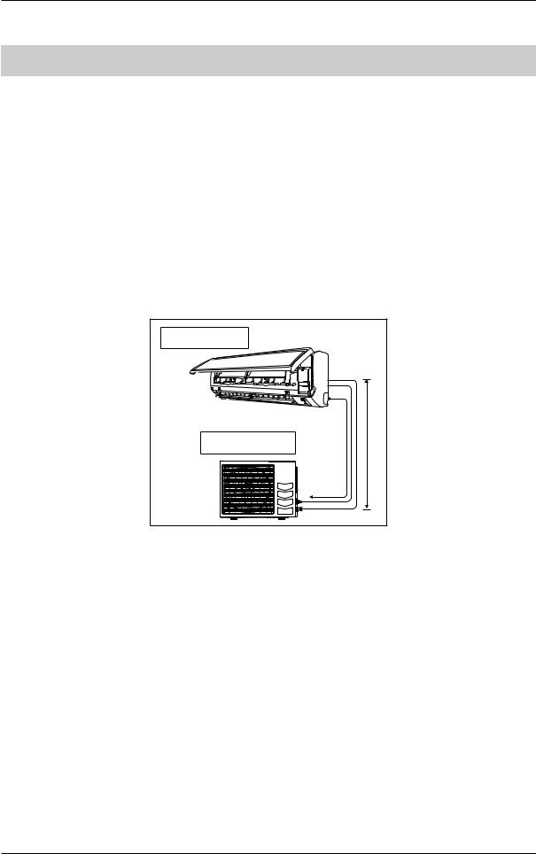
Inverter Single Split
1.3 Piping Length & Elevation
Model |
Max. total piping |
Max. height |
Pre-charge for up |
Additional |
|
length, L (m) |
difference, E (m) |
to piping length (m) |
charge (g/m) |
||
|
|||||
RXN25, ARXN25, |
20 |
10 |
7.5 |
20 |
|
RXK25 |
|||||
|
|
|
|
||
RXN35, ARXN35, |
20 |
10 |
7.5 |
20 |
|
RXK35 |
|||||
|
|
|
|
||
RXN50, ARXN50, |
30 |
10 |
7.5 |
20 |
|
RXB50, RXK50 |
|||||
|
|
|
|
||
RXN60, ARXN60, |
30 |
10 |
7.5 |
20 |
|
RXB60, RXK60 |
|||||
|
|
|
|
||
RXC25 |
20 |
15 |
7.5 |
17 |
|
|
|
|
|
|
|
RXC35 |
20 |
15 |
7.5 |
17 |
|
|
|
|
|
|
|
RXC50 |
30 |
15 |
7.5 |
17 |
|
|
|
|
|
|
|
RXC60 |
30 |
15 |
7.5 |
17 |
|
|
|
|
|
|
Indoor unit |
|
|
Outdoor Unit |
L |
E |
17
Downloaded from www.Manualslib.com manuals search engine
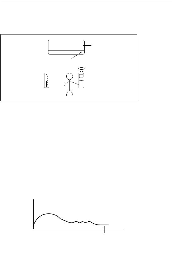
Algorithm & Control
2.0Function & Control
2.1Temperature Control
The temperature is detected by the room temperature thermistor (either on the unit or on the wired panel). The set temperature can be selected either through remote controller or wired controller by user.
Target temperature
Room thermistor temperature
Set temperature
Room temperature
2.2 Cooling and Heating Mode Operation
The system has 5 operating modes. The mode selection is done through the indoor by using the handset. The operating modes are:
•Cool
•Heat
•Fan
•Auto
•Dry
2.2.1 Cooling Mode
When Tr ≥ Ts+ 1.5°C
• Compressor, Indoor Fan and Outdoor Fan ON.
When Tr ≤ Ts- 2°C
• Compressor and Outdoor Fan OFF. Indoor Fan remained ON.
Tr = Room Temperature
Ts = Set Temperature
When cooling load is too small and the room temperature still drops below compressor cut off point, compressor will stop.
Compressor Capacity
Lowest Frequency
 Time
Time
T Ts - 2°C
Compresor will stop
18
Downloaded from www.Manualslib.com manuals search engine
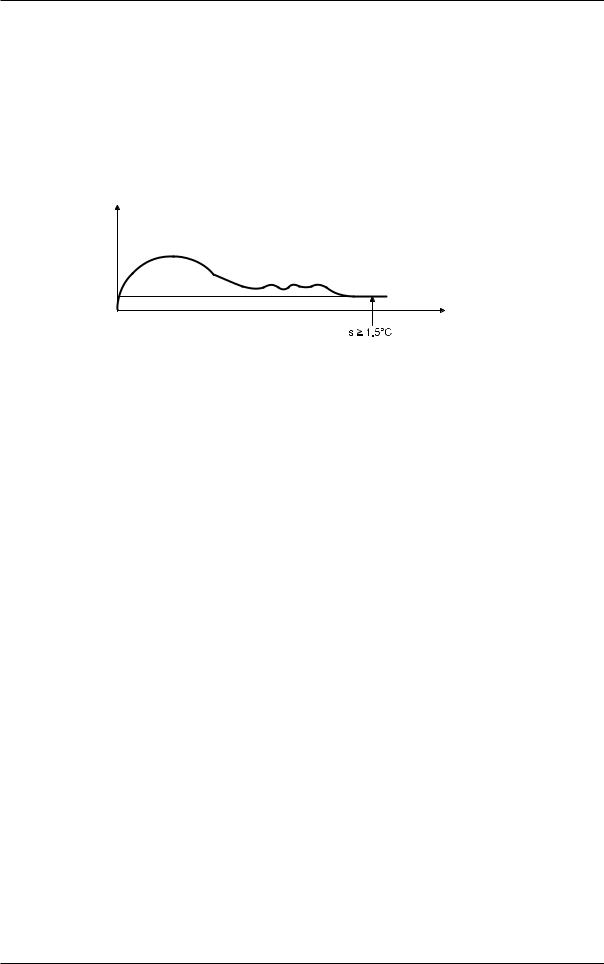
Algorithm & Control
2.2.2 Heating Mode:
When Ts> Tr - 1.0°C
• Compressor, Indoor Fan and Outdoor Fan ON.
When Ts ≤ Tr - 1.5°C
• Compressor and Outdoor Fan OFF. Indoor Fan speed will change to Super Low.
Tr = Room Temperature
Ts = Set Temperature
When heating load is too small, and the room temperature is still rising above compressor cut off point, compressor will stop.
Compressor Capacity
Lowest Frequency
Time |
Tr - T
Compressor will stop
2.3 Fan Mode
• Compressor and Outdoor Fan OFF. Indoor Fan remains ON.
• Only High, Medium and Low fan speeds are allowed.
• When changing cool mode to fan mode, the compressor will stop and outdoor fan stops based on fan OFF control.
• Compressor only ON if the minimum stop time is > 3 minutes and the user change back to cool mode.
• Fan speed will maintain same as during fan mode.
2.4 Auto Mode
Automatic Cooling / Heating Function
When the automatic operation is selected with the remote controller, the microcomputer automatically determines the operation mode as cooling or heating according to the room temperature and the set temperature at start-up.
The unit automatically switches the operation mode to maintain the room temperature at the set temperature. For heat pump only
Mode switching point:
•From Heating to Cooling
Tr ≥ Ts+ 2.5
•From Cooling to Heating
Tr ≤ Ts– 2.5
During initial operation
•Cooling operation: Tr > Ts
•Heating operation: Tr < Ts
19
Downloaded from www.Manualslib.com manuals search engine
 Loading...