


INSTALLATION
MANUAL
WALL MOUNTED
R410A SPLIT TYPE AIR CONDITIONER
Installation Manual |
English |
|
R410A Split Type Air Conditioner |
||
|
||
Руководство по установке |
|
|
|
||
|
||
R410A разделить Кондиционер |
Русский |
|
воздуха типа |
||
|
||
|
|
MODELS
ATYN20LV1 ARYN20LV1
ATYN25LV1 ARYN25LV1
ATYN35LV1 ARYN35LV1
ATYN50LV1 ARYN50LV1
ATYN60LV1 ARYN60LV1
IM-5WMJR-0515(0)-DAIKIN SIESTA
Part No.: R08019043338

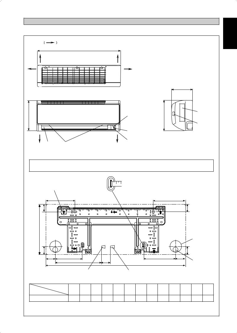
OUTLINE AND DIMENSIONS
Indoor Unit [ATYN]
THE MARK |
SHOWS PIPING DIRECTION |
|
A |
REAR |
REAR |
LEFT |
RIGHT |
 C TOP VIEW
B |
|
SIGNAL RECEIVER |
NAME PLATE |
|
|
||
|
B |
|
|
|
|
|
TERMINAL |
|
|
|
BLOCK |
|
|
INDOOR UNIT |
WITH EARTH |
|
|
TERMINAL |
|
|
|
ON/OFF SWITCH |
|
BOTTOM |
BOTTOM |
SIDE VIEW |
|
ROOM TEMPERATURE |
|
||
|
|
|
|
LOUVER |
FRONT GRILLE FIXED SCREWS |
THERMISTOR (INSIDE) |
|
|
|
(INSIDE)
FRONT VIEW
NOTE: PLEASE BASED ON ACTUAL INSTALLATION PLATE DESIGN IN THE UNIT FOR INSTALLATION PLATE 20/25/35J DIMENSION REFERENCE AT PAGE 1&2.
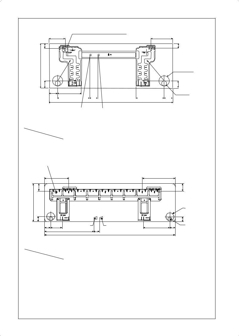
«Recommended mounting plate retention spots (5 spots in all)
D
F
B
Use tape measure as shown.
Position the end of a tape measure at Ñ
E
F
Through the wall hole Ø 65mm
G |
|
|
|
|
|
|
|
|
|
|
|
G |
|
|
|
|
|
|
|
|
|
|
|
|
|
|
|
||
H |
J |
|
L |
M |
|
|
|
|
K |
|
I |
|
|
|
|
|
|
A |
|
|
|
|
|
Drain hose position |
|||||
|
|
|
|
|
|
|
|
|
|
|||||
|
|
|
|
|
|
|
|
|
|
|
|
|
||
|
|
Liquid pipe end |
|
|
Gas pipe end |
|
|
|
|
|
|
|
||
|
|
|
INSTALLATION PLATE 20/25/35J |
|
|
|
|
|
|
|||||
Dimension |
A |
B |
C |
D |
E |
F |
G H |
I |
J |
K |
L M |
|||
Model |
||||||||||||||
|
|
|
|
|
|
|
|
|
|
|
|
|
||
20/25/35J |
800 |
288 |
206 |
166 |
184 |
42 |
46 |
55 |
56 |
154 |
182 |
263 |
52 |
|
All dimensions are in mm
Original Instruction English
1-1
F
B
G
«Recommended mounting plate retention spots (5 spots in all)
D E
H J
L |
|
|
M |
A |
K |
|
I |
Liquid pipe end |
|
|
|
|
|||
|
Gas pipe end |
|
|||||
ALTERNATIVE INSTALLATION PLATE 20/25/35J
F
Through the wall hole Ø 65mm
G
Drain hose position
|
Dimension |
A |
B |
C |
D |
E |
F |
G |
H |
I |
J |
K |
L |
M |
Model |
|
|||||||||||||
|
|
|
|
|
|
|
|
|
|
|
|
|
|
|
|
|
|
|
|
|
|
|
|
|
|
|
|
|
|
20/25/35J |
|
800 |
288 |
206 |
104 |
141 |
30 |
46 |
55 |
56 |
153 |
181 |
207 |
52 |
|
|
|
|
|
|
|
|
|
|
|
|
|
|
|
«Recommended mounting plate retention spots (7 spots in all)
D |
E |
F |
F |
B
|
|
|
|
|
|
Through the wall |
|
|
|
|
|
|
hole Ø 65mm |
G |
|
|
|
|
|
G |
H |
J |
Liquid pipe end |
Gas pipe end |
K |
I |
Drain hose position |
|
|
L |
M |
|
|
|
|
|
|
A |
|
|
|
|
|
|
INSTALLATION PLATE 50/60J |
|
|
|
Model |
Dimension |
A |
B |
C |
D |
E |
F |
G |
H |
I |
J |
K |
L |
M |
|
||||||||||||||
|
|
|
|
|
|
|
|
|
|
|
|
|
|
|
|
|
|
|
|
|
|
|
|
|
|
|
|
|
|
50/60J |
|
1065 |
310 |
224 |
190 |
173 |
61 |
40 |
45 |
48 |
91 |
219 |
580 |
45 |
|
|
|
|
|
|
|
|
|
|
|
|
|
|
|
All dimensions are in mm
1-2

Outdoor Unit [ARYN]
|
|
|
L |
|
K |
|
L |
|
|
|
|
All dimensions are in mm |
|||
|
|
|
|
|
|
|
|
|
N |
|
|
||||
|
|
|
|
|
|
|
|
|
|
|
|
|
|
|
|
|
|
|
|
|
|
|
|
M |
|
|
|
|
|
|
|
|
|
|
|
|
|
|
|
|
C |
|
|
|
|
|
|
|
|
|
|
|
A |
|
|
T |
N |
C |
|
|
|
|
|
|
|
|
|
|
|
|
|
|
|
|
|
|
|
||
|
|
O |
|
|
D |
|
|
|
|
G |
H |
|
|
|
|
|
|
P |
|
|
|
|
|
|
F |
|
|
|
|
|
|
|
|
|
|
|
|
|
|
|
E |
|
|
|
|
|
|
|
|
B |
|
|
|
|
|
|
|
|
|
|
|
|
|
|
|
|
|
|
|
|
|
R |
|
|
|
|
|
|
|
|
|
|
|
|
|
|
|
S |
|
|
|
|
|
|
|
|
|
Q |
|
|
|
|
|
|
|
I |
J |
|
|
|
|
|
|
|
|
|
|
|
|
|
|
|
|
|
|
|
|
Model |
Dimension |
A |
B |
C |
D |
E |
F |
G H |
I |
J |
K |
L M N |
|||
|
|||||||||||||||
|
|
|
|
|
|
|
|
|
|
|
|
|
|
|
|
20C |
|
600 |
475 |
245 |
418 |
177 |
35 |
93 |
81 |
83 |
55 |
398 |
101 |
97 |
17 |
25/35C |
|
700 |
521 |
250 |
485 |
175 |
36 |
95 |
93 |
86 |
68 |
441 |
130 |
111 |
15 |
Model |
Dimension |
O |
P |
Q |
R |
S |
T |
|
|
|
|
|
|
|
|
|
|
|
|
|
|
|
|
|
|||||||
|
|
|
|
|
|
|
|
|
|
|
|
|
|
|
|
20C |
|
22 |
3 |
19 |
65 |
80 |
30 |
|
|
|
|
|
|
|
|
25/35C |
|
18 |
3 |
19 |
65 |
80 |
30 |
|
|
|
|
|
|
|
|
Outdoor Unit [ARYN]
|
|
|
L |
K |
|
L |
|
|
|
All dimensions are in mm |
|||
|
|
|
|
|
|
|
N |
|
|
||||
|
|
|
|
|
|
|
|
|
|
|
|
|
|
|
|
|
|
|
|
|
M |
|
|
|
|
|
|
|
|
|
|
|
|
|
Q |
|
|
|
|
|
|
|
|
|
|
A |
|
|
N |
|
C |
H |
|
|
|
|
|
O |
|
D |
|
|
F |
G |
|
|
|
||
|
|
|
|
|
|
|
|
|
|
|
|
||
|
|
|
|
|
|
|
|
E |
|
|
|
|
|
|
B |
|
|
|
|
|
|
|
|
|
|
|
|
|
|
|
|
|
|
|
S |
|
|
|
|
|
|
|
|
|
|
|
|
|
R |
|
|
|
|
|
|
|
P |
|
|
|
|
|
|
|
I |
J |
|
|
|
Model |
Dimension |
A |
B |
C |
D |
E |
F |
G |
H |
I |
J |
K |
L |
|
|||||||||||||
|
|
|
|
|
|
|
|
|
|
|
|
|
|
50C |
|
855 |
628 |
328 |
520 |
179 |
46 |
93 |
149 |
101 |
113 |
603 |
126 |
60C |
|
855 |
730 |
328 |
520 |
179 |
46 |
93 |
149 |
101 |
113 |
603 |
126 |
Model |
Dimension |
M |
N |
O |
P |
Q |
R |
S |
|
|
|
|
|
|
|
|
|
|
|
||||||||
|
|
|
|
|
|
|
|
|
|
|
|
|
|
50C |
|
164 |
15 |
34 |
23 |
362 |
73 |
75 |
|
|
|
|
|
60C |
|
164 |
15 |
34 |
23 |
362 |
73 |
75 |
|
|
|
|
|
|
|
|
|
|
|
1-3 |
|
|
|
|
|
|
|
English
INSTALLATION MANUAL
This manual provides the procedures of installation to ensure a safe and good standard of operation for the air conditioner unit.
Special adjustment may be necessary to suit local requirement.
Before using your air conditioner, please read this instruction manual carefully and keep it for future reference. This appliance is intended to be used by expert or trained users in shops, in light industry and on farms, or for commercial use by lay persons.
This appliance is not intended for use by persons, including children, with reduced physical, sensory or mental capabilities, or lack of experience and knowledge, unless they have been given supervision or instruction concerning use of the appliance by a person responsible for their safety.
Children should be supervised to ensure that they do not play with the appliance.
SAFETY PRECAUTIONS
!WARNING
•Installation and maintenance should be performed by qualified persons who are familiar with local code and regulation, and experienced with this type of appliance.
•All field wiring must be installed in accordance with the national wiring regulation.
•Ensure that the rated voltage of the unit corresponds to that of the name plate before commencing wiring work according to the wiring diagram.
•The unit must be GROUNDED to prevent possible hazard due to insulation failure.
•All electrical wiring must not touch the water piping or any moving parts of the fan motors.
•Confirm that the unit has been switched OFF before installing or servicing the unit.
•Risk of electric shock, can cause injury or death. Disconnect all remain electric power supplies before servicing.
•DO NOT pull out the power cord when the power is ON. This may cause serious electrical shocks which may result in the fire hazards.
•Keep the indoor and outdoor units, power cable and transmission wiring, at least 1m from TVs and radios, to prevent distorted pictures and static. {Depending on the type and source of the electrical waves, static may be heard even when more than 1m away}.
! CAUTION
Please take note of the following important points when installing.
•Do not install the unit where leakage of flammable gas may occur.
If gas leaks and accumulates around the unit, it may cause fire ignition.
•Ensure that drainage piping is connected properly.
If the drainage piping is not connected properly, it may cause water leakage which will dampen the furniture.
• Do not overcharge the unit.
This unit is factory pre-charged. Overcharge will cause over-current or damage to the compressor.
•Ensure that the unit’s panel is closed after service or installation.
Unsecured panels will cause the unit to operate noisily.
•Sharp edges and coil surfaces are potential locations which may cause injury hazards. Avoid from being in contact with these places.
•Before turning off the powersupply set the remote controller’s ON/OFFswitch to the “OFF” position to prevent the nuisance tripping of the unit. If this is not done, the unit’s fans will start turning automatically when power resumes, posing a hazard to service personnel or the user.
•Do not install the units at or near doorway.
•Do not operate any heating apparatus too close to the air conditioner unit or use in room where mineral oil, oil vapour oroil steam exist, this may cause plastic part to melt ordeform as a result of excessive heat or chemical reaction.
•When the unit is used in kitchen, keep flour away from going into suction of the unit.
•This unit is not suitable for factory used where cutting oil mist or iron powder exist or voltage fluctuates greatly.
•Do not install the units at area like hot spring or oil refinery plant where sulphide gas exists.
•Ensure the color of wires of the outdoor unit and the terminal markings are same to the indoors respectively.
•IMPORTANT : DO NOT INSTALL OR USE THE AIR CONDITIONER UNIT IN A LAUNDRY ROOM.
•Don’t use joined and twisted wires for incoming power supply.
•Theequipmentisnotintendedforuseinapotentiallyexplosive atmosphere.
1-4
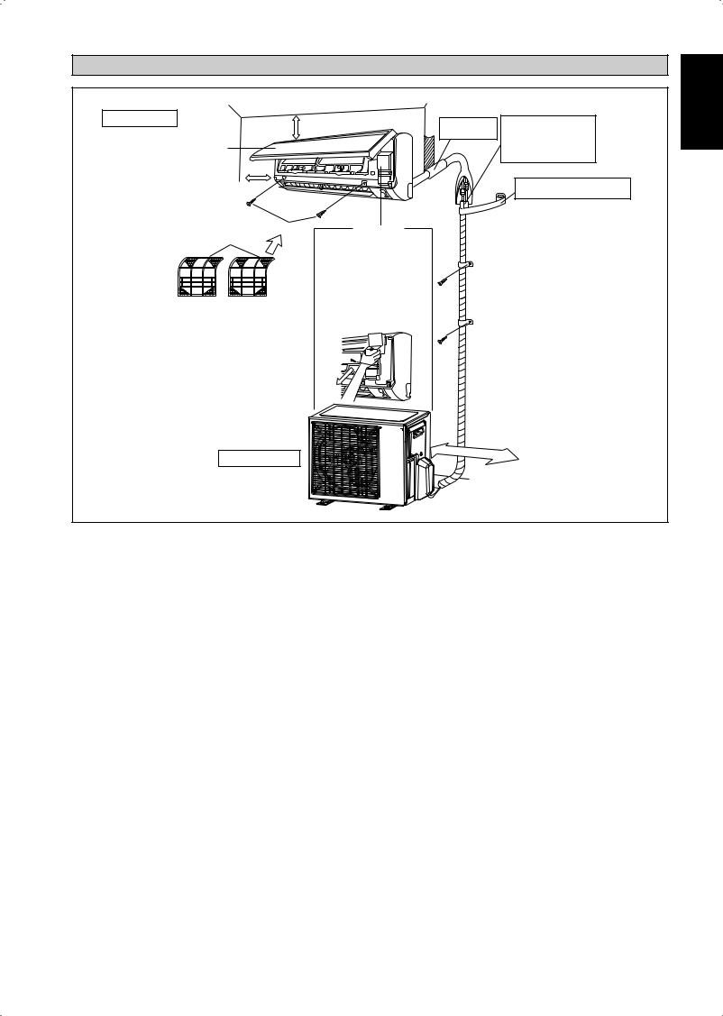
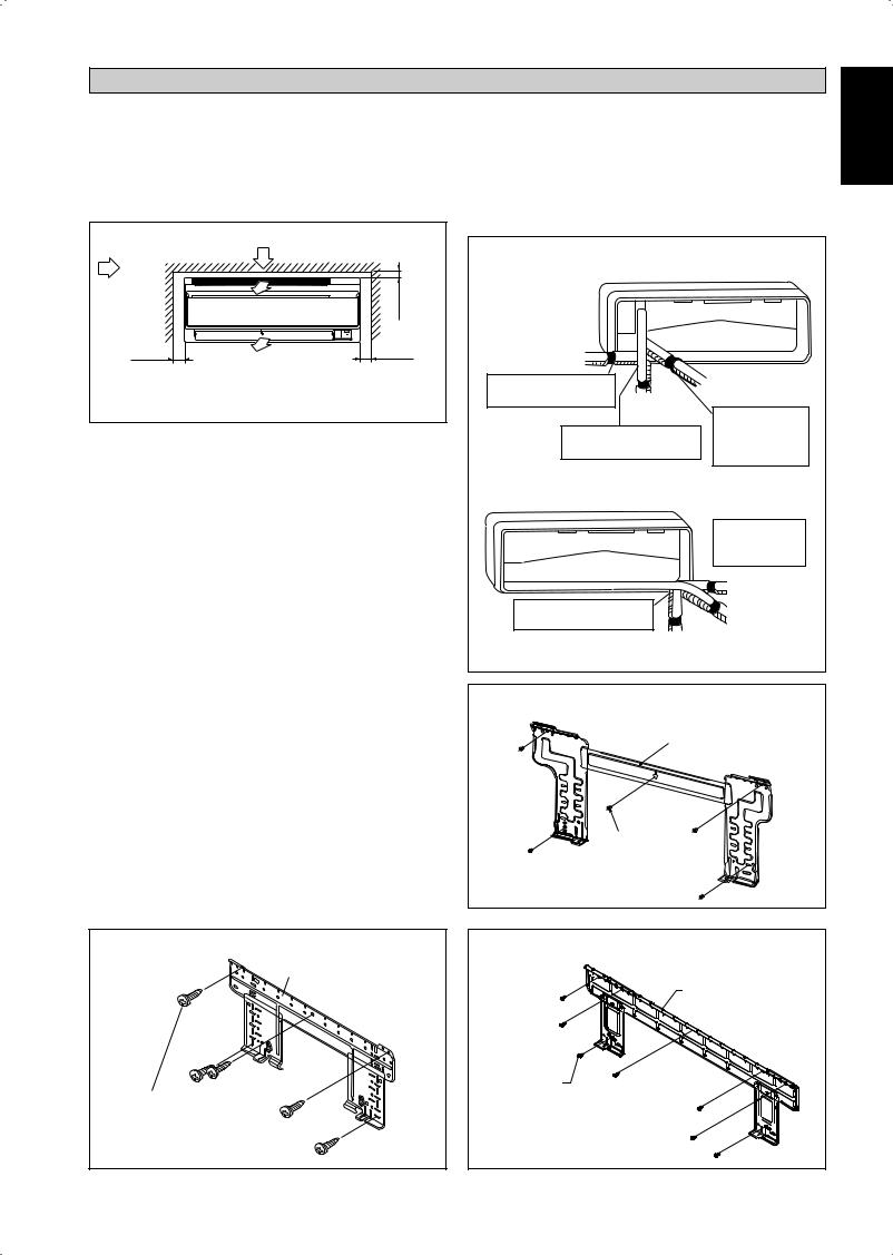
INSTALLATION DIAGRAM
Indoor unit |
|
75mm or more from ceiling |
Caulk pipe hole |
Cut thermal insulation pipe |
|
|
|
gap with putty. |
to an appropriate length and |
|
|
|
wrap it with tape, making |
|
|
|
|
|
|
Front panel |
|
|
|
sure that no gap is left in the |
|
|
|
|
insulation pipe’s cut line. |
50mm or more from walls |
|
|
|
Wrap the insulation pipe with the |
|
|
|
finishing tape from bottom to top. |
|
(on both sides) |
|
|
|
|
|
|
|
|
|
|
M4 x 12L |
Service lid |
|
|
Air filter |
|
|
|
|
|
¢ Opening service lid |
|
|
|
|
|
|
|
|
|
|
Service lid is opening/closing |
|
|
|
|
type. |
|
|
¢Opening method
1)Remove the service lid screws.
2)Pull out the service lid diagonally down in the direction of the arrow.
3)Pull down.
Outdoor Unit |
500mm |
from wall |
|
|
English
1-5
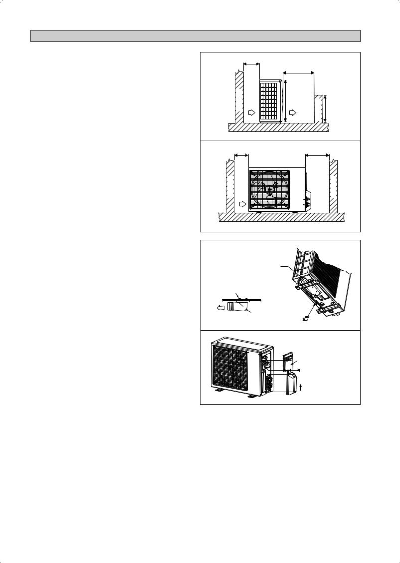
INSTALLATION OF THE OUTDOOR UNIT
The outdoor unit must be installed in such a way, so as to prevent short circuit of the hot discharged air or obstruction to the smooth air flow. Please follow the installation clearances shown in the figure. Select the coolest possible place where intake air temperature is not greater than the outside air temperature (please refer operating range).
Installation clearances
Dimension |
A |
B |
C |
D |
|
|
|
|
|
Minimum Distance, mm |
300 |
1000 |
300 |
500 |
|
|
|
|
|
Note: If there is any obstacle higher than half, of the unit’s height (H), please allow more space than the figure indicated in the above table.
Condensed Water Disposal Of Outdoor Unit
(Heat Pump Unit Only)
•There are 2 holes on the base of Outdoor Unit for condensed water to flow out. Insert the drain elbow to one of the holes.
•To install the drain elbow, first insert one portion of the hook to the base (portion A), then pull the drain elbow in the direction shown by the arrow while inserting the other portion to the base. After installation, check to ensure that the drain elbow clings to base firmly.
•If the unit is installed in a snowy and chilly area, condensed water may freeze in the base. In such case, please remove plug at the bottom of unit to smooth the drainage.
|
|
A |
|
|
|
|
|
|
|
|
B |
|
|
|
Obstacle |
Return air |
H |
Discharge air |
Obstacle |
H/2 |
|
|
|||||
|
C |
|
|
|
D |
|
Obstacle |
Return air |
|
|
|
Service access |
Obstacle |
PLUG |
A |
BASE |
DRAIN ELBOW |
DRAIN ELBOW |
Please remove side |
plate when connecting |
the piping and |
connecting cord |
PUSH & PULL UP |
1-6
INSTALLATION OF THE INDOOR UNIT
The indoor unit must be installed in such a way so as to prevent short circuit of the cool discharged air with the hot return air. Please follow the installation clearance shown in the figure. Do not place the indoor unit where there could be direct sunlight shining on it. Also, this location must be suitable for piping and drainage, and be away from doors or windows.
|
Return Air |
|
|
Air flow |
|
min. 75 (Space for performance) |
|
(Indoor) |
|
||
|
|
||
min. 50 |
Required space |
min. 50 |
|
(Space for |
(Space for |
||
|
|||
maintenance) |
|
maintenance) |
|
|
All dimensions are in mm |
||
Mounting Installation Plate
Ensure that the wall is strong enough to withstand the weight of the unit. Otherwise, it is necessary to reinforce the wall with plates, beams or pillars.
Use the level gauge for horizontal mounting, fix it with 5 suitable screws for 20/25/35J and 7 suitable screws for 50/60J.
In case the rear piping draws out, drill a hole 65mm in diameter with a cone drill, slightly lower on the outside wall (see figure).
20/25/35J
Mounting plate
The refrigerant piping can be routed to the unit in a number of ways (left or right from the back of the unit), by using the cut-out holes on the casing of the unit (see figure). Bend the pipes carefully to the required position in order to align it with the holes. For the side and bottom out, hold the bottom of the piping and then position it to the required direction (see figure). The condensation drain hose can be taped to the pipes.
Right-Side, Right-Back or Right-Bottom Piping
Right-side piping |
|
|
Remove pipe port cover |
Right-back piping |
|
|
||
here for right-side piping Right-bottom |
|
|
piping |
Bind coolant pipe |
|
Remove pipe port cover |
and drain hose |
|
together with |
||
here for right-bottom piping |
||
insulating tape. |
||
|
||
Left-Side, Left-Back or Left-Bottom Piping |
||
|
Remove pipe port |
|
|
cover here for |
|
|
left-side piping |
|
|
Left-side piping |
|
Remove pipe port cover |
Left-back piping |
|
here for left-bottom piping |
||
|
||
Left-bottom piping |
|
20/25/35J (ALTERNATIVE INSTALLATION PLATE)
Mounting plate
Mounting plate fixing screw
50/60J
Mounting plate
Mounting plate
Mounting plate fixing screw |
fixing screw |
English
1-7
Recommended Mounting Plate Retention Spots And
Dimensions
20/25/35J
« Recommended mounting plate |
Use tape measure as shown. |
|||
retention spots (5 spots in all) |
|
Position the end of a tape measure at Ñ |
||
|
166 |
|
|
184 |
42.2 |
|
|
|
42.2 |
288 |
|
|
|
Through the |
|
|
|
|
|
|
|
|
|
wall hole |
|
|
|
|
Ø 65mm |
45.9 |
|
|
|
45.9 |
54.5 |
153.8 |
|
181.7 |
55.5 |
|
263 |
51.9 |
800 |
Drain hose |
|
|
|
position |
|
|
Liquid pipe end |
|
Gas pipe end |
|
|
|
|
||
All dimensions are in mm
20/25/35J |
(ALTERNATIVE INSTALLATION PLATE) |
|
|
||
|
Recommended mounting plate retention spots |
|
|
||
|
(5 spots in all) |
|
|
|
|
104 |
|
|
141 |
|
|
30 |
|
|
|
30 |
|
|
|
|
|
Through the |
|
288 |
|
|
|
wall hole |
|
|
|
|
Ø 65mm |
||
|
|
|
|
||
46 |
|
|
|
46 |
Drain hose |
|
|
|
|
|
|
|
153 |
|
181 |
56 |
position |
55 |
207 |
52 |
|
||
|
|
800 |
|
|
|
|
Liquid pipe end |
Gas pipe end |
All dimensions are in mm |
||
|
|
|
|||
50/60J |
|
|
|
|
|
«Recommended mounting plate retention spots (7 spots in all)
|
190 |
|
|
173 |
|
|
61 |
|
|
|
|
|
61 |
310 |
|
|
|
|
|
Through the |
|
|
|
|
|
|
wall hole |
|
|
|
|
|
|
Ø 65mm |
40 |
|
|
|
|
|
40 |
45 |
91 |
Liquid pipe end |
Gas pipe end |
219 |
48 |
Drain hose |
|
|
580 |
45 |
|
|
position |
|
|
|
1065 |
|
|
All dimensions are in mm
Hole With Cone Drill
Inside |
Outside |
Wall embedded pipe |
Caulking |
(Field supply) |
|
Wall hole cover |
Ø 65 |
|
|
(Field supply) |
Wall embedded pipe |
|
|
|
(Field supply) |
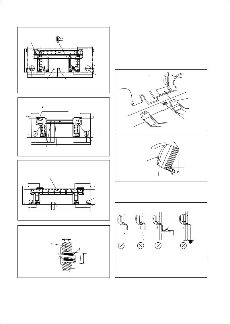
Mount The Unit Onto The Installation Plate
Hook the indoor unit onto the upper portion of the installation plate (Engage the two hooks at the rear top of the indoor unit with the upper edge of the installation plate). Ensure that the hooks are properly seated on the installation plate by moving it to the left and right.
How To Attach The Indoor Unit
Hook the claws of the bottom frame to the mounting plate.
How To Remove The Indoor Unit
Push up the marked area (at the lower part of the front grille) to release the claws.
Mounting plate
Clip
Bottom frame
Mark (rear side)
Front grille
Hang indoor unit’s hook here.
When stripping the |
Mounting plate |
|
|
ends of interconnecting |
|
wires in advance, bind |
|
right ends of wires with |
Interconnecting |
insulating tape. |
wires |
|
Wire guide |
Water Drainage Piping
The indoor drain pipe must be in a downward gradient for smooth drainage. Avoid situations that are likely to cause water to leak.
Water Drainage
|
|
Water |
|
|
|
Retention |
|
Water |
Water |
Water |
End dipped |
leaking |
leaking |
leaking |
into water |
 Drain
Drain
Correct |
Wrong |
Wrong |
Wrong |
!CAUTION
•Do not install the unit at altitude over 2000m for both
indoor and outdoor.
1-8
REFRIGERANT PIPING
If the pipe is too long, both the capacity and reliability of the unit will drop. As the number of bends increases, resistance to the flow of refrigerant system increases, thus lowering cooling capacity. As a result, the compressor may become defective. Always choose the shortest path and follow the recommendations as tabulated below:
Indoor unit |
|
|
Outdoor Unit |
L |
E |
|
|
Heat Pump Model
Model |
|
Indoor (ATYN) |
20J |
25J |
35J |
50J |
60J |
|
|
Outdoor (ARYN) |
20C |
25C |
35C |
50C |
60C |
Min. Allowable Length (L), m |
|
|
3 |
|
|
||
Max. Allowable Length (L), m |
12 |
12 |
12 |
20 |
20 |
||
Max. Allowable Elevation (E), m |
5 |
5 |
5 |
15 |
15 |
||
Gas Pipe Size, mm/(in) |
|
9.52 |
9.52 |
12.70 |
12.70 |
15.88 |
|
|
|
|
(3/8") |
(3/8") |
(1/2") |
(1/2") |
(5/8") |
Liquid Pipe Size, mm/(in) |
6.35 |
6.35 |
6.35 |
6.35 |
6.35 |
||
|
|
|
(1/4") |
(1/4") |
(1/4") |
(1/4") |
(1/4") |
*Be sure to add the proper amount of additional refrigerant. Failure to do so may result in reduced performance.
Remark: The refrigerant pre-charged in the outdoor unit is for piping length up to 7.5m.
English
1-9
Equivalent length for various fitting (meter)
Pipe Size |
L joint |
Trap bend |
||
|
|
|
|
|
|
|
|
|
|
|
|
|
|
|
3/8" (OD9.52mm) |
0.18 |
|
1.3 |
|
1/2" (OD12.7mm) |
0.20 |
|
1.5 |
|
5/8" (OD15.9mm) |
0.25 |
|
2 |
|
3/4" (OD19.1mm) |
0.35 |
|
2.4 |
|
7/8" (OD22.2mm) |
0.40 |
|
3 |
|
1" (OD25.4mm) |
0.45 |
|
3.4 |
|
1 1/8" (OD28.6mm) |
0.50 |
|
3.7 |
|
1 3/8" (OD34.9mm) |
0.60 |
|
4.4 |
|
Notes:
1.Equivalent piping length is obtained with actual length of gas piping.
2.90° bend of piping is equivalent to L joint.
Bending must be carefully made so as not to crush the pipe. Use a pipe bender to bend a pipe where possible.
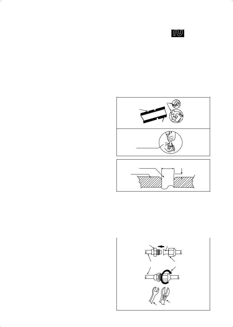
Piping Works And Flaring Technique
•Do not use contaminated or damaged copper tubing. If any piping, evaporator or condenser had been exposed or had been opened for 15 seconds or more, the system must be vacuumed. Generally do not remove plastic, rubber plugs and brass nuts from the valves, fittings, tubing and coils until it is ready to connect suction or liquid line into valves or fittings.
•If any brazing work is required, ensure that nitrogen gas is passed through coil and joints while the brazing work is being done. This will eliminate soot formation on the inside wall of copper tubings.
•Cut the pipe stages by stages, advancing the blade of pipe cutter slowly. Extra force and a deep cut will cause more distortion of pipe and therefore extra burr. See Figure I.
•Remove burrs from cut edges of the pipes with remover. See Figure II. Hold the pipe on top position and burr remover at lower position to prevent metal chips from entering the pipe. This will avoid unevenness on the flare faces which will cause gas leak.
•Insert the flare nuts, mounted on the connection parts of both the indoor unit and outdoor unit, into the copper pipes.
•The exact length of pipe protruding from the top surface of the swaging block is determined by the flaring tool. See Figure III.
•Fix the pipe firmly on the swaging block. Match the centers of both the swaging block and the flaring punch, then tighten the flaring punch fully.
Piping Connection To The Units
•Align the center of the piping and tighten the flare nut sufficiently with fingers. See Figure IV.
•Finally, tighten the flare nut with torque wrench until the wrench clicks.
•When tightening the flare nut with the torque wrench, ensure that the tightening direction follows the arrow indicated on the wrench.
•The refrigerant pipe connection are insulated by closed cell polyurethane.
Pipe Size (mm/in) |
Torque, Nm/(ft-lb) |
|
|
6.35 (1/4") |
18 (13.3) |
|
|
9.52 (3/8") |
42 (31.0) |
|
|
12.70 (1/2") |
55 (40.6) |
|
|
15.88 (5/8") |
65 (48.0) |
|
|
19.05 (3/4") |
78 (57.6) |
|
|
Figure I |
Cutting Copper Tube |
|
|
|
1/4t |
Copper Tube
Figure II
Remove Burr
Figure III
Copper Tube |
D |
Swaging Block |
A |
|
Ø Tube, D |
|
A (mm) |
||||
Inch |
|
mm |
|
Imperial |
|
Rigid |
|
|
|
(Wing-nut Type) |
|
(Clutch Type) |
|
1/4" |
|
6.35 |
|
1.3 |
|
0.7 |
3/8" |
|
9.52 |
|
1.6 |
|
1.0 |
1/2" |
|
12.70 |
|
1.9 |
|
1.3 |
5/8" |
|
15.88 |
|
2.2 |
|
1.7 |
3/4" |
|
19.05 |
|
2.5 |
|
2.0 |
|
|
|
|
|
|
|
Figure IV |
Flare Joint |
Flared Tube |
|
|||
Indoor Piping |
Flare Nut |
Torque Wrench
Spanner
1-10
 Loading...