


OBJ_BUCH-1559-002.book Page 1 Monday, October 17, 2016 7:27 PM
Robert Bosch Power Tools GmbH
70538 Stuttgart
GERMANY
GOF | GMF 1600 CE Professional
www.bosch-pt.com
2 610 041 862 (2016.10) T / 66
en Original instructions cn tw
ko
th
id Petunjuk-Petunjuk untuk Penggunaan Orisinal vi Bản gốc hướng dẫn sử dụng

OBJ_BUCH-1559-002.book Page 2 Monday, October 17, 2016 7:29 PM
2 |
English . . . . . . . . . . . . . . . . . . . . . . . . . . . . . . . . . . . . . . . . . . Page 10
. . . . . . . . . . . . . . . . . . . . . . . . . . . . . . . . . . . . . . . . . . . . . . 18
. . . . . . . . . . . . . . . . . . . . . . . . . . . . . . . . . . . . . . . . . . . . . . 25
. . . . . . . . . . . . . . . . . . . . . . . . . . . . . . . . . . . . . . . . 31. . . . . . . . . . . . . . . . . . . . . . . . . . . . . . . . . . . . . . . . . 39 Bahasa Indonesia . . . . . . . . . . . . . . . . . . . . . . . . . . . . . . Halaman 46 Tiếng Việt . . . . . . . . . . . . . . . . . . . . . . . . . . . . . . . . . . . . . . . . . . . . . . Trang 55
2 610 041 862 | (17.10.16) |
|
|
Bosch Power Tools |
||||
|
|
|
|
|
|
|
|
|
|
|
|
|
|
|
|
|
|
|
|
|
|
|
|

OBJ_BUCH-1559-002.book Page 3 Monday, October 17, 2016 7:29 PM |
|
|
| 3 |
1 |
|
2 |
|
|
3 |
GOF 1600 CE |
|
Professional |
4 |
4 |
|
Bosch Power Tools |
2 610 041 862 | (17.10.16) |
OBJ_BUCH-1559-002.book Page 4 Monday, October 17, 2016 7:29 PM |
|
|
4 | |
|
|
5 |
15 |
|
6 |
||
|
||
7 |
|
|
8 |
|
|
9 |
|
|
10 |
|
|
11 |
|
|
|
16 |
|
|
17 |
|
|
18 |
|
12 |
|
|
13 |
|
|
14 |
|
|
19 |
|
|
20 |
|
|
|
21 |
|
|
22 |
|
|
23 |
|
GOF 1600 CE |
|
|
Professional |
|
|
2 610 041 862 | (17.10.16) |
Bosch Power Tools |
OBJ_BUCH-1559-002.book Page 5 Monday, October 17, 2016 7:29 PM |
|
|
| 5 |
19 |
24 |
20 |
|
|
21 |
|
22 |
|
25 |
|
23 |
GMF 1600 CE |
|
Professional |
|
Bosch Power Tools |
2 610 041 862 | (17.10.16) |
OBJ_BUCH-1559-002.book Page 6 Monday, October 17, 2016 7:29 PM
6 |
A  B
B
1
26
C |
D |
18  17
17

 27
27
1 |
|
|
|
|
21 |
|
|
|
|
22 |
|
|
|
|
|
|
|
28 |
|
E |
|
|
F |
29 |
|
|
|
|
|
29 |
|
|
|
33 |
|
|
|
|
|
|
30 |
31 |
32 |
31 |
|
|
|
||
2 610 041 |
862 | (17.10.16) |
|
|
Bosch Power Tools |
OBJ_BUCH-1559-002.book Page 7 Monday, October 17, 2016 7:29 PM
9 |
10 |
11 |
16 |
12 |
I |
18 |
| 7 |
24 |
34 |
21 |
25 |
22 |
J |
K |
35 |
|
38 |
||
|
||
37 |
39 |
|
36 |
|
|
|
40 |
|
|
41 |
|
Bosch Power Tools |
2 610 041 862 | (17.10.16) |

OBJ_BUCH-1559-002.book Page 8 Monday, October 17, 2016 7:29 PM |
|
|||
8 | |
|
|
|
|
L |
42 |
|
42 |
|
45 |
46 |
|||
43 44 |
|
|||
|
|
47 |
|
|
|
|
48 |
49 |
|
N |
|
O |
|
|
50 |
51 |
51 |
50 |
P |
|
Q |
|
|
|
|
53 |
|
|
|
14 |
|
50 |
52 |
|
|
|
53 |
|
2 610 041 862 | (17.10.16) |
|
|
Bosch Power Tools |
OBJ_BUCH-1559-002.book Page 9 Monday, October 17, 2016 7:29 PM |
|
||||
|
|
|
|
|
| 9 |
R |
54 55 |
14 |
|
54 55 |
14 |
|
|
|
|
|
|
2 |
|
|
|
3 |
|
|
|
|
|
|
|
S |
56 |
|
57 |
T |
|
|
|
59 |
3 |
U |
60 |
|
|
|
|
24 |
|
|
|
59 |
|
58 |
|
Bosch Power Tools |
|
2 610 041 862 | (17.10.16) |

OBJ_BUCH-1559-002.book Page 10 Monday, October 17, 2016 7:29 PM
10 | English
English
Safety Notes
General Power Tool Safety Warnings
WARNING Read all safety warnings and all instructions. Failure to follow the warnings and
instructions may result in electric shock, fire and/or serious injury.
Save all warnings and instructions for future reference.
The term “power tool” in the warnings refers to your mainsoperated (corded) power tool or battery-operated (cordless) power tool.
Work area safety
Keep work area clean and well lit. Cluttered or dark areas invite accidents.
Do not operate power tools in explosive atmospheres, such as in the presence of flammable liquids, gases or dust. Power tools create sparks which may ignite the dust or fumes.
Keep children and bystanders away while operating a power tool. Distractions can cause you to lose control.
Electrical safety
Power tool plugs must match the outlet. Never modify the plug in any way. Do not use any adapter plugs with earthed (grounded) power tools. Unmodified plugs and matching outlets will reduce risk of electric shock.
Avoid body contact with earthed or grounded surfaces, such as pipes, radiators, ranges and refrigerators.
There is an increased risk of electric shock if your body is earthed or grounded.
Do not expose power tools to rain or wet conditions.
Water entering a power tool will increase the risk of electric shock.
Do not abuse the cord. Never use the cord for carrying, pulling or unplugging the power tool. Keep cord away from heat, oil, sharp edges and moving parts. Damaged or entangled cords increase the risk of electric shock.
When operating a power tool outdoors, use an extension cord suitable for outdoor use. Use of a cord suitable for outdoor use reduces the risk of electric shock.
If operating a power tool in a damp location is unavoidable, use a residual current device (RCD) protected supply. Use of an RCD reduces the risk of electric shock.
Personal safety
Stay alert, watch what you are doing and use common sense when operating a power tool. Do not use a power tool while you are tired or under the influence of drugs, alcohol or medication. A moment of inattention while operating power tools may result in serious personal injury.
Use personal protective equipment. Always wear eye protection. Protective equipment such as dust mask, non-skid safety shoes, hard hat, or hearing protection used for appropriate conditions will reduce personal injuries.
Prevent unintentional starting. Ensure the switch is in the off-position before connecting to power source and/or battery pack, picking up or carrying the tool.
Carrying power tools with your finger on the switch or energising power tools that have the switch on invites accidents.
Remove any adjusting key or wrench before turning the power tool on. A wrench or a key left attached to a rotating part of the power tool may result in personal injury.
Do not overreach. Keep proper footing and balance at all times. This enables better control of the power tool in unexpected situations.
Dress properly. Do not wear loose clothing or jewellery. Keep your hair, clothing and gloves away from moving parts. Loose clothes, jewellery or long hair can be caught in moving parts.
If devices are provided for the connection of dust extraction and collection facilities, ensure these are connected and properly used. Use of dust collection can reduce dust-related hazards.
Power tool use and care
Do not force the power tool. Use the correct power tool for your application. The correct power tool will do the job better and safer at the rate for which it was designed.
Do not use the power tool if the switch does not turn it on and off. Any power tool that cannot be controlled with the switch is dangerous and must be repaired.
Disconnect the plug from the power source and/or the battery pack from the power tool before making any adjustments, changing accessories, or storing power tools. Such preventive safety measures reduce the risk of starting the power tool accidentally.
Store idle power tools out of the reach of children and do not allow persons unfamiliar with the power tool or these instructions to operate the power tool. Power tools are dangerous in the hands of untrained users.
Maintain power tools. Check for misalignment or binding of moving parts, breakage of parts and any other condition that may affect the power tool’s operation. If damaged, have the power tool repaired before use.
Many accidents are caused by poorly maintained power tools.
Keep cutting tools sharp and clean. Properly maintained cutting tools with sharp cutting edges are less likely to bind and are easier to control.
Use the power tool, accessories and tool bits etc. in accordance with these instructions, taking into account the working conditions and the work to be performed.
Use of the power tool for operations different from those intended could result in a hazardous situation.
Service
Have your power tool serviced by a qualified repair person using only identical replacement parts. This will ensure that the safety of the power tool is maintained.
2 610 041 862 | (17.10.16) |
|
|
Bosch Power Tools |
||||
|
|
|
|
|
|
|
|
|
|
|
|
|
|
|
|
|
|
|
|
|
|
|
|
OBJ_BUCH-1559-002.book Page 11 Monday, October 17, 2016 7:29 PM
Safety Warnings for Routers
Hold power tool by insulated gripping surfaces, because the cutter may contact its own cord. Cutting a “live” wire may make exposed metal parts of the power tool “live” and shock the operator.
Use clamps or another practical way to secure and support the workpiece to a stable platform. Holding the work by your hand or against the body leaves it unstable and may lead to loss of control.
The allowable speed of the router bit must be at least as high as the maximum speed listed on the power tool.
Accessories that rotate faster than permitted can be destroyed.
Router bits or other accessories must fit exactly in the tool holder (collet) of your machine. Routing bits that do not fit precisely in the tool holder of the machine rotate irregularly, vibrate heavily and can lead to loss of control.
Apply the machine to the workpiece only when switched on. Otherwise there is danger of kickback when the cutting tool jams in the workpiece.
Keep your hands away from the routing area and the router bit. Hold the auxiliary handle or the motor housing with your second hand. When both hands hold the machine, they cannot be injured by the router bit.
Never cut over metal objects, nails or screws. The router bit can become damaged and lead to increased vibrations.
Use suitable detectors to determine if utility lines are hidden in the work area or call the local utility company for assistance. Contact with electric lines can lead to fire and electric shock. Damaging a gas line can lead to explosion. Penetrating a water line causes property damage or may cause an electric shock.
Do not use blunt or damaged router bits. Blunt or damaged router bits cause increased friction, can become jammed and lead to imbalance.
When working with the machine, always hold it firmly with both hands and provide for a secure stance. The power tool is guided more secure with both hands.
Always wait until the machine has come to a complete stop before placing it down. The tool insert can jam and lead to loss of control over the power tool.
Products sold in GB only: Your product is fitted with a BS 1363/A approved electric plug with internal fuse (ASTA approved to BS 1362).
If the plug is not suitable for your socket outlets, it should be cut off and an appropriate plug fitted in its place by an authorised customer service agent. The replacement plug should have the same fuse rating as the original plug.
The severed plug must be disposed of to avoid a possible shock hazard and should never be inserted into a mains socket elsewhere.
Products sold in AUS and NZ only: Use a residual current device (RCD) with a rated residual current of 30 mA or less.
English | 11
Product Description and Specifications
Read all safety warnings and all instructions. Failure to follow the warnings and instructions may result in electric shock, fire and/or serious injury.
Intended Use
The machine is intended for routing grooves, edges, profiles and elongated holes as well as for copy routing in wood, plastic and light building materials, while resting firmly on the workpiece.
With reduced speed and with appropriate routing bits, nonferrous alloys can also be machined.
Product Features
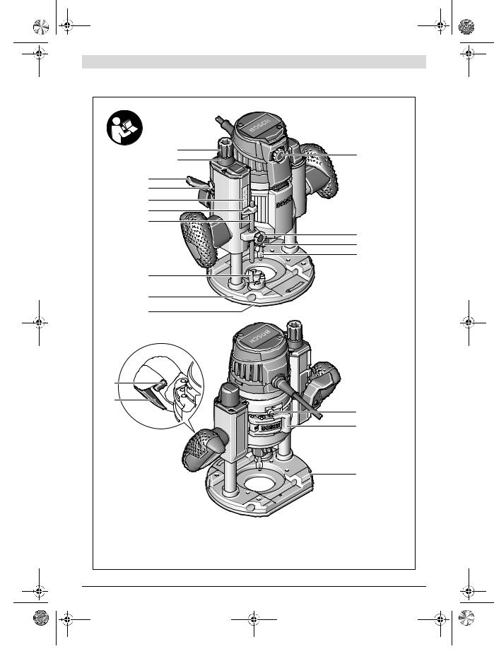
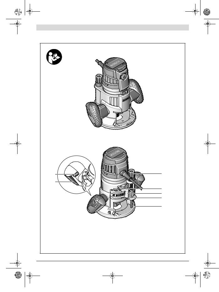
The numbering of the product features refers to the illustration of the machine on the graphics page.
1 Routing motor
2 Plunge base
3 Non-plunge base
4 Handle (insulated gripping surface)
5Adjustment knob for fine adjustment of depth-of-cut (plunge base)
6 Scale for depth-of-cut fine adjustment 7 Release lever for plunge action
8 Index mark for fine adjustment
9 Scale for depth-of-cut adjustment (plunge base)
10Slide with index mark (plunge base)
11Depth stop (plunge base)
12Turret stop
13Base plate
14Guide plate
15Thumbwheel for speed preselection
16Knurled screw for depth stop (plunge base)
17Tightening nut with collet
18Router bit *
19Lock-on button for On/Off switch
20On/Off switch
21Securing latch for removal of motor
22Clamping lever for plunge base/non-plunge base
23Seat for parallel guide rods
24Adjustment knob for depth-of-cut fine adjustment (non-plunge base)
25Clamping lever for depth-of-cut coarse adjustment (non-plunge base)
26Coarse adjustment notches for non-plunge base
27Spindle lock button
28Open-end spanner, size 24 mm
29Knurled screw for extraction adapter (2x) *
30Extraction adapter (plunge base) *
31Extraction hose (Ø 35 mm) *
|
Bosch Power Tools |
2 610 041 862 | (17.10.16) |
|
||||
|
|
|
|
|
|
|
|
|
|
|
|
|
|
|
|
|
|
|
|
|
|
|
|

OBJ_BUCH-1559-002.book Page 12 Monday, October 17, 2016 7:29 PM
12 | English
32 |
Extraction adapter (non-plunge base) * |
47 |
Centring screw for compass stop * |
|
33 |
Intermediate ring for extraction adapter (non-plunge |
48 |
Base spacer |
|
|
base) * |
|
(included in the “router compass” set) * |
|
34 |
Scale for depth-of-cut adjustment |
49 |
Guide rail * |
|
|
(non-plunge base) |
50 |
SDS guide-bushing adapter |
|
35 |
Parallel guide * |
51 |
Fastening screw for guide bushing adapter (2x) |
|
36 |
Guide rod for parallel guide (2x) * |
52 |
Release lever for guide bushing adapter |
|
37 |
Wing bolt for fine adjustment of parallel guide (2x) * |
53 |
Guide bushing |
|
38 |
Wing bolt for coarse adjustment of |
54 |
Fastening screw for guide plate |
|
|
parallel guide (2x) * |
55 |
Centring pin |
|
39 |
Fine-adjustment knob for parallel guide* |
|||
56 |
Fastening screws for non-plunge base * |
|||
40 |
Adjustable edge guide for parallel guide * |
|||
57 |
Specialty Allen key for depth-of-cut fine adjustment |
|||
41 |
Wing bolt for guide rods of parallel guide (2x) * |
|||
|
(non-plunge base) * |
|||
42 |
Router compass/guide-rail adapter * |
58 |
Extension for depth-of-cut fine adjustment |
|
43 |
Router compass handle * |
|
(non-plunge base) * |
|
44 |
Wing bolt for coarse adjustment of |
59 |
Extraction hood for edge routing * |
|
|
router compass (2x) * |
60 |
Fastening screw for extraction hood * |
|
45 |
Wing bolt for fine adjustment of |
*Accessories shown or described are not part of the standard de- |
||
|
router compass (1x) * |
livery scope of the product. A complete overview of accessories |
||
46 |
Fine-adjustment knob for router compass * |
can be found in our accessories program. |
||
Technical Data
Multifunction Router |
|
GOF 1600 CE |
GMF 1600 CE |
Article number |
|
3 601 F24 0.. |
3 601 F24 0.. |
Rated power input |
W |
1 600 |
1 600 |
No-load speed |
min-1 |
10 000 – 25 000 |
10 000 – 25 000 |
Speed preselection |
|
|
|
Constant electronic control |
|
|
|
Connection for dust extraction |
|
|
|
Tool holder |
mm |
8 – 12 |
8 – 12 |
|
inch |
¼ – ½ |
¼ – ½ |
Plunge depth (plunge base) |
mm |
76 |
76 |
Weight according to EPTA-Procedure 01:2014 |
kg |
– |
4.3 |
– Contour router |
|||
– Plunge router |
kg |
5.8 |
5.8 |
Protection class |
|
/ II |
/ II |
The values given are valid for a nominal voltage [U] of 230 V. For different voltages and models for specific countries, these values can vary.
Assembly
Before any work on the machine itself, pull the mains plug.
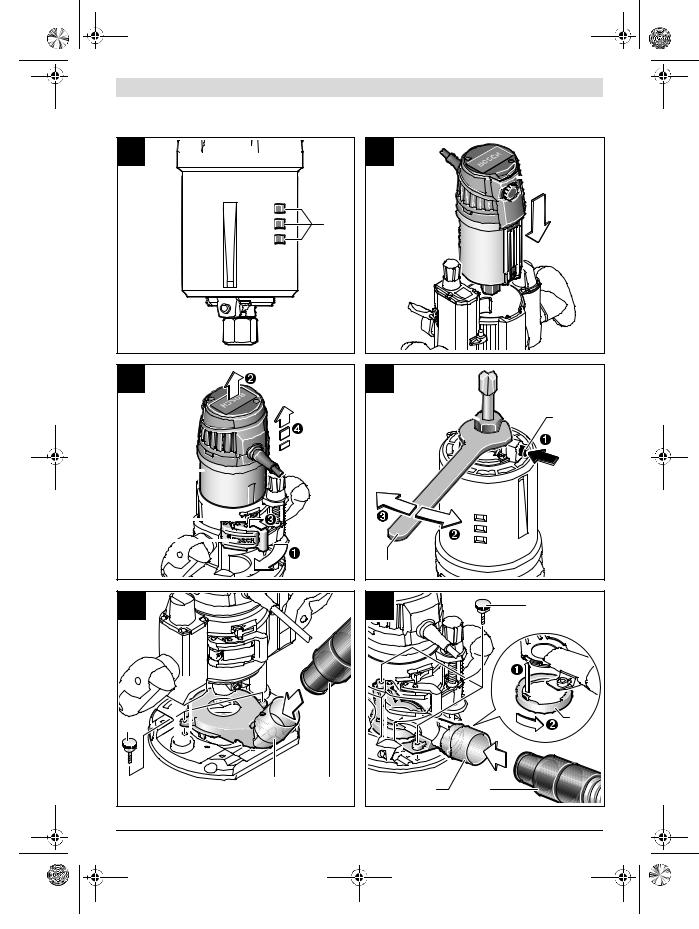
Inserting the Routing Motor into the Plunge Base/Non-plunge Base (see figures A –B)
–Open the clamping lever for the plunge base/non-plunge base 22.
–Push the routing motor to the stop into the plunge base/non-plunge base.
–When using the non-plunge base 3, press clamping lever 25 and slide the routing motor 1 up or down to the desired position in the non-plunge base 3, until it, with the clamping lever 25 released, engages in one of the 3 notches 26.
–Shut the clamping lever for the plunge unit/non-plunge base 22.
–Adjust the required depth-of-cut; see Section “Adjusting the Depth-of-cut”.
Separating the Routing Motor from the Plunge Unit/Nonplunge Base (see figure C)
–Open the clamping lever for the plunge base/non-plunge base 22.
–Pull the routing motor to the stop and and hold it in this position.
–Press securing latch 21 and pull the routing motor completely out of the plunge base/non-plunge base. When using the non-plunge base 3, additionally press clamping lever 25.
2 610 041 862 | (17.10.16) |
|
|
Bosch Power Tools |
||||
|
|
|
|
|
|
|
|
|
|
|
|
|
|
|
|
|
|
|
|
|
|
|
|

OBJ_BUCH-1559-002.book Page 13 Monday, October 17, 2016 7:29 PM
Inserting a Router Bit (see figure D)
It is recommended to wear protective gloves when inserting or replacing router bits.
Depending on the application, router bits are available in the most different designs and qualities.
Router bits made of high speed steel (HSS) are suitable for the machining of soft materials, e. g. softwood and plastic.
Carbide tipped router bits (HM) are particularly suitable for hard and abrasive materials, e. g. hardwood and aluminium.
Original router bits from the extensive Bosch accessories program are available at your specialist shop.
Use router bits with a shank diameter of 12 mm as far as this is possible. Only use clean router bits that are in perfect condition.
The router bit can be changed when the routing motor is mounted in the plunge base/non-plunge base. However, it is recommended to change the tool with the routing motor dismounted.
–Remove the routing motor from the plunge base/nonplunge base.
–Press and hold the spindle lock button 27 (). If required, turn the spindle by hand until the lock engages.
Actuate the spindle lock button 27 only when at a standstill.
–Loosen the tightening nut 17 with the open-end spanner 28 (size 24 mm) by turning in antclockwise direction ().
–Insert the router bit into the collet. The shank of the router bit must be immersed at least 20 mm into the collet.
–Tighten the tightening nut 17 with the open-end spanner 28 (size 24 mm) by turning in clockwise direction. Release the spindle lock button 27.
Do not insert a router bit with a diameter larger than 50 mm when the guide bushing is not mounted. Such router bits do not fit through the base plate.
Do not tighten the tightening nut of the collet without a router bit inserted. Otherwise the collet can be damaged.
Dust/Chip Extraction
Dust from materials such as lead-containing coatings, some wood types, minerals and metal can be harmful to one’s health. Touching or breathing-in the dust can cause allergic reactions and/or lead to respiratory infections of the user or bystanders.
Certain dust, such as oak or beech dust, is considered carcinogenic, especially in connection with wood-treatment additives (chromate, wood preservative). Materials containing asbestos may only be worked by specialists.
–As far as possible, use a dust extraction system suitable for the material.
–Provide for good ventilation of the working place.
–It is recommended to wear a P2 filter-class respirator.
Observe the relevant regulations in your country for the materials to be worked.
Prevent dust accumulation at the workplace. Dust can easily ignite.
English | 13
Mounting the Extraction Adapter to the Plunge Base (see figure E)
The extraction adapter 30 can be mounted with the hose connection facing toward the front or rear. When the guide-bush- ing adapter 50 is inserted, it may be required to mount the guide-bushing adapter turned by 180 °, so that the extraction adapter 30 does not touch the release lever 52. Fasten the extraction adapter 30 with the 2 knurled screws 29 to the base plate 13.
To ensure optimum extraction, the extraction adapter 30 must be cleaned regularly.
Mounting the Extraction Adapter to the Non-plunge Base (see figure F)
The extraction adapter 32 can be mounted with the hose connection facing toward the front or rear. When the guide-bush- ing adapter 50 is inserted, fasten the extraction adapter 32 with the 2 knurled screws 29 to the base plate 13. For applications without the guide-bushing adapter 50, firstly mount the intermediate ring 33 to the extraction adapter 32, as shown in the figure.
Connecting the Dust Extraction
Insert an extraction hose (Ø 35 mm) 31 (accessory) into the mounted extraction adapter. Connect the extraction hose 31 to a vacuum cleaner (accessory).
The machine can be plugged directly into the receptacle of a Bosch all-purpose vacuum cleaner with remote starting control. The vacuum cleaner starts automatically when the machine is switched on.
The vacuum cleaner must be suitable for the material being worked.
When vacuuming dry dust that is especially detrimental to health or carcinogenic, use a special vacuum cleaner.
Operation
Starting Operation
Observe correct mains voltage! The voltage of the power source must agree with the voltage specified on the nameplate of the machine. Power tools marked with 230 V can also be operated with 220 V.
Preselecting the Speed
The required speed can be preselected with the thumbwheel 15 (also while running).
1 – 2 low speed
3 – 4 medium speed
5 – 6 high speed
|
Bosch Power Tools |
2 610 041 862 | (17.10.16) |
|
||||
|
|
|
|
|
|
|
|
|
|
|
|
|
|
|
|
|
|
|
|
|
|
|
|

OBJ_BUCH-1559-002.book Page 14 Monday, October 17, 2016 7:29 PM
14 | English
The values shown in the chart are standard values. The necessary speed depends on the material and the operating conditions, and can be determined by practical testing.
Material |
Router bit diameter |
Thumb- |
|
|
(mm) |
wheel 15 |
|
Hardwood (Beech) |
4 – 10 |
5 – 6 |
|
|
12 |
– 20 |
3 – 4 |
|
22 |
– 40 |
1 – 2 |
Softwood (Pine) |
4 – 10 |
5 – 6 |
|
|
12 |
– 20 |
3 – 6 |
|
22 |
– 40 |
1 – 3 |
Particle Board |
4 – 10 |
3 – 6 |
|
|
12 |
– 20 |
2 – 4 |
|
22 |
– 40 |
1 – 3 |
Plastics |
4 – 15 |
2 – 3 |
|
|
16 |
– 40 |
1 – 2 |
Aluminium |
4 – 15 |
1 – 2 |
|
|
16 – 40 |
1 |
|
After longer periods of working at low speed, allow the machine to cool down by running it for approx. 3 minutes at maximum speed with no load.
Switching On and Off
Adjust the depth-of-cut before switching on or off; see Section “Adjusting the Depth-of-cut”.
To start the machine, press the On/Off switch 20 and keep it pressed.
To lock the pressed On/Off switch 20, press the lock-on button 19.
To switch off the machine, release the On/Off switch 20 or when it is locked with the lock-on button 19, briefly press the On/Off switch 20 and then release it.
Constant Electronic Control
Constant electronic control holds the speed constant at noload and under load, and ensures uniform working performance.
Soft Starting
The electronic soft starting feature limits the torque upon switching on and increases the working life of the motor.
Adjusting the Depth-of-cut
The adjustment of the depth-of-cut may only be carried out when the router is switched off.
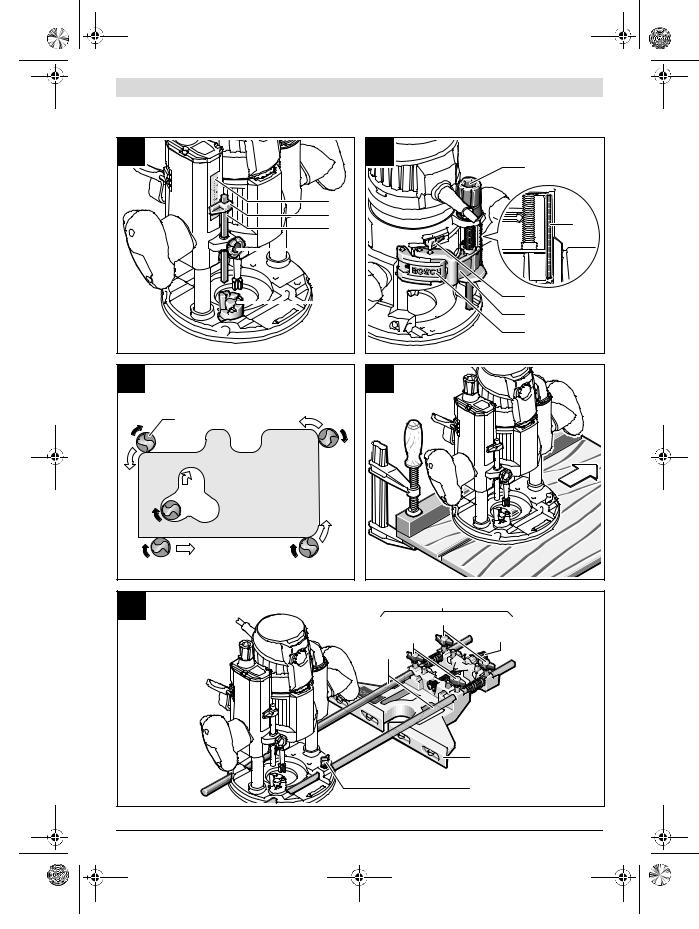
Adjusting the Depth-of-cut on the Plunge Base (see figure G)
For coarse adjustment of the depth-of-cut, proceed as follows:
–Place the machine with the router bit mounted on the workpiece to be machined.
–Set the scale for fine adjustment 6 to “0”.
–Set the turret stop 12 to the lowest setting; the turret stop can be felt to engage.
–Loosen the knurled screw at depth stop 16, so that the depth stop 11 moves freely.
–Press the release lever for plunge action 7 down and slowly guide the router down until the router bit 18 touches the workpiece surface. Let go of release lever 7 again to lock this plunging depth.
–Push the depth stop 11 down until it faces against the turret stop 12. Set the slide with the index mark 10 to the “0” position on the scale for depth-of-cut adjustment 9.
–Set the depth stop 11 to the desired routing depth and tighten the knurled screw 16 for the depth stop. Take care not to misadjust the slide with the index mark 10.
–Press the release lever for plunge action 7 and guide the router to the uppermost position.
The set routing depth is only reached when depth stop 11 touches the turret stop 12 while plunging.
For deep cuts, it is recommended to carry out several cuts, each with little material removal. By using the turret stop 12, the cutting process can be divided into several steps. For this, adjust the desired depth-of-cut to the lowest step of the turret stop and select the higher steps first for the initial cuts. The clearance of the steps is approx. 3.2 mm.
After a trial cut, the depth-of-cut can be set exactly to the desired measure by turning the adjustment knob 5; turn in clockwise direction to increase the cutting depth and in anticlockwise direction to decrease the cutting depth. The scale 6 can be used for guidance. One full turn corresponds with a setting range of 1.5 mm; a graduation mark on the top edge of the scale 6 corresponds with a 0.1 mm change of the setting range. The maximum setting range is ± 16 mm.
Example: The desired depth-of-cut is to be 10.0 mm; the trial cut resulted in a cutting depth of 9.6 mm.
–Press the release lever for plunge action 7 and guide the router to the uppermost position.
–Turn adjustment knob 5 by 0.4 mm/4 graduation marks (difference from nominal to actual value) in clockwise direction.
–Check the selected depth-of-cut by carrying out another trial cut.
When fine-adjusting the routing depth, take care that the index mark 8 on the side of the plunge base points towards the centre imprinted line. This measure ensures that there is sufficient travel in both directions for readjustment of the plunge depth.
When the plunge base 2 is lowered to the maximal plunge depth, cutting deeper by means of the fine adjustment is not possible, as the maximum travel has been utilised.
Fine adjustment is also not possible when the depth stop 11 faces against the turret stop 12.
Adjusting the Depth-of-cut on the Non-plunge Base (see figure H)
For adjustment of the depth-of-cut, proceed as follows:
–Open the clamping lever for the non-plunge base 22.
–Coarse pre-adjustment of the routing depth is possible in 3 steps. For this, press clamping lever 25 and slide the routing motor 1 up or down in the non-plunge base 3, until it, with the clamping lever 25 released, is locked in one of the 3 notches 26. The notches each have a clearance of
12.7 mm (0.5 ").
2 610 041 862 | (17.10.16) |
|
|
Bosch Power Tools |
||||
|
|
|
|
|
|
|
|
|
|
|
|
|
|
|
|
|
|
|
|
|
|
|
|

OBJ_BUCH-1559-002.book Page 15 Monday, October 17, 2016 7:29 PM
–The adjustment knob for depth-of-cut fine adjustment 24 is used for fine adjustment of the routing depth; turn clockwise to increase the routing depth, and anticlockwise to decrease the routing depth. The travel on the scale of adjustment knob 24 is indicated in inch and millimeter. The maximum setting range is 41 mm. The scale for depth-of- cut adjustment 34 provides added orientation.
Example: The desired depth-of-cut is to be 10.0 mm; the trial cut resulted in a cutting depth of 9.5 mm.
–Set the scale of the adjustment knob 24 to “0” without changing the setting of the adjustment knob 24 itself. Then set the adjustment knob 24 to the value “0.5” by turning in clockwise direction.
–Check the selected depth-of-cut by carrying out another trial cut.
Working Advice
Before any work on the machine itself, pull the mains plug.
Protect router bits against shock and impact.
Direction of Feed and Routing Process (see figure I)
The routing process must always be carried out against the rotation direction of the router bit 18 (up-cutting motion). When routing in the direction with the rotation of the router (down-cutting), the machine can break loose, eliminating control by the user.
For routing with the plunge base 2, proceed as follows:
–Adjust the required depth-of-cut; see Section “Adjusting the Depth-of-cut”.
–Place the machine with the router bit mounted on the workpiece to be machined and switch the power tool on.
–Press the release lever for plunge action 7 down and slowly guide the router down until the set depth-of-cut is reached. Let go of release lever 7 again to lock this plunging depth.
–Carry out the routing process applying uniform feed.
–After finishing the routing process, guide the router up to the uppermost position.
–Switch the power tool off.
For routing with the non-plunge base 3, proceed as follows:
–Note: Take into consideration that for routing work with the non-plunge base 3, the router bit 18 always protrudes out of the base plate 13. Do not damage the template or the workpiece.
–Adjust the required depth-of-cut; see Section “Adjusting the Depth-of-cut”.
–Switch the machine on and guide it to the location subject to routing.
–Carry out the routing process applying uniform feed.
–Switch the power tool off. Do not place the power tool down until the router bit has come to a standstill.
Routing with Auxiliary Guide (see figure J)
For working large workpieces, e. g., when routing grooves, a board or straight edge can be securely fastened to the workpiece as an auxiliary guide. The multifunction router can be guided alongside the path of this auxiliary guide. When using the plunge base 2, guide the guide plate (flattened side) of the multifunction router alongside the auxiliary guide.
English | 15
Shaping or Molding Applications
For shaping or molding applications without the use of a parallel guide, the router bit must be equipped with a pilot or a ball bearing.
–Guide the switched on power tool from the side toward the workpiece until the pilot or the ball bearing of the router bit faces against the workpiece edge to be machined.
–Guide the power tool alongside the workpiece edge with both hands, paying attention that the router is positioned rectangular. Too much pressure can damage the edge of the workpiece.
Routing with Parallel Guide (see figure K)
Slide the parallel guide 35 with the guide rods 36 into the base plate 13 and tighten as required with the wing bolts 41. Additionally, the parallel guide can be adjusted lengthwise with the wing bolts 37 and 38.
Fine adjustment of the length is possible with the fine-adjust- ment knob 39 after loosening both wing bolts 37. One revolution corresponds with a setting range of 2.0 mm. One graduation mark on the fine-adjustment knob 39 changes the setting range by 0.1 mm.
The effective contact surface of the parallel guide can be adjusted with the edge guide 40.
Guide the switched on power tool with uniform feed and lateral pressure on the parallel guide alongside the workpiece edge.
Routing with the Router Compass (see figure L)
The router compass/guide-rail adapter 42 can be used for circular routing jobs. Mount the router compass as shown in the figure.
Screw the centring screw 47 into the thread on the router compass. Insert the point of the centring screw into the centre of the circular arc to be routed, paying attention that point of the screw engages into the workpiece surface.
Coarsely adjust the required radius by moving the router compass and tighten the wing bolts 44 and 45.
The length can be fine adjusted with the fine-adjustment knob 46 after loosening the wing bolt 45. One revolution corresponds with a setting range of 2.0 mm. One graduation mark on the fine-adjustment knob 46 changes the setting range by 0.1 mm.
Guide the switched on power tool over the workpiece with the right handle 4 and the router compass handle 43.
Routing with Guide Rail (see figure M)
Straight routing cuts can be carried out with help of the guide rail 49.
The base spacer 48 must be mounted in order to compensate the height difference.
Mount the router compass/guide-rail adapter 42 as shown in the figure.
Fasten the guide rail 49 to the workpiece with suitable clamping devices, e. g. screw clamps. Place the machine with the guide-rail adapter 42 mounted onto the guide rail.
|
Bosch Power Tools |
2 610 041 862 | (17.10.16) |
|
||||
|
|
|
|
|
|
|
|
|
|
|
|
|
|
|
|
|
|
|
|
|
|
|
|

OBJ_BUCH-1559-002.book Page 16 Monday, October 17, 2016 7:29 PM
16 | English
Routing with Guide Bushing (see figures N–Q)
The guide bushing 53 enables template and pattern routing on workpieces.
In order to use the guide bushing 53, the guide bushing adapter 50 must be inserted into the guide plate 14 first.
Place the guide bushing adapter 50 from above onto the guide plate 14 and tighten it firmly with the 2 fastening screws 51. Pay attention that the release lever for the guide bushing adapter 52 is freely movable.
Choose a suitable guide bushing, depending on the thickness of the template or the pattern. Because of the projecting height of the guide bushing, the template must have a minimum thickness of 8 mm.
Actuate the release lever 52 and insert the guide bushing 53 from below into the guide bushing adapter 50. Ensure that the encoding keys clearly engage in the grooves of the guide bushing.
Check the clearance from router bit centre and guide bushing edge, see section “Centring the Base Plate”.
Select a router bit with a diameter smaller than the interior diameter of the guide bushing.
For routing with the guide bushing 53 proceed as follows:
–Note: Take into consideration that for routing work with the non-plunge base 3, the router bit 18 always protrudes out of the base plate 13. Do not damage the template or the workpiece.
–Guide the switched on power tool with the guide bushing toward the template.
–When using the plunge base 2: Press the release lever for plunge action 7 down and slowly guide the router down until the set depth-of-cut is reached. Let go of release lever 7 again to lock this plunging depth.
–Guide the switched on power tool with the protruding guide bushing alongside the template applying lateral pressure.
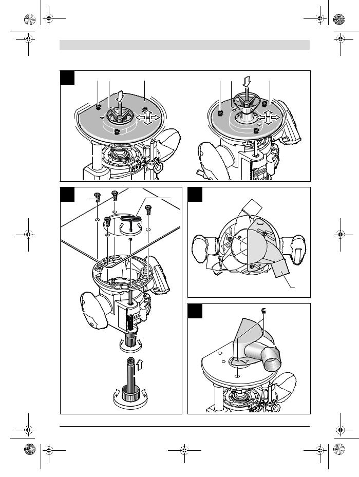
Centring the Base Plate (see figure R)
To ensure that the distance from router bit centre and guide bushing edge is uniform, the guide bushing and the guide plate can be adjusted to each other, if required.
–When using the plunge base 2: Press the release lever for plunge action 7 down and guide the router toward the base plate to the stop. Let go of release lever 7 again to lock this plunging depth.
–Loosen fastening screws 54 approx. 2 turns, so that guide plate 14 can move freely.
–Insert the centring pin 55 into the tool holder as shown in the figure. Hand-tighten the tightening nut so that the centring pin can still be moved freely.
–Align the centring pin 55 and the guide bushing 53 to each other by slightly moving the guide plate 14.
–Retighten the fastening screws 54 again.
–Remove the centring pin 55 from the tool holder.
–When using the plunge base 2: Press the release lever for plunge action 7 and guide the router back to the uppermost position.
Operation with Router Table (see figure S)
The non-plunge base 3 can be used with a suitable router table. To install the router, remove the guide plate 14 and fasten the non-plunge base 3 to the router table with the fastening screws 56.
For mounting of the non-plunge base, please observe the operating instructions of your router table. If necessary, matching holes must be drilled into the router table in order to mount the non-plunge base.
For fine adjustment of the depth-of-cut, it is best to use the extension 58 or the specialty Allen key 57.
Routing with Extraction Hood (see figures T– U)
For routing edges, the extraction hood 59 can additionally be used.
–Fasten the extraction hood 59 with the 2 fastening screws 60 to the base plate 13. The extraction hood 59 can be fastened in 3 different positions, as shown in the figure.
–Remove the extraction hood again for routing smooth plane surfaces.
Maintenance and Service
Maintenance and Cleaning
Before any work on the machine itself, pull the mains plug.
For safe and proper working, always keep the machine and ventilation slots clean.
In extreme conditions, always use dust extraction as far as possible. Blow out ventilation slots frequently and install a portable residual current device (PRCD).
When working metals, conductive dust can settle in the interior of the power tool. The total insulation of the power tool can be impaired.
If the replacement of the supply cord is necessary, this has to be done by Bosch or an authorized Bosch service agent in order to avoid a safety hazard.
After-sales Service and Application Service
Our after-sales service responds to your questions concerning maintenance and repair of your product as well as spare parts. Exploded views and information on spare parts can also be found under:
www.bosch-pt.com
Bosch’s application service team will gladly answer questions concerning our products and their accessories.
In all correspondence and spare parts orders, please always include the 10-digit article number given on the nameplate of the product.
2 610 041 862 | (17.10.16) |
|
|
Bosch Power Tools |
||||
|
|
|
|
|
|
|
|
|
|
|
|
|
|
|
|
|
|
|
|
|
|
|
|

OBJ_BUCH-1559-002.book Page 17 Monday, October 17, 2016 7:29 PM
English | 17
People’s Republic of China China Mainland
Bosch Power Tools (China) Co., Ltd. 567, Bin Kang Road
Bin Jiang District 310052 Hangzhou, P. R. China
Service Hotline: 4008268484 Fax: (0571) 87774502
E-Mail: contact.ptcn@cn.bosch.com www.bosch-pt.com.cn
HK and Macau Special Administrative Regions
Robert Bosch Hong Kong Co. Ltd. 21st Floor, 625 King’s Road North Point, Hong Kong
Customer Service Hotline: +852 2101 0235 Fax: +852 2590 9762
E-Mail: info@hk.bosch.com www.bosch-pt.com.hk
Indonesia
PT Robert Bosch Palma Tower 10th Floor
Jl. RA Kartini II-S Kaveling 6 Sek II Pondok Pinang, Kebayoran Lama Jakarta Selatan 12310 Indonesia
Tel.: (0 21) 30 05 5800
Fax: (0 21) 30 05 58 01
E-Mail: boschpowertools@id.bosch.com www.bosch-pt.co.id
Philippines
Robert Bosch, Inc.
28th Floor Fort Legend Towers, 3rd Avenue corner 31st Street, Fort Bonifacio Global City, 1634 Taguig City, Philippines Tel.: (02) 8703871
Fax: (02) 8703870 matheus.contiero@ph.bosch.com www.bosch-pt.com.ph
Bosch Service Center: 9725-27 Kamagong Street San Antonio Village
Makati City, Philippines Tel.: (02) 8999091 Fax: (02) 8976432
E-Mail: rosalie.dagdagan@ph.bosch.com
Malaysia
Robert Bosch Sdn. Bhd. No. 8A, Jalan 13/6 G.P.O. Box 10818 46200 Petaling Jaya Selangor, Malaysia
Tel.: (03) 79663194
Fax: (03) 79583838
E-Mail: cheehoe.on@my.bosch.com Toll-Free: 1800 880188 www.bosch-pt.com.my
Thailand
Robert Bosch Ltd. Liberty Square Building No. 287, 11 Floor Silom Road, Bangrak Bangkok 10500
Tel.: 02 6393111
Fax: 02 2384783
Robert Bosch Ltd., P. O. Box 2054 Bangkok 10501, Thailand www.bosch.co.th
Bosch Service – Training Centre
La Salle Tower Ground Floor Unit No.2
10/11 La Salle Moo 16
Srinakharin Road
Bangkaew, Bang Plee
Samutprakarn 10540
Thailand
Tel.: 02 7587555
Fax: 02 7587525
Singapore
Powerwell Service Centre Ptd Ltd
65 Ubi Crescent, #06-03 Hola Centre Singapore 408559
Tel.: 6746 9770/71 Fax: 6746 9760
E-Mail: powerwellsc@gmail.com Toll-Free: 1800 3338333 www.bosch-pt.com.sg
Vietnam
Robert Bosch Vietnam Co. Ltd 13th Floor , 194 Golden Building 473 Dien Bien Phu Street
Ward 25, Binh Thanh District 84 Ho Chi Minh City
Vietnam
Tel.: (08) 6258 3690
Fax: (08) 6258 3692 Hotline: (08) 6250 8555
E-Mail: tuvankhachhang-pt@vn.bosch.com www.bosch-pt.com.vn www.baohanhbosch-pt.com.vn
|
Bosch Power Tools |
2 610 041 862 | (17.10.16) |
|
||||
|
|
|
|
|
|
|
|
|
|
|
|
|
|
|
|
|
|
|
|
|
|
|
|

OBJ_BUCH-1559-002.book Page 18 Monday, October 17, 2016 7:29 PM
18 |
Australia, New Zealand and Pacific Islands
Robert Bosch Australia Pty. Ltd. Power Tools
Locked Bag 66
Clayton South VIC 3169
Customer Contact Center Inside Australia:
Phone: (01300) 307044 Fax: (01300) 307045 Inside New Zealand: Phone: (0800) 543353 Fax: (0800) 428570 Outside AU and NZ: Phone: +61 3 95415555 www.bosch-pt.com.au www.bosch-pt.co.nz
Egypt
Unimar
20 Markaz kadmat
El tagmoa EL Aoul – New Cairo
Tel: +2 02 224 76091 - 95 / + 2 02 224 78072 - 73 Fax:+2 02 224 78075
E-Mail: adelzaki@unimaregypt.com
Ethiopia
Forever plc
Kebele 2,754, BP 4806, Addis Ababa , Ethiopia
Tel: +251 111 560 600, +251 111 560 600 E-Mail: foreverplc@ethionet.et
Nigeria
C. Woermann Ltd. P.O. Box 318
6, Badejo Kalesanwo Street Matori Industrial Estate Lagos, Nigeria
Tel: +234 17 736 498, +234 17 730 904 E-Mail: d.kornemann@woermann-nigeria.com
Republic of South Africa
Customer service
Hotline: (011) 6519600
Gauteng – BSC Service Centre
35 Roper Street, New Centre Johannesburg
Tel.: (011) 4939375
Fax: (011) 4930126 E-Mail: bsctools@icon.co.za
KZN – BSC Service Centre
Unit E, Almar Centre
143 Crompton Street Pinetown
Tel.: (031) 7012120
Fax: (031) 7012446
E-Mail: bsc.dur@za.bosch.com
Western Cape – BSC Service Centre
Democracy Way, Prosperity Park
Milnerton
Tel.: (021) 5512577
Fax: (021) 5513223
E-Mail: bsc@zsd.co.za
Bosch Headquarters
Midrand, Gauteng
Tel.: (011) 6519600
Fax: (011) 6519880
E-Mail: rbsa-hq.pts@za.bosch.com
Disposal
The machine, accessories and packaging should be sorted for environmental-friendly recycling.
Do not dispose of power tools into household waste!
Subject to change without notice.
 !
!
" "
发事故。
尘或气体。
中会使操作者失去对工具的控制。
险。
如果你身体接地会增加电击危险。
电动工具将增加电击危险。
部件。
2 610 041 862 | (17.10.16) |
|
|
Bosch Power Tools |
||||
|
|
|
|
|
|
|
|
|
|
|
|
|
|
|
|
|
|
|
|
|
|
|
|

OBJ_BUCH-1559-002.book Page 19 Monday, October 17, 2016 7:29 PM
接软线。
使用剩余电流动作保护器RCD RCD
| 19
于那些与其用途不符的操作可能会导致危险。
瞬间的疏忽会导致严重人身伤害。
诸如适当条件下使用防尘面具、防滑安全鞋、安全 帽、听力防护等装置能减少人身伤害。
/
性。
可能造成操作者触电。
可能会卷入运动部件中。
尘屑引起的危险。
更安全。
且必须进行修理。
必须从电源上拔掉插头和/
是危险的。
事故由维护不良的电动工具引发。
刃的刀具不易卡住而且容易控制。
便不会被铣刀割伤。
稳固。
工具。
|
Bosch Power Tools |
2 610 041 862 | (17.10.16) |
|
||||
|
|
|
|
|
|
|
|
|
|
|
|
|
|
|
|
|
|
|
|
|
|
|
|

OBJ_BUCH-1559-002.book Page 20 Monday, October 17, 2016 7:29 PM
20 |
|
|
|
25 |
|
|
|
|
|
|
|||||||||||
|
|
|
|
|
26 |
|
|
|
|
|
|
|||||||||
|
|
|
|
27 |
|
|
|
|
|
|
|
|
|
|
|
|
||||
|
|
|
|
|
|
|
|
|
|
|
|
|
|
|
|
|||||
|
|
|
|
28 |
24 |
|
|
|
|
|
|
|
|
|
||||||
|
|
|
|
/ |
|
|
|
|
|
|
|
|
||||||||
|
|
|
|
29 |
|
|
|
|
|
|
|
|
|
|
|
|
|
|
||
|
|
|
|
|
|
(2x) |
* |
|
|
|
|
|
|
|
||||||
|
|
|
30 |
* |
|
|
|
|
|
|
|
|
||||||||
|
|
31 |
Ø 35 * |
|
|
|
|
|
|
|
|
|||||||||
|
|
|
|
|
|
|
|
|
|
|
|
|
|
|||||||
|
|
|
32 |
* |
|
|
|
|
|
|
|
|
||||||||
|
|
|
33 |
* |
|
|
|
|
|
|
|
|||||||||
|
|
|
34 |
|
|
|
|
|
|
|
|
|||||||||
|
|
|
|
|
|
|
|
|
|
|||||||||||
|
|
35 |
* |
|
|
|
|
|
|
|
|
|
|
|
||||||
|
|
|
|
|
|
|
|
|
|
|
|
|
|
|||||||
|
|
36 |
(2x) |
* |
|
|
|
|
|
|
|
|
||||||||
|
|
|
|
|
|
|
|
|
|
|
|
|
|
|||||||
|
|
|
37 |
(2x) |
* |
|
|
|
|
|
|
|||||||||
|
|
|
38 |
(2x) |
* |
|
|
|
|
|
|
|||||||||
|
|
1 |
|
39 |
* |
|
|
|
|
|
|
|
|
|||||||
|
|
2 |
|
40 |
* |
|
|
|
|
|
|
|
|
|||||||
|
|
3 |
|
41 |
(2x) |
* |
|
|
|
|
|
|
|
|||||||
|
|
4 |
|
42 |
/ * |
|
|
|
|
|
|
|
|
|||||||
|
|
5 |
|
43 |
* |
|
|
|
|
|
|
|
|
|
|
|||||
|
|
6 |
|
44 |
(2x) |
* |
|
|
|
|
|
|
|
|||||||
|
|
7 |
|
45 |
(1x) |
* |
|
|
|
|
|
|
|
|||||||
|
|
8 |
|
46 |
* |
|
|
|
|
|
|
|
|
|||||||
|
|
9 |
|
47 |
* |
|
|
|
|
|
|
|
|
|||||||
|
|
10 |
|
48 |
" " * |
|
|
|
|
|
||||||||||
|
|
11 |
|
49 |
* |
|
|
|
|
|
|
|
|
|
|
|
|
|||
|
|
12 |
|
50 |
SDS- |
|
|
|
|
|
|
|
|
|
||||||
|
|
13 |
|
51 |
(2x) |
|
|
|
|
|
|
|
|
|||||||
|
|
14 |
|
52 |
|
|
|
|
|
|
|
|
|
|||||||
|
|
15 |
|
53 |
|
|
|
|
|
|
|
|
|
|
|
|
|
|||
|
|
16 |
|
54 |
|
|
|
|
|
|
|
|
|
|
|
|||||
|
|
17 |
|
55 |
|
|
|
|
|
|
|
|
|
|
|
|
|
|||
|
|
18 |
* |
56 |
* |
|
|
|
|
|
|
|
|
|
||||||
|
|
19 |
|
57 |
* |
|
|
|
|
|||||||||||
|
|
20 |
|
58 |
* |
|
|
|
|
|
||||||||||
|
|
21 |
|
59 |
* |
|
|
|
|
|
|
|
|
|
||||||
|
|
22 |
/ |
60 |
* |
|
|
|
|
|
|
|
|
|
|
|||||
|
|
23 |
- |
* |
|
|
||||||||||||||
|
|
|
|
|
|
|
|
|
||||||||||||
|
|
24 |
|
|
|
|
|
|
|
|||||||||||
|
|
|
|
|
|
|
|
|
|
|
|
|
|
|
|
|
||||
|
|
|
|
|
|
|
|
|
|
|
|
|
|
|
|
|
|
|||
|
|
|
|
|
|
|
GOF 1600 CE |
|
|
GMF 1600 CE |
|
|
||||||||
|
|
|
|
|
|
3 |
601 |
F24 |
0.. |
|
3 |
601 |
F24 |
0.. |
|
|
||||
|
|
|
|
|
|
|
|
|
|
|
|
|
|
|
|
|
|
|||
|
|
|
|
|
|
|
|
1600 |
|
|
|
1600 |
|
|
||||||
|
|
|
|
|
|
|
|
|
|
|
|
|
||||||||
|
|
|
/ |
10000–25000 |
|
10000–25000 |
|
|
||||||||||||
|
|
|
|
|
|
|
|
|
|
|
|
|
|
|
|
|
|
|
|
|
|
|
|
|
|
|
|
|
|
|
|
|
|
|
|
|
|
|
|||
|
|
230 V |
|
|
|
|
|
|
|
|
|
|
|
|
||||||
|
|
|
|
|
|
|
|
|
|
|
|
|
|
|
|
|
|
|
|
|
|
|
2 610 041 862 | (17.10.16) |
|
|
|
|
|
|
|
|
|
Bosch Power Tools |
|
|
||||||
|
|
|
|
|
|
|
|
|
|
|
|
|
|
|
|
|
|
|
|
|
|
|
|
|
|
|
|
|
|
|
|
|
|
|
|
|
|
|
|
|
|
|
|
|
|
|
|
|
|
|
|
|
|
|
|
|
|
|
|
|
|
|
 Loading...